EP0031402A1 - Zusammengestellte Magnetköpfe zur Aufnahme/Wiedergabe und zum Tunnel-Löschen - Google Patents
Zusammengestellte Magnetköpfe zur Aufnahme/Wiedergabe und zum Tunnel-Löschen Download PDFInfo
- Publication number
- EP0031402A1 EP0031402A1 EP80105791A EP80105791A EP0031402A1 EP 0031402 A1 EP0031402 A1 EP 0031402A1 EP 80105791 A EP80105791 A EP 80105791A EP 80105791 A EP80105791 A EP 80105791A EP 0031402 A1 EP0031402 A1 EP 0031402A1
- Authority
- EP
- European Patent Office
- Prior art keywords
- erase
- core
- data transfer
- head assembly
- core portion
- Prior art date
- Legal status (The legal status is an assumption and is not a legal conclusion. Google has not performed a legal analysis and makes no representation as to the accuracy of the status listed.)
- Granted
Links
- 230000000712 assembly Effects 0.000 title description 2
- 238000000429 assembly Methods 0.000 title description 2
- 230000004907 flux Effects 0.000 claims abstract description 29
- 230000002463 transducing effect Effects 0.000 claims description 7
- 239000000463 material Substances 0.000 claims description 6
- 239000000696 magnetic material Substances 0.000 claims description 3
- 125000006850 spacer group Chemical group 0.000 description 6
- 239000000919 ceramic Substances 0.000 description 5
- 230000008878 coupling Effects 0.000 description 4
- 238000010168 coupling process Methods 0.000 description 4
- 238000005859 coupling reaction Methods 0.000 description 4
- 230000007704 transition Effects 0.000 description 4
- 238000004804 winding Methods 0.000 description 4
- 230000009471 action Effects 0.000 description 3
- 230000000694 effects Effects 0.000 description 3
- 239000000945 filler Substances 0.000 description 3
- 229910010293 ceramic material Inorganic materials 0.000 description 2
- 238000010276 construction Methods 0.000 description 2
- 230000004075 alteration Effects 0.000 description 1
- XBYNNYGGLWJASC-UHFFFAOYSA-N barium titanium Chemical compound [Ti].[Ba] XBYNNYGGLWJASC-UHFFFAOYSA-N 0.000 description 1
- 230000003993 interaction Effects 0.000 description 1
- 239000012762 magnetic filler Substances 0.000 description 1
- 239000006060 molten glass Substances 0.000 description 1
- 238000009966 trimming Methods 0.000 description 1
Images

Classifications
-
- G—PHYSICS
- G11—INFORMATION STORAGE
- G11B—INFORMATION STORAGE BASED ON RELATIVE MOVEMENT BETWEEN RECORD CARRIER AND TRANSDUCER
- G11B5/00—Recording by magnetisation or demagnetisation of a record carrier; Reproducing by magnetic means; Record carriers therefor
- G11B5/127—Structure or manufacture of heads, e.g. inductive
- G11B5/265—Structure or manufacture of a head with more than one gap for erasing, recording or reproducing on the same track
-
- G—PHYSICS
- G11—INFORMATION STORAGE
- G11B—INFORMATION STORAGE BASED ON RELATIVE MOVEMENT BETWEEN RECORD CARRIER AND TRANSDUCER
- G11B5/00—Recording by magnetisation or demagnetisation of a record carrier; Reproducing by magnetic means; Record carriers therefor
- G11B5/127—Structure or manufacture of heads, e.g. inductive
Definitions
- the invention relates to read/write and tunnel erase magnetic head assemblies.
- the magnetic head assembly disclosed in this patent includes a central read/write core having a read/write winding on one of the legs of the core and a pair of erase cores on the two sides of the read/write core. Erase gaps are provided in the two erase cores and are positioned quite close to a read/write gap in the read/write core longitudinally of the active face of the transducer on which the magnetic medium used in connection with the transducer travels so that the erase cores and the read/write core overlap to some extent.
- a single erase winding is disposed about the two erase cores and magnetically links the erase cores.
- Such a magnetic head functions very well under most circumstances; however, since portions of the erase cores and erase magnetic circuits overlap and run parallel to a portion of the read/write core and the read/write magnetic circuit, the DC induced flux in the erase cores causes a bias on the read/write magnetic circuit.
- the lengths of the erase gaps and the flux flowing through these gaps are transverse of the active transducer face and the direction of movement of the magnetic medium across the active face, and the erase gap lengths are thus of the same dimension as the widths of the edge magnetic track portions to be erased on the magnetic medium. Therefore, if the portions of a magnetic track to be erased have substantial width, the lengths of the erase gaps have this same substantial dimension; and very considerable power is needed in order to provide an effective erase flux in these erase gaps.
- the present invention provides a magnetic head assembly for combined transducing and tunnel erasing and including a transducing magnetic circuit and an erasing magnetic circuit characterized in that the erasing magnetic circuit has two erase gaps in series therein physically straddling the transducing gap, the two magnetic circuits sharing a common segment in this region in which the natural flux flows are substantially mutually perpendicular.
- an improved read/write and tunnel erase magnetic head assembly having a single erase core in which two opposite tunnel erase gaps are disposed carrying erase flux transversely to write flux through a portion of the write core for minimizing the coupling between the erase core and write core but with the arrangement being such that the erase gaps can be very short (in the direction of flux flow) while yet being effective to erase substantial side or marginal widths of a track written by the write gap of the magnetic head.
- a magnetic head assembly of the invention includes a central read/write core which is closed except for a read/write gap therein on the active face of the head assembly, a single erase core having portions disposed on opposite faces of a leg of the read/write core, two side portions of the erase core with the first named portions of the erase core forming erase gaps that extend substantially in the same direction as the read/write gap, with another erase core portion supporting the erase coil and extending between the pair of side core portions just mentioned.
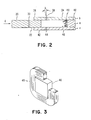
- the read/write core A comprises core portions 20 and 22 which are upstanding in the disposition of the head assembly shown in FIGs. 1, 4, 5 and 6 and are in a central layer a of the head assembly (see FIG. 2).
- the core portion 20 comprises an upper leg 20a and a tapered lower leg 20b, and the core A also includes a side bar 24 bridging and in contact with the core portions 20 and 22.
- the edge surfaces of the core portions 20 and 22 which are on the bottom in the disposition of the head assembly as it is shown in FIGs. 1, 4, 5 and 6 form a part of the elongate active face 26 of the head assembly, the core portions 20 and 22 extending away from and normally to face 26.
- Elongate face 26 (and also layer a) extend in direction X, and, in use, face 26 is in contact or near contact with a magnetic medium such as a magnetic disk 28 rotating in direction W and thus, effectively, passing longitudinally along the face 26 in direction X.
- a magnetic medium such as a magnetic disk 28 rotating in direction W and thus, effectively, passing longitudinally along the face 26 in direction X.
- a read/write coil 32 is disposed on the leg 20a for sensing or producing a magnetic flux that flows in path F through the read/write core A and across the gap 30.
- the erase core B includes the core portions 34 and 36 in an outer layer b (see FIG. 2) which extends longitudinally of the head assembly in direction X.
- the core portion 34 has an upstanding leg 34a and a downwardly tapering leg 34b extending toward the core portion 36 and forming an erase gap 38 therewith on the active face 26 of the assembly.
- the gap 38 does not extend precisely transversely of the direction X but rather has a small angle k, which may be about 15 degrees, with respect to an exact transverse or perpendicular to direction X.
- the core portion 36 extends normally with respect to the face 26 and is in contact for its length with a face of the core portion 22.
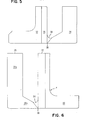
- the shapes of the core portions 34 and 36 in elevation may be seen in FIG. 5.
- the erase core B also includes core portions 40 and 42 which in elevation are substantially identical respectively with core portions 34 and 36, and FIG. 5 also therefore shows the shapes of the core portions 40 and 42.
- the core portions 40 and 42 are in an outer layer c (see FIG. 2) extending in direction X, and they provide an erase gap 44 between them on the active face 26.
- the gap 44 like the gap 38, also extends at the same small angle with respect to a perpendicular to the direction X, and the gap 44 like the gap 38, flares outwardly and reversely of direction X from the central layer a (see FIG. 2).
- the core portion 42 for its length lies in contact with a face of the core portion 22 opposite that with which core portion 36 makes contact.
- the erase core B also includes a core portion 46 bridging the core portions 34 and 40 and having its ends in contact or near contact with surfaces of the core portions 34 and 40.
- An erase coil 48 is wound about the core portion 46 and provides, when energized, magnetic flux extending in path G through the erase core 40. A part of the coil 48 lies between the core portions 34 and 40 as is clear from FIG. 1.
- All of the core portions previously mentioned including portions 20, 22, 24, 34, 36, 40, 42 and 46 are of magnetically permeable material so as to allow the magnetic flux extending in paths F and G to exist respectively in the core A and core B.
- the head assembly also includes ceramic spacers for filling out the various layers a, b and c and which have bottom surfaces on the face 26.
- the middle layer a is completed by the L-shaped spacer 50 of ceramic material which lies in face to face relationship with the core portion 22 (see FIG. 6).
- the outer layer b is completed by an L - shaped spacer 52 of ceramic material which is in face to face relationship with the core portion 36.
- the outer layer c is identical with the outer layer b except that the end faces of the core portions 40 and 42 are cut oppositely with respect to the end faces of the core portions 34 and 36 so that the gap 44 extends at an angle that flares outwardly opposite to the angle k shown in FIG. 2.
- All of the gaps 30, 38 and 44 are filled with a non-magnetic filler material.
- the fillers 54 and 56 for the gaps 30 and 38 are shown in FIGs. 6 and 5, and the filler for the gap 44 is similar. These fillers may be solidified molten glass, for example.
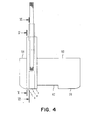
- the assembly is completed by outriggers 58 and 60 of non-magnetic material.
- the outrigger 58 is relatively thin and is fixed to the layer b, while the outrigger 60 is relatively wide and is fixed to the layer c.
- the outriggers 58 and 60 complete the active face 26, and the outrigger 60 is provided with a groove 62 opening into face 26 and is approximately centrally located with respect to the overall head extending in the longitudinal direction X.
- All of the non-magnetic parts, including the parts 52, 50, 58 and 60 may be made of a barium titanium ceramic, for example, as suggested in said U.S. patent 4,110,804.
- the coil 32 is electrically energized with an alternating current and produces an alternating magnetic flux in path F extending from core portion 20, through side bar 24, core portion 22 and gap 30 back to core portion 20.
- the gap 30 extends ' exactly transversely to direction X, and this has the effect of writing data magnetically with transitions in the same direction as that of gap 30 on the surface of the disk 28 that is in moving contact or near contact with the active face 26.
- a steady state direct current is supplied to the erase coil 48, and this produces a steady state magnetic flux that flows in path G through core portion 34, gap 38, core portion 36, core portion 22, core portion 42, gap 44 and core portion 40 and back to core portion 46. It is thus clear that all of the core portions in the erase core B are in series, and the single erase coil 48 is responsible for providing the magnetic flux in this series magnetic circuit.
- the same flux that flows through the erase gap 38 also flows through the erase gap 44, and the direction of flux flow through both gaps is longitudinally of the head assembly and elongate face 26 (in direction X or exactly opposite to direction X).
- the flux turns for 90 0 in core portions 36 and 42 to enter and leave core portion 22 and in passing through core portion 22 does so in a direction at 90 0 to path F.
- the magnetic flux passing across the gaps 38 and 44 thus has the effect of the trimming the boundaries or marginal edge portions of the data track previously written by the gap 30 as the disk 28 rotates in direction W so that the resultant track is of a predetermined restricted width.
- the flux across the gaps 38 and 44 can also be used to trim a previously written track on disk 28.
- the erase gaps 38 and 44 be close to the gap 30 in the direction X (for efficiency in formatting the magnetic track), and this has been accomplished by mounting the core portions 36 and 42 in contact with the core portion 22.
- the core portions 36 and 42 for their complete lengths are in contact with the core portion 22 on opposite faces of the latter as shown. Any undue magnetic interaction and coupling between the erase core B and read/write A is however, avoided, since the flux that passes through the gap 38 and through the core portion 36 then passes through the core portion 22 to the core portion 42 in a direction at 90 degrees with respect to the read/write flux in path F passing longitudinal of core portion 22.
- the erase gaps 38 and 44 extend essentially transversely with respect to the longitudinal direction X of the head assembly and in which the magnetic medium 28 moves on the elongate active face 26, these gaps may be relatively short in length (in the direction in which flux flows through the gaps, in direction X) while yet being effective to erase relatively wide widths on the edges of a previously recorded magnetic track on disk 28.
- the erase gaps 38 and 44 may have lengths (in the direction X), for example, from .0026 mm to .0043 mm and may have widths (perpendicular to direction X) of .165 mm.
- the erase gaps 38 and 44 which are relatively short in length (in direction X) and thus require a minimum amount of power nevertheless can erase a substantial width, such as .165 mm.
- the erase flux passes through the core portion 22 of the core A transversely thereto and transverse to the direction in which the flux in core A travels through the core portion 22 for reducing magnetic coupling as above mentioned, and this is accomplished essentially by turning the flux through 90 degrees from and to the erase gaps 38 and 44 in the erase core portions 36 and 42 for this purpose.
- the read/write gap 30 may for example have a length (in the direction X) from .00152 mm to .00342 mm, and its width (transverse to direction X) may be .33 mm. The read/write gap thus has a shorter length (in direction X) for better recording while having a considerably wider width (transverse to direction X) .
- the erase gaps 38 and 44 are preferably slanted with respect to a transverse or perpendicular to the direction X particularly for a reading action by the head assembly.
- the slant is shown by the angle k (FIG. 2), and the angle k can well vary from 0 degrees to 20 degrees.
- the gaps 38 and 44 are preferably slanted with respect to a transverse to the direction X so that the erase core B does not pick up signal from a previously written track that is being read by the core A, assuming that the track shifts slightly transversely of the direction X (at some time before the reading action).
- the gaps 38 and 44 extend essentially transversely with respect to the direction X so that the gaps 38 may be short in length (in direction X) and so that a minimum of power is required to provide the necessary erase flux across the gaps 38 and 44, using the coil 48.
- gaps 30, 38 and 44 may be made to the magnetic head structure above described and depicted in the attached drawings, all within the scope of the invention.
- the core portion 46 could be made round instead of square; and, with this alteration, the coil 48 in elevation would be round to correspond with the round core portion.
Landscapes
- Engineering & Computer Science (AREA)
- Manufacturing & Machinery (AREA)
- Magnetic Heads (AREA)
Applications Claiming Priority (2)
| Application Number | Priority Date | Filing Date | Title |
|---|---|---|---|
| US06/101,027 US4276574A (en) | 1979-12-06 | 1979-12-06 | Read/write and tunnel erase magnetic head assembly |
| US101027 | 1979-12-06 |
Publications (2)
| Publication Number | Publication Date |
|---|---|
| EP0031402A1 true EP0031402A1 (de) | 1981-07-08 |
| EP0031402B1 EP0031402B1 (de) | 1983-07-27 |
Family
ID=22282758
Family Applications (1)
| Application Number | Title | Priority Date | Filing Date |
|---|---|---|---|
| EP80105791A Expired EP0031402B1 (de) | 1979-12-06 | 1980-09-25 | Zusammengestellte Magnetköpfe zur Aufnahme/Wiedergabe und zum Tunnel-Löschen |
Country Status (3)
| Country | Link |
|---|---|
| US (1) | US4276574A (de) |
| EP (1) | EP0031402B1 (de) |
| DE (1) | DE3064427D1 (de) |
Cited By (2)
| Publication number | Priority date | Publication date | Assignee | Title |
|---|---|---|---|---|
| EP0106533A3 (de) * | 1982-09-13 | 1984-08-08 | Applied Magnetics Magnetic Head Division Corporation | Magnetkopfaufbau für eine flexible Platte |
| EP0193044A1 (de) * | 1985-02-27 | 1986-09-03 | Mitsubishi Denki Kabushiki Kaisha | Magnetkopf und Verfahren zu seiner Herstellung |
Families Citing this family (7)
| Publication number | Priority date | Publication date | Assignee | Title |
|---|---|---|---|---|
| US4514776A (en) * | 1981-05-08 | 1985-04-30 | Alps Electric Co., Ltd. | Magnetic head and method of manufacturing the same |
| JPS5860423A (ja) * | 1981-10-07 | 1983-04-09 | Hitachi Metals Ltd | 磁気ヘツド装置 |
| JPS595415A (ja) * | 1982-07-01 | 1984-01-12 | Alps Electric Co Ltd | 磁気ヘツド |
| US4541026A (en) * | 1982-07-20 | 1985-09-10 | Vertimag Systems Corporation | Hybrid read-write head for perpendicular recording media |
| JPS6061910A (ja) * | 1983-09-16 | 1985-04-09 | Mitsubishi Electric Corp | 磁気ヘツド組立体 |
| DE3524424A1 (de) * | 1984-07-10 | 1986-01-16 | Hitachi Maxell, Ltd., Ibaraki, Osaka | Magnetkopf |
| GB2242774B (en) * | 1990-02-16 | 1994-09-21 | Mitsubishi Electric Corp | Magnetic head |
Citations (9)
| Publication number | Priority date | Publication date | Assignee | Title |
|---|---|---|---|---|
| US2946859A (en) * | 1955-09-14 | 1960-07-26 | Loewe Siegmund | Magnetic recording heads |
| US3341667A (en) * | 1962-03-19 | 1967-09-12 | Ibm | Magnetic transducer with single piece core |
| US3485958A (en) * | 1966-09-15 | 1969-12-23 | Philips Corp | Composite magnetic recording and/or play-back head with two side erasing heads having electrically conductive strips |
| US3562443A (en) * | 1966-09-15 | 1971-02-09 | Philips Corp | Composite recording/playback head with two trim erase heads oriented at an angle to the record/playback head |
| US3576954A (en) * | 1968-09-16 | 1971-05-04 | Clevite Corp | Method of low power bias, low distortion magnetic recording |
| US3810244A (en) * | 1970-09-14 | 1974-05-07 | Canon Kk | Cross type magnetic head |
| US3846840A (en) * | 1973-08-10 | 1974-11-05 | Ibm | Read/write and longitudinal edge erase head assembly having multiple similarly shaped layers |
| US3882544A (en) * | 1973-12-14 | 1975-05-06 | Xerox Corp | Combined wide-erase and read-write magnetic head |
| US4110804A (en) * | 1977-07-21 | 1978-08-29 | International Business Machines Corporation | Read/write and tunnel erase magnetic head assembly |
Family Cites Families (2)
| Publication number | Priority date | Publication date | Assignee | Title |
|---|---|---|---|---|
| JPS4838826U (de) * | 1971-09-10 | 1973-05-14 | ||
| US3964103A (en) * | 1975-05-19 | 1976-06-15 | Shugart Associates, Inc. | Magnetic transducer with trim erase and housing therefor |
-
1979
- 1979-12-06 US US06/101,027 patent/US4276574A/en not_active Expired - Lifetime
-
1980
- 1980-09-25 DE DE8080105791T patent/DE3064427D1/de not_active Expired
- 1980-09-25 EP EP80105791A patent/EP0031402B1/de not_active Expired
Patent Citations (9)
| Publication number | Priority date | Publication date | Assignee | Title |
|---|---|---|---|---|
| US2946859A (en) * | 1955-09-14 | 1960-07-26 | Loewe Siegmund | Magnetic recording heads |
| US3341667A (en) * | 1962-03-19 | 1967-09-12 | Ibm | Magnetic transducer with single piece core |
| US3485958A (en) * | 1966-09-15 | 1969-12-23 | Philips Corp | Composite magnetic recording and/or play-back head with two side erasing heads having electrically conductive strips |
| US3562443A (en) * | 1966-09-15 | 1971-02-09 | Philips Corp | Composite recording/playback head with two trim erase heads oriented at an angle to the record/playback head |
| US3576954A (en) * | 1968-09-16 | 1971-05-04 | Clevite Corp | Method of low power bias, low distortion magnetic recording |
| US3810244A (en) * | 1970-09-14 | 1974-05-07 | Canon Kk | Cross type magnetic head |
| US3846840A (en) * | 1973-08-10 | 1974-11-05 | Ibm | Read/write and longitudinal edge erase head assembly having multiple similarly shaped layers |
| US3882544A (en) * | 1973-12-14 | 1975-05-06 | Xerox Corp | Combined wide-erase and read-write magnetic head |
| US4110804A (en) * | 1977-07-21 | 1978-08-29 | International Business Machines Corporation | Read/write and tunnel erase magnetic head assembly |
Non-Patent Citations (1)
| Title |
|---|
| PATENTS ABSTRACTS OF JAPAN, Vol. 4, No. 78, 6th June 1980, page 25P14 & JP-A-55 042 302 (MITSUBISHI) 25-03-1980. * |
Cited By (3)
| Publication number | Priority date | Publication date | Assignee | Title |
|---|---|---|---|---|
| EP0106533A3 (de) * | 1982-09-13 | 1984-08-08 | Applied Magnetics Magnetic Head Division Corporation | Magnetkopfaufbau für eine flexible Platte |
| EP0193044A1 (de) * | 1985-02-27 | 1986-09-03 | Mitsubishi Denki Kabushiki Kaisha | Magnetkopf und Verfahren zu seiner Herstellung |
| US4745676A (en) * | 1985-02-27 | 1988-05-24 | Mitsubishi Denki Kabushiki Kaisha | Method for manufacturing a magnet head |
Also Published As
| Publication number | Publication date |
|---|---|
| DE3064427D1 (en) | 1983-09-01 |
| EP0031402B1 (de) | 1983-07-27 |
| US4276574A (en) | 1981-06-30 |
Similar Documents
| Publication | Publication Date | Title |
|---|---|---|
| US3846840A (en) | Read/write and longitudinal edge erase head assembly having multiple similarly shaped layers | |
| EP0031402B1 (de) | Zusammengestellte Magnetköpfe zur Aufnahme/Wiedergabe und zum Tunnel-Löschen | |
| EP0111755A2 (de) | Magnetwandler mit Doppelelement | |
| ES8202446A1 (es) | Dispositivo de cabeza magnetica de registro y de lectura de datos | |
| JP7435466B2 (ja) | サーボライトヘッド、サーボパターン記録装置及び磁気テープの製造方法 | |
| GB1281636A (en) | Improvements in or relating to magnetic transducers | |
| US5734533A (en) | Dual gap magnetic head and method of making the same | |
| US3684841A (en) | Multi-channel magnetic transducer structure having full width erase head in non-magnetic housing | |
| US3956771A (en) | Magnetic transducer with side mounted ferrite core and method of making the same | |
| US4682254A (en) | Gimbal spring supported magnetic recording head | |
| JPH022207B2 (de) | ||
| US5251089A (en) | Magnetic head | |
| EP0174714A1 (de) | Aufbau eines magnetischen Wandlerkopfes und Verfahren zu dessen Anwendung | |
| JPS632988Y2 (de) | ||
| JPS61284810A (ja) | 垂直磁気ヘツド | |
| KR870006515A (ko) | 자기 테이프의 전진 및 후진방향 구동시의 정보기록 및 재생용 자기헤드 | |
| JPH05342526A (ja) | 磁気ヘッド | |
| JPS58171711A (ja) | 垂直磁化ヘツド | |
| JPS634244B2 (de) | ||
| JPS634243B2 (de) | ||
| JPS63263625A (ja) | 磁気ヘツドの製造方法 | |
| JPS61148617A (ja) | 磁気ヘツド | |
| JPS63144403A (ja) | 垂直磁気ヘツド | |
| JPS6325814A (ja) | デイジタル磁気ヘツド | |
| JPS6331853B2 (de) |
Legal Events
| Date | Code | Title | Description |
|---|---|---|---|
| PUAI | Public reference made under article 153(3) epc to a published international application that has entered the european phase |
Free format text: ORIGINAL CODE: 0009012 |
|
| AK | Designated contracting states |
Designated state(s): DE FR GB |
|
| 17P | Request for examination filed |
Effective date: 19810807 |
|
| GRAA | (expected) grant |
Free format text: ORIGINAL CODE: 0009210 |
|
| AK | Designated contracting states |
Designated state(s): DE FR GB |
|
| REF | Corresponds to: |
Ref document number: 3064427 Country of ref document: DE Date of ref document: 19830901 |
|
| ET | Fr: translation filed | ||
| PLBE | No opposition filed within time limit |
Free format text: ORIGINAL CODE: 0009261 |
|
| STAA | Information on the status of an ep patent application or granted ep patent |
Free format text: STATUS: NO OPPOSITION FILED WITHIN TIME LIMIT |
|
| 26N | No opposition filed | ||
| PGFP | Annual fee paid to national office [announced via postgrant information from national office to epo] |
Ref country code: GB Payment date: 19900803 Year of fee payment: 11 |
|
| PGFP | Annual fee paid to national office [announced via postgrant information from national office to epo] |
Ref country code: FR Payment date: 19900828 Year of fee payment: 11 |
|
| PGFP | Annual fee paid to national office [announced via postgrant information from national office to epo] |
Ref country code: DE Payment date: 19901004 Year of fee payment: 11 |
|
| PG25 | Lapsed in a contracting state [announced via postgrant information from national office to epo] |
Ref country code: GB Effective date: 19910925 |
|
| GBPC | Gb: european patent ceased through non-payment of renewal fee | ||
| PG25 | Lapsed in a contracting state [announced via postgrant information from national office to epo] |
Ref country code: FR Effective date: 19920529 |
|
| PG25 | Lapsed in a contracting state [announced via postgrant information from national office to epo] |
Ref country code: DE Effective date: 19920602 |
|
| REG | Reference to a national code |
Ref country code: FR Ref legal event code: ST |