EP0031272B1 - Verfahren und Vorrichtung zur Isotopentrennung durch Gasdiffusion - Google Patents
Verfahren und Vorrichtung zur Isotopentrennung durch Gasdiffusion Download PDFInfo
- Publication number
- EP0031272B1 EP0031272B1 EP80401754A EP80401754A EP0031272B1 EP 0031272 B1 EP0031272 B1 EP 0031272B1 EP 80401754 A EP80401754 A EP 80401754A EP 80401754 A EP80401754 A EP 80401754A EP 0031272 B1 EP0031272 B1 EP 0031272B1
- Authority
- EP
- European Patent Office
- Prior art keywords
- tubes
- conduits
- assembly
- microporous
- parallel
- Prior art date
- Legal status (The legal status is an assumption and is not a legal conclusion. Google has not performed a legal analysis and makes no representation as to the accuracy of the status listed.)
- Expired
Links
Images


Classifications
-
- B—PERFORMING OPERATIONS; TRANSPORTING
- B01—PHYSICAL OR CHEMICAL PROCESSES OR APPARATUS IN GENERAL
- B01D—SEPARATION
- B01D59/00—Separation of different isotopes of the same chemical element
- B01D59/10—Separation by diffusion
- B01D59/12—Separation by diffusion by diffusion through barriers
- B01D59/14—Construction of the barrier
Definitions
- the present invention relates to an isotopic separation process by gas diffusion by means of porous barriers.
- the devices currently known for ensuring the separation of isotopes by gas diffusion generally consist of an assembly of porous barriers having the form of microporous cylindrical tubes inside which the gaseous mixture to be separated is circulated in turbulent regime.
- the gas mixture By passing through these tubes, the gas mixture is separated into a fraction enriched in light isotope which diffuses through the wall of the tubes and in a fraction depleted in light isotope which is evacuated at the outlet of the tubes.
- an installation for the separation of isotopes by gas diffusion generally comprises a large number of elementary stages grouped in cascade, each elementary stage being constituted by an assembly of porous barriers.
- the stages are grouped so that the enriched fraction leaving one stage is sent to the next stage, while the depleted fraction leaving this same stage is sent to the stage previous.
- the enriched and depleted fractions leaving a stage must be compressed so that their pressure is reduced to the value chosen for the diffusion.
- the present invention specifically relates to an isotopic separation process by gas diffusion which makes it possible to significantly reduce the specific energy (power consumed per separation work unit in KWh / UTS) of an isotopic separation installation, thanks to the use of porous barriers having particular characteristics, and thanks to the flow regime established in these barriers.
- said gaseous mixture is put into circulation so as to establish a laminar enrégine flow of said mixture, the Reynolds number at the inlet of said tubes being less than 2000 and greater than 200.
- the invention also relates to an isotopic separation device for the implementation of this method.
- the average pore radius of said tubes is less than 200 A.
- the length of said microporous capillary tubes is greater than 25 cm.
- the capillary tubes have a thickness between 20 and 500 microns, a porosity between 10 and 60% and an air permeability between 10 - 10 - 7 and 100. 10- 7 mole / cm 2 x mn x cm Hg.
- said tubes are made of an inorganic material chosen from the group comprising alumina, magnesia, titanium oxide, silica, chromium oxide, mixed oxides of aluminum and magnesium and nickel, as well as certain metallic fluorides such as magnesium and nickel fluorides.
- said tubes are made of organic material, for example polytetrafluoroethylene.
- the microporous tubes used can have a circular section or even a polygonal section, for example a square or rectangular section.
- tube should be understood to mean a cylindrical surface generated by the displacement of a straight line or generator subject, on the one hand, to remain parallel to a fixed direction, and d on the other hand, to meet a closed and fixed plane curve, or director, whose plane cuts the given direction.
- a tube can have a section transverse circular, elliptical, square, polygonal, or any other shape, depending on whether the director is constituted by a circle, an ellipse, a square, a polygon or other.
- porous barriers having the form of capillary tubes of hydraulic diameter less than 0.5 and a length of at least 25 cm, and l establishment inside these tubes of a circulation of the gaseous mixture to be separated in laminar mode, makes it possible to obtain an improvement in the aerodynamic efficiency of the tubes, which also leads to a significant reduction in the pressure drop at l inside each tube.
- the specific energy of a stage of an isotopic separation installation corresponds to the ratio: in which W represents the energy consumed and ⁇ U the work of separation.
- the energy consumed W is the sum of the energy W ′ necessary to compress at the inlet pressure p e the diffused flow rate leaving the stage (n -1) at the pressure p av . and of the energy W "necessary to compress at the inlet pressure p e the lean flow leaving the stage (n + 1) at the pressure p s .
- the diffused flow Qe and the lean flow are equal to 2 , Qe being the input flow rate of each stage.
- Z is the aerodynamic efficiency given in laminar regime by the formula: in which R e is the Reynolds number at the entry of the microporous barrier, r h the hydraulic radius of the capillary tube, and L the length of the capillary tube and has a coefficient which depends on the section of the tube. In the case of capillary tubes of circular section, a is equal to 0.04511.
- the specific energy can thus be represented by the formula: In this formula, is in KW hour / UTS, ⁇ U is calculated with Qe expressed in kilograms of uranium per year. Also, with the method of the invention which leads to an increase in the value of the aerodynamic efficiency Z and to a decrease in the value ⁇ r, a lower specific energy is obtained.
- the assembly of microporous capillary tubes consists of microporous tubes arranged parallel to each other and subject at each of their ends to a plate, called assembly plate, said tubes being distributed in said assembly in rows parallel to a given direction, called first direction, also forming rows parallel to a second direction perpendicular to said first direction.
- the microporous capillary tubes have a circular section, and the tubes of each row parallel to the first direction are in tangential contact with each other.
- This embodiment of the assembly proves to be particularly advantageous since it leads to a very compact assembly comprising a large number of capillary tubes without creating disturbances in the flow of the gas having diffused through the wall of the tubes.
- the microporous capillary tubes are regularly spaced from one another in each of the rows parallel to the first or to the second direction.
- the distance d i between the planes defined by the axes of the tubes of two adjacent rows, parallel to the first direction is preferably greater than the distance d 2 between the axes of two adjacent tubes of a row parallel to the first direction.
- the distance d 2 is such that the value of (d 2 -d ex t) in which d ex t denotes the outside diameter of the tubes, is at most equal to 2 mm and the distance d i is such that the value of (di-dext) is between 0.5 and 3 mm.
- the assembly of microporous tubes consists of microporous tubes arranged parallel to each other and forming in said assembly a first series of conduits, called first conduits, delimited by the internal wall of said tubes, and this assembly comprises a plurality of longitudinal partitions integral with at least some of said tubes and distributed between said tubes so as to delimit with the external wall of the latter a second series of conduits, called second conduits, parallel to the first conduits.
- said tubes and said partitions are advantageously arranged together so that said second conduits all have the same cross section, and preferably a cross section such that the ratio of the cross section of said second conduits the cross section of said first conduits is between 1 and 20.
- the tubes of said assembly are mounted on two plates, said partitions extend from one to the other of said plates, and they have openings to ensure the evacuation of the separated circulating gas. in said second conduits.
- the tubes of said assembly are mounted on two plates, said partitions extend from one of said plates to close to the other of said plates so as to provide, in the vicinity of the other of said plates, openings for ensuring the evacuation of the separated gas circulating in said second conduits.
- the presence of longitudinal partitions which partially define in said assembly the conduits for receiving the gas separated by diffusion through the wall of the tubes makes it possible to improve the separation efficiency of the installation by creating a counter-current effect, that is to say by forcing the separated gas to circulate in the second conduits in the opposite direction to the gaseous mixture to be separated which circulates in the first conduits.
- This result can be obtained for example by providing in the longitudinal partitions openings arranged so as to allow only a discharge of the separated gas flowing in the second conduits in the immediate vicinity of the end of the tubes which corresponds to the entry of the gas mixture to to separate.
- the presence of the longitudinal partitions gives such an assembly good mechanical resistance due to the large transverse moment of inertia of the system and to the very tight network of partitions, which also makes it possible to obtain a low or negligible pressure drop in the second conduits where the gas separated by diffusion circulates.
- the partitions of said assembly are made of the same material as said tubes.
- the assembly comprising several tubes joined by longitudinal partitions can be manufactured directly in its final form from a paste of organic or inorganic microporous material, for example by extrusion of the paste through a die of geometry adapted to the shape of the assembly to be obtained, this extrusion being followed by a chemical and / or thermal treatment of the assembly thus obtained.
- the extrusion paste used can be constituted by any conventional extrusion material meeting the conditions required for the use of the assembly.
- the extrusion paste comprises grains of metal oxide such as alumina, magnesia, titanium oxide and silica which are coated for example with organic binders, preferably thixotropic such as the serine mixture terpineal.
- organic binders preferably thixotropic such as the serine mixture terpineal.
- Other binders such as water binders, in particular from the tragacanth family or else thermoplastic binders, can be used.
- the openings in the partitions can be made during the extrusion operation or after cooking of the assembly obtained, for example by mechanical machining or by cutting by laser radiation.
- these openings are made during the extrusion operation by stopping the injection of the dough by means of a comb at the points which correspond to the partitions, so as to interrupt these partitions over a length which represents for example 10% of the total length of the tubes, preferably at one of their ends.
- the assembly is constituted by a cellular module whose walls made of microporous material having an average radius of pores less than 200 A define rows of parallel channels having a square or rectangular cross section , said rows alternately constituting a first series of conduits, called first conduits, which have a hydraulic diameter of less than 0.5 cm and in which the gas mixture to be separated is circulated, and a second series of conduits, called second conduits, in which the gas separated by diffusion is collected through the wall of said first conduits.
- first conduits which have a hydraulic diameter of less than 0.5 cm and in which the gas mixture to be separated is circulated
- second conduits in which the gas separated by diffusion is collected through the wall of said first conduits.
- these second conduits are closed at each of their ends, openings being formed in each row of said second conduits so as to evacuate the gas separated by the side walls of the module.
- the isotopic separation device preferably comprises several assemblies of microporous capillary tubes.
- the device advantageously comprises a cylindrical enclosure in which are arranged one after the other a plurality of assemblies of microporous tubes which are parallel to the axis of the enclosure, said assemblies being each mounted between two plates known as diffuser plates and separated from one another so as to provide between two neighboring assemblies and at each end of the enclosure of the successive chambers which alternately constitute distribution chambers of the gaseous mixture to be separated in the microporous tubes opening into these last and collection chambers of the gas leaving the tubes opening into the latter, means for supplying said distribution chambers with gas mixture to be separated, means for extracting from said collection chambers the gas leaving the tubes of said assemblies and means for collecting the gas having diffused through the wall of tubes of each of said assemblies.
- all the microporous tubes have a circular section.
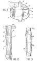
- an isotopic separation device comprising an enclosure 1 inside which are mounted vertically between two horizontal plates 3 and 5 known as diffuser plates, assemblies 7 of microporous capillary tubes having an internal diameter at most equal to 0.5 cm, advantageously less than 0.25 cm and preferably less than 0.12 cm.
- the diffuser plates are provided with openings for the fitting of each assembly and they are made for example of metal such as stainless steel, Monel, or a steel coated to resist corrosion, or also of plastic material. such as Teflon.
- the lower plate 5 delimits at the base of the enclosure 1 a chamber for introducing the gaseous mixture to be separated brought under high pressure by the pipe 9.
- This gaseous mixture then passes through the assemblies 7 of capillary tubes in which it is separated into an impoverished fraction which is evacuated under high pressure by following the path of the arrows F i via the pipe 11 and into an enriched fraction by diffusion through the wall of the capillary tubes which is evacuated, under low pressure, following the path of the arrows F 2 , through the pipe 13.
- the plates 3 and 5 are interconnected by a perforated vertical partition 15 which delimits with the internal wall of the enclosure 1 an annular passage for the evacuation of the gases at low pressure towards the pipeline 13.
- the upper plate 3 is surmounted by a dome 17 which delimits with the plate 3 a high pressure gas collecting chamber.
- an assembly 7 consists of a plurality of microporous capillary tubes 21 arranged parallel to each other and subject at each of their ends to a plate called an assembly plate of which only the upper plate 23 is shown in this figure.
- These assembly plates are provided with circular openings of diameter substantially equal to the outside diameter of the capillary tubes 21 and they are advantageously made of metal such as nickel or aluminum.
- the sealing at the level of the passages of the tubes 21 in the openings of the assembly plates 23 is achieved for example by means of a phosphated glass such as P 106.
- the microporous capillary tubes 21 of the assembly 7 consist of elementary capillary tubes such as 21a and 21b assembled end to end by means of cylindrical sleeves 25 made for example of aluminum or nickel, and having for example a thickness of about 0.2 mm.
- the seal between the sleeve 25 and the elementary tubes 21a a and 21b is produced by a deposit 27 of aluminum or alumina powder applied for example by spraying or by scooping.
- Sealing between the tubes 21a a and 21b can also be achieved by means of phosphate glasses resistant to uranium hexafluoride such as "P 106", or fluoride glasses or also by means of adhesives or emulsions with polytetrafluoroethylene base.
- P 106 uranium hexafluoride
- fluoride glasses or also by means of adhesives or emulsions with polytetrafluoroethylene base.
- the elementary tubes 21a a and 21b have a thickness of between 20 and 500 microns, a porosity of 10 to 60%, a permeability to air of between 10. 10- 7 and 100. 10- 7 mole / cm 2 per minute per centimeter of mercury.
- the capillary tubes 21 preferably have a length greater than 50 cm, and they generally comprise several elementary tubes such as 21 a assembled end to end.
- the tubes 21 of an assembly 7 are held radially by elastic clamping means 27 at the sleeves 25, these sleeves 25 thus being in contact with each other and ensuring moreover maintaining the tubes 21 at a given spacing which corresponds to the thickness of the sleeves 25.
- These elastic clamping means are constituted for example by strips of metal strip or of plastic material such as Teflon.
- the tubes are assembled in a hexagonal pattern.
- the tubes 21 can also be assembled in a hexagonal bundle and maintained at a desired spacing by means of a metallic or plastic canvas with square mesh of side substantially equal to the external diameter of the tubes by placing the tubes 21 in the locations of the metallic canvas which correspond to every second stitch.
- the assembly plate 23 is connected by means of a metal bellows 29 to a metallic annular piece 31 whose free edge is made integral with the edge of the opening of the plate 3, for example by means of a ring 33.
- the diffuser advantageously comprises a thousand assemblies each comprising three hundred microporous capillary tubes. These assemblies are arranged in a hexagonal pattern in the corresponding openings, of approximately 30 mm in diameter of the plates 3 and 5, the distance between the centers of the assemblies being approximately 37 mm.
- the thousand assemblies thus occupy a cross section of 4.74 m 2 , which corresponds to a circular section of 2.46 m in diameter.
- the inlet flow rate of a tube is 0.0106 g of UF 6 / sec.
- the total flow rate of the device comprising one thousand assemblies of three hundred tubes will be 3.18 kg of U F 6 / sec.
- the diameters of the pipes 9, 11, 13 are calculated so that the gas speed in each of these pipes is 2 m / sec.
- FIG 7 there is shown in perspective an assembly 7 of microporous capillary tubes corresponding to the first embodiment of the invention.
- the microporous capillary tubes 21 are mounted at their end on a plate 23 produced from unitary elements 23a welded together.
- the microporous tubes 21 are distributed in rows parallel to a first direction OX, the plane defined by the axes of the tubes of a row being at a distance d 1 , greater than the external diameter d ext of said tubes, of the plane defined by the axes of the tubes of an adjacent row.
- microporous tubes 21 are further distributed so as to also form rows of tubes parallel to a second direction OY perpendicular to the first direction OX.
- the tubes are spaced regularly from each other at a distance d 2 which represents the interval separating the axes of two adjacent tubes.
- the distance d i is greater than the distance d 2 , so as to define between the rows of tubes parallel to the first direction OX of the corridors which promote an appropriate flow of the gaseous mixture having diffused through the wall of the tubes 21, which makes it possible to obtain a very compact assembly while minimizing the pressure losses between the tubes for the gaseous mixture diffused through the wall of the tubes.
- the tubes 21 are mounted in leaktight manner at their ends on plates 23, only one of which is shown in the drawing, made for example of teflon.
- the plate 23 is formed from unitary elements 23a which have a profile such that two elements 23a can completely surround either a row of tubes parallel to the first direction OX, or a row of tubes parallel to the second direction OY, the elements 23a being welded together, for example by hot pressing, to form a plate 23 in which the ends of the tubes 21 are mounted in leaktight manner.
- the tubes 21 can be maintained at an appropriate spacing by spacers 25 distributed at different levels of the assembly 7, these spacers 25 can also be produced from elementary parts of the same type 25a as those which constitute the plates 23, without any 'However, it is necessary to tightly secure these parts together to obtain a sealed system.
- FIG. 9 another example of embodiment of the assembly 7 has been shown, which differs from the embodiment of FIG. 8 by the fact that the microporous tubes 21 of the rows parallel to the first direction OX are in tangential contact with the with each other.
- these tube assemblies are arranged in the device in such a way that the corridors formed between the rows of tubes parallel to the direction OX are substantially in the axis of the diffuse gas outlet pipe.
- the assembly 7 comprises microporous tubes 21 arranged parallel to one another and a plurality of longitudinal partitions 22 disposed between the tubes 21 and fixed on the latter.
- a first series of conduits 24 defined by the internal wall of the microporous tubes 21 and a second series of conduits 30 delimited by the external wall of the tubes 21 and by the partitions 22 are defined in the assembly.
- the tubes 21 are mounted at their upper end on the plate 23 and at their lower end on the plate 23 '.
- the partitions 22 extend longitudinally of the plate 23 up to the proximity of the plate 23 ', so as to provide in the immediate vicinity of the plate 23' openings making it possible to ensure the evacuation of the enriched gas which circulates in the second conduits 30 delimited between the tubes 21 by the partitions 22 and the outside of the wall of the tubes 21.
- the openings intended to ensure the evacuation of the gas flowing in can be arranged differently in the assembly 7.
- the partitions 22 can extend longitudinally from the plate 23 to the plate 23 ′ and be provided with openings distributed uniformly between said plates.
- the openings of the second conduits 30 are located in the immediate vicinity of the end plate 23 'of the assembly, which corresponds to the entry (arrow F i ) in the tubes 21 of the gas under high pressure in order to create a counter-current effect in the second conduits 30 by circulating the enriched gas (arrow F 2 ) in the opposite direction to the gas mixture which circulates in the microporous tubes 21.
- the assembly of the assembly 7 on the plates 3 and 5 of the enclosure 1 is carried out by means of the end plates 23 and 23 ′ produced for example in Teflon, and secured to the tubes 21 and the partitions 22.
- Sealing can also be achieved by casting a material resistant to corrosion of fluorinated products, for example by means of a phosphated glass such as P 106.
- the partitions 22 when the partitions 22 must be interrupted in the vicinity of an end plate in order to provide openings in the second conduits, the corresponding end plate is mounted on the tubes 21 without resting it on the partitions 22, and then only a seal is made between the tubes 21 and the end plate.
- the assembly 7 can be mounted on the plates 3 and 5 by means of a metal end-piece fixed to each end of the assembly and then crimped into the corresponding openings of the plates 3 and 5.
- Figure 12 there is shown a partial view in horizontal section of an assembly of circular section tubes in which the tubes are distributed in a rectangular pitch.
- the microporous tubes 21 are distributed in parallel rows, in two orthogonal directions OX and OY.
- the tubes 21 of the rows parallel to the direction OY are in tangential contact with each other, while the tubes 21 of the rows parallel to the direction OX are regularly spaced from each other in each row, two adjacent tubes of a row being joined by partitions 22 parallel to the direction OX.
- two hundred microporous tubes having an internal diameter of 1 mm and an external diameter of 1.5 mm can be assembled in this way with partitions with a length of 1.5 mm and a thickness of 0.3 mm.
- the assembly thus obtained has a section of 2.85 cm by 3 cm on a side and comprises rows of ten tubes in the direction OX and twenty tubes in the direction OY.
- the ratio of the cross section of the first conduits delimited inside the tubes 9 and the second conduits delimited by the partitions and the external wall of the tubes 9 is 3.48.
- Figure 13 there is shown a partial view in horizontal section of an assembly of circular section tubes in which the microporous tubes are distributed in a square pitch.
- the microporous tubes 21 are distributed in rows parallel to two orthogonal directions OX and OY; the tubes 21 of the rows parallel to the direction OY are regularly spaced from each other and partitions 22 parallel to the direction OY are provided between two adjacent tubes of each row; the tubes 21 of the rows parallel to the direction OX are regularly spaced from one another and partitions 22 parallel to the direction OX are provided in a row on two of the tubes parallel to the direction OX, so as to join two adjacent tubes of the same row.
- 169 microporous tubes having an internal diameter of 1 mm, an external diameter of 1.50 mm, were assembled in this way, with partitions of 0.75 mm in length and 0.3 mm in diameter. thickness.
- the ratio of the cross section of the second conduits to the cross section of the first conduits is 6.45.
- Such an assembly comprising 169 tubes has a square section of 2.85 cm on each side, each row of tubes parallel to the direction OX or to the direction OY being made up of thirteen tubes.
- Figure 14 there is shown a partial view in horizontal section of an assembly of circular section tubes in which the tubes are distributed in a rectangular pitch.
- the microporous tubes 21 are distributed in rows parallel to two orthogonal directions OX and OY, the tubes 21 of the rows parallel to the direction OY being in tangential contact with each other and the tubes 21 of the rows parallel to the direction OX being spaced regularly from each other.
- the partitions 22 are distributed obliquely between two successive rows of tubes parallel to OY, so as to join a tube of a row parallel to OX to a tube of the adjacent row parallel to OY.
- this assembly comprises partitions 22 'between adjacent tubes on the two rows of tubes parallel to OX situated at the periphery of the assembly.
- the ratio of the cross section of the second conduits 30 delimited between the tubes 21 by the partitions 22 to the cross section of the first conduits is 2.86.
- the microporous tubes are distributed in rows parallel to two orthogonal directions OX and OY; the tubes 21 of the rows parallel to the direction OY are in contact with one another by one of their edges and the tubes 21 of the rows parallel to the direction OX are regularly spaced from one another, two adjacent tubes being joined by a partition longitudinal parallel to the direction OX.
- FIGS. 12 to 15 Several assemblies such as those illustrated in FIGS. 12 to 15 can be mounted between the plates 3 and 5 of the device in FIG. 1, leaving an interval of the order of 5 mm between each assembly to allow evacuation to the outlet 13 of the diffused gas leaving each assembly.
- the assembly 7 is constituted by a cellular module whose walls made of microporous material define rows of channels designated alternately by the references 101 and 103.
- the channels of the rows 101 constitute a first series of conduits 105, called first conduits, which have a hydraulic diameter of less than 0.5 cm; the channels of the rows 103 constitute a second series of conduits 107, called second conduits.
- the channels have a square or rectangular section and that two adjacent channels have a common wall.
- the gas mixture to be separated is circulated (arrow F i ) and in the second series of conduits 107, the separated gas is collected by diffusion through the wall of the first conduits (arrow F 2 ).
- the second conduits 107 are closed at each of their ends and openings 109 on each row of channels 107 are created at the upper part of the module to ensure the evacuation of the gas separated at the side walls of the module.
- openings can be made in the following manner. After manufacturing the module, notches such as 111 are produced on the rows of channels 103, for example by machining using an appropriate tool, then the upper parts of the module which correspond to the rows 103 are closed, covering them with a waterproof material 113. Thus, it is possible to ensure the evacuation of the gas diffused by the side walls of the module, and to circulate the gas mixture to be separated in the conduits 105 by introducing it into the upper part of the module.
- This device comprises a cylindrical enclosure 1 of vertical axis in which are arranged vertically, one after the other, four assemblies of microporous capillary tubes 7a, 7b, 7c, 7d.
- Each of the microporous tube assemblies is mounted between two plates, called diffuser plates, such as 3a and 5a ... 3d and 5d.
- These assemblies are separated from each other so as to provide space between two neighboring assemblies such as 7a and 7b and at each of the ends of the enclosure of the successive chambers C l , C 2 , C 3 , C 4 , and C 5 .
- chambers C 2 , C 3 and C 4 are delimited by the diffuser plates of two neighboring assemblies, for example the chamber C 2 , by the plates 5a and 3b of the neighboring assemblies 7a and 7b and that they are in communication with the tubes of these two assemblies.
- end chambers Ci and C 5 are only in communication with the tubes of a single assembly such as 7a or 7d.
- the successive chambers Ci to C 5 constitute alternately chambers for distributing the gas mixture to be separated and chambers for collecting the gas mixture leaving the tubes of the assemblies.
- the chambers C 2 and C 4 constitute distribution chambers which make it possible respectively to distribute in the microporous tubes of two neighboring assemblies 7a, 7b and 7c, 7d the gaseous mixture to be separated; similarly, the chambers Ci, C 3 and C 5 constitute collection chambers, the chamber C 3 being intended to collect the gaseous mixture leaving the tubes of two neighboring assemblies 7b and 7c, and the chambers Ci and C 5 ensuring only the collection of the gas leaving the assemblies 7a and 7d respectively.
- the gas mixture to be separated by diffusion through microporous tubes of the various assemblies of the device is introduced by pipes 92, 94 into the chambers C 2 and C 4 ; this gas then passes by following the path of arrows F 1 in the microporous tubes of each of the assemblies of the device and it is collected in the collection chambers Ci, C 3 , Cs (arrow F 3 ) then evacuated from the device by extraction pipes 11 1 , 11 3 , 11 5 .
- the gas mixture By passing through the capillary tubes of the assemblies 7a to 7d, the gas mixture is separated by diffusion following the path of the arrows F 2 through the wall of the tubes in an enriched fraction which is collected by following the path of the arrows F 2 in an annular collection space 40 located at the periphery of the enclosure, then evacuated from this collection space by a pipe 13 located at the base of the enclosure.
- the assemblies such as 7a to 7d may include one or more bundles in which the microporous capillary tubes are tightly mounted directly on the diffuser plates 3a and 5a, 3b and 5b, etc. or in which the microporous tubes are subjected at each of their ends to beam plates by means of which they are mounted on the diffuser plates as has been described previously (FIGS. 5 and 6).
- a device of this type has been produced in which four assemblies have been put in place, each comprising 750,000 microporous capillary tubes of circular section having an internal diameter of 1 mm, an external diameter of 1.5 mm, 1.50 m long, 20% porosity, 40 air permeability. 10- 7 mole / cm 2 x mn x cm Hg and an average pore radius of 100 ⁇ . These assemblies are arranged in a cylindrical enclosure having an external diameter of 2.7 m and a total length of 9.50 m, the successive chambers having a height of 70 cm.
- the total flow rate of gas capable of being treated in a plant of this type is 99 kg of uranium hexafluoride per second, the flow rates of entry into each assembly being 24.75 kg of hexafluoride d uranium per second, this uranium hexafluoride being separated in each assembly into a depleted fraction of a flow rate of 12.375 kg / s per assembly and into an enriched fraction of a flow rate of 12.375 kg / s per assembly.
Landscapes
- Chemical & Material Sciences (AREA)
- Chemical Kinetics & Catalysis (AREA)
- Separation Using Semi-Permeable Membranes (AREA)
Claims (28)
Applications Claiming Priority (2)
| Application Number | Priority Date | Filing Date | Title |
|---|---|---|---|
| FR7930862A FR2471208A1 (fr) | 1979-12-17 | 1979-12-17 | Procede et dispositif pour la separation isotopique par diffusion gazeuse |
| FR7930862 | 1979-12-17 |
Publications (2)
| Publication Number | Publication Date |
|---|---|
| EP0031272A1 EP0031272A1 (de) | 1981-07-01 |
| EP0031272B1 true EP0031272B1 (de) | 1983-11-09 |
Family
ID=9232843
Family Applications (1)
| Application Number | Title | Priority Date | Filing Date |
|---|---|---|---|
| EP80401754A Expired EP0031272B1 (de) | 1979-12-17 | 1980-12-08 | Verfahren und Vorrichtung zur Isotopentrennung durch Gasdiffusion |
Country Status (8)
| Country | Link |
|---|---|
| US (1) | US4427424A (de) |
| EP (1) | EP0031272B1 (de) |
| JP (1) | JPS5697527A (de) |
| AU (1) | AU6541280A (de) |
| CA (1) | CA1151079A (de) |
| DE (1) | DE3065559D1 (de) |
| ES (1) | ES497797A0 (de) |
| FR (1) | FR2471208A1 (de) |
Families Citing this family (16)
| Publication number | Priority date | Publication date | Assignee | Title |
|---|---|---|---|---|
| US4482360A (en) * | 1982-05-29 | 1984-11-13 | Nippon Steel Corporation | Porous materials for concentration and separation of hydrogen or helium, and process therewith for the separation of the gas |
| US4671809A (en) * | 1984-06-05 | 1987-06-09 | Nippon Steel Corporation | Gas separation module |
| WO1989001819A1 (en) * | 1987-09-01 | 1989-03-09 | Alan Krasberg | Apparatus for and method of providing improved gas separation |
| GB8830107D0 (en) * | 1988-12-23 | 1989-02-22 | Boc Group Plc | Gas separation |
| DE3921390A1 (de) * | 1989-06-29 | 1991-01-17 | Merck Patent Gmbh | Verfahren und vorrichtung zur gewinnung von reinem sauerstoff |
| US5419820A (en) * | 1993-06-02 | 1995-05-30 | The United States Of America As Represented By The United States Department Of Energy | Process for producing enriched uranium having a 235 U content of at least 4 wt. % via combination of a gaseous diffusion process and an atomic vapor laser isotope separation process to eliminate uranium hexafluoride tails storage |
| DE4412756C2 (de) * | 1994-04-13 | 1996-06-20 | Gore W L & Ass Gmbh | Schlaucheinheit und Verfahren zur Herstellung derselben |
| US5468283A (en) * | 1994-07-21 | 1995-11-21 | Transfair Corporation | Hollow fiber membrane modules with transverse gas flow tailored for improved gas separation |
| US6461408B2 (en) | 1995-11-06 | 2002-10-08 | Robert E. Buxbaum | Hydrogen generator |
| WO1997017125A1 (en) * | 1995-11-06 | 1997-05-15 | Buxbaum Robert E | Apparatus and methods for gas extraction |
| US5931987A (en) * | 1996-11-06 | 1999-08-03 | Buxbaum; Robert E. | Apparatus and methods for gas extraction |
| US6098676A (en) * | 1998-02-10 | 2000-08-08 | Vital Signs Inc. | Aseptic liquid fillings |
| NL1008381C2 (nl) * | 1998-02-20 | 1999-08-24 | X Flow Bv | Filterinrichting. |
| US6126833A (en) * | 1999-02-22 | 2000-10-03 | Ceramem Corporation | Cross-flow filtration device with filtrate conduit network and method of making same |
| DK2327466T3 (da) * | 2009-11-12 | 2014-08-25 | Novomatic Ag | Luftrenser til fjernelse af luftforurening fra en luftstrøm |
| US9034083B2 (en) * | 2012-04-10 | 2015-05-19 | Vivonics, Inc. | Array of hollow fibers and a system and method of manufacturing same |
Citations (1)
| Publication number | Priority date | Publication date | Assignee | Title |
|---|---|---|---|---|
| FR2345204A1 (fr) * | 1976-03-23 | 1977-10-21 | Pinto De Novais Paiva Manuel | Procede de separation de substances de masses differentes, et appareil et installation pour sa mise en oeuvre |
Family Cites Families (1)
| Publication number | Priority date | Publication date | Assignee | Title |
|---|---|---|---|---|
| CH608385A5 (en) * | 1976-05-07 | 1979-01-15 | Commissariat Energie Atomique | Group of assembled tubes for diffusers |
-
1979
- 1979-12-17 FR FR7930862A patent/FR2471208A1/fr active Granted
-
1980
- 1980-12-02 US US06/212,138 patent/US4427424A/en not_active Expired - Lifetime
- 1980-12-08 DE DE8080401754T patent/DE3065559D1/de not_active Expired
- 1980-12-08 EP EP80401754A patent/EP0031272B1/de not_active Expired
- 1980-12-10 CA CA000366497A patent/CA1151079A/en not_active Expired
- 1980-12-16 ES ES497797A patent/ES497797A0/es active Granted
- 1980-12-16 AU AU65412/80A patent/AU6541280A/en not_active Abandoned
- 1980-12-17 JP JP17733180A patent/JPS5697527A/ja active Pending
Patent Citations (1)
| Publication number | Priority date | Publication date | Assignee | Title |
|---|---|---|---|---|
| FR2345204A1 (fr) * | 1976-03-23 | 1977-10-21 | Pinto De Novais Paiva Manuel | Procede de separation de substances de masses differentes, et appareil et installation pour sa mise en oeuvre |
Also Published As
| Publication number | Publication date |
|---|---|
| ES8207436A1 (es) | 1982-09-16 |
| JPS5697527A (en) | 1981-08-06 |
| ES497797A0 (es) | 1982-09-16 |
| EP0031272A1 (de) | 1981-07-01 |
| DE3065559D1 (en) | 1983-12-15 |
| CA1151079A (en) | 1983-08-02 |
| FR2471208B1 (de) | 1982-01-15 |
| FR2471208A1 (fr) | 1981-06-19 |
| AU6541280A (en) | 1981-06-25 |
| US4427424A (en) | 1984-01-24 |
Similar Documents
| Publication | Publication Date | Title |
|---|---|---|
| EP0031272B1 (de) | Verfahren und Vorrichtung zur Isotopentrennung durch Gasdiffusion | |
| FR2500610A1 (fr) | Echangeur de chaleur a plaques perforees | |
| EP1212755B1 (de) | Speicherrahmen zur speicherung von radioaktiven stoffen | |
| EP1395787B1 (de) | Geschlitze rippe für wärmetauscher | |
| EP0202981A1 (de) | Vorrichtung zum Wärmeaustausch, insbesondere verwendbar zum Gas-/Wärmeaustausch | |
| EP2577181B1 (de) | Modul für einen wärmeabsorber eines solarempfänger mit mindestens einem derartigen modul und empfänger mit mindestens einem derartigen absorber | |
| EP0165179A1 (de) | Plattenwärmetauscher und Platte zu dessen Herstellung | |
| WO1995014893A1 (fr) | Chaudiere electrique pour liquide caloporteur en circulation dans un circuit ouvert ou ferme | |
| EP0044529B1 (de) | Ablenkgitter für eine Fluidumströmung und seine Anwendung in einer Vorrichtung | |
| EP1649149A1 (de) | Block zur filtration von in abgasen von einem verbrennungsmotor enthaltenen teilchen | |
| FR2597359A1 (fr) | Element filtrant plan a membrane formant une cellule lamellaire de filtration et filtre a pression a flux tangentiel comportant des empilements de tels elements. | |
| EP0108025B1 (de) | Zwischenplatte für Membranapparat | |
| EP0099835B1 (de) | Wärmetauscher mit Modulstruktur | |
| EP1108459A1 (de) | Permeationsvorrichtung | |
| FR2469684A1 (fr) | Echangeur de chaleur | |
| EP3594586A1 (de) | Vorrichtung zur energierückgewinnung zwischen gasförmigen fluiden, und herstellungsverfahren einer solchen vorrichtung | |
| EP0117805A1 (de) | Wärmetauscher in Modulbauweise und Verfahren zu seiner Herstellung | |
| EP0010499A1 (de) | Verbesserungen an Wärmetauschern | |
| EP3861270A1 (de) | Platte für einen plattenwärmetauscher | |
| WO2021190879A1 (fr) | Échangeur de chaleur à plaques | |
| WO2013001223A1 (fr) | Regenerateur de chaleur | |
| EP0354892A1 (de) | Wärmeaustauscher zwischen einem Gas und einer Flüssigkeit mit erhöhten thermischen Austauschfähigkeiten | |
| EP0445006A1 (de) | Wärmetauscher mit kreisförmiger Strömung | |
| FR2657954A1 (fr) | Dispositif d'echange thermique a plaques planes et a turbulateurs. | |
| FR2827527A1 (fr) | Module d'interface,son procede de fabrication,et appareil de fluide(s) comportant un module d'interface correspondant. |
Legal Events
| Date | Code | Title | Description |
|---|---|---|---|
| PUAI | Public reference made under article 153(3) epc to a published international application that has entered the european phase |
Free format text: ORIGINAL CODE: 0009012 |
|
| AK | Designated contracting states |
Designated state(s): BE CH DE GB IT NL |
|
| 17P | Request for examination filed |
Effective date: 19811203 |
|
| ITF | It: translation for a ep patent filed |
Owner name: JACOBACCI & PERANI S.P.A. |
|
| GRAA | (expected) grant |
Free format text: ORIGINAL CODE: 0009210 |
|
| AK | Designated contracting states |
Designated state(s): BE CH DE GB IT LI NL |
|
| REF | Corresponds to: |
Ref document number: 3065559 Country of ref document: DE Date of ref document: 19831215 |
|
| PLBE | No opposition filed within time limit |
Free format text: ORIGINAL CODE: 0009261 |
|
| STAA | Information on the status of an ep patent application or granted ep patent |
Free format text: STATUS: NO OPPOSITION FILED WITHIN TIME LIMIT |
|
| 26N | No opposition filed | ||
| PGFP | Annual fee paid to national office [announced via postgrant information from national office to epo] |
Ref country code: DE Payment date: 19841123 Year of fee payment: 5 |
|
| PGFP | Annual fee paid to national office [announced via postgrant information from national office to epo] |
Ref country code: CH Payment date: 19841129 Year of fee payment: 5 |
|
| PGFP | Annual fee paid to national office [announced via postgrant information from national office to epo] |
Ref country code: BE Payment date: 19841231 Year of fee payment: 5 |
|
| PGFP | Annual fee paid to national office [announced via postgrant information from national office to epo] |
Ref country code: NL Payment date: 19851231 Year of fee payment: 6 |
|
| PG25 | Lapsed in a contracting state [announced via postgrant information from national office to epo] |
Ref country code: LI Effective date: 19861231 Ref country code: CH Effective date: 19861231 Ref country code: BE Effective date: 19861231 |
|
| BERE | Be: lapsed |
Owner name: COMMISSARIAT A L'ENERGIE ATOMIQUE ETABLISSEMENT D Effective date: 19861231 |
|
| PG25 | Lapsed in a contracting state [announced via postgrant information from national office to epo] |
Ref country code: NL Effective date: 19870701 |
|
| NLV4 | Nl: lapsed or anulled due to non-payment of the annual fee | ||
| GBPC | Gb: european patent ceased through non-payment of renewal fee | ||
| REG | Reference to a national code |
Ref country code: CH Ref legal event code: PL |
|
| PG25 | Lapsed in a contracting state [announced via postgrant information from national office to epo] |
Ref country code: DE Effective date: 19880901 |
|
| PG25 | Lapsed in a contracting state [announced via postgrant information from national office to epo] |
Ref country code: GB Free format text: LAPSE BECAUSE OF NON-PAYMENT OF DUE FEES Effective date: 19881118 |