EP0031174A1 - Gekühlte Gasturbinenschaufel - Google Patents
Gekühlte Gasturbinenschaufel Download PDFInfo
- Publication number
- EP0031174A1 EP0031174A1 EP80201134A EP80201134A EP0031174A1 EP 0031174 A1 EP0031174 A1 EP 0031174A1 EP 80201134 A EP80201134 A EP 80201134A EP 80201134 A EP80201134 A EP 80201134A EP 0031174 A1 EP0031174 A1 EP 0031174A1
- Authority
- EP
- European Patent Office
- Prior art keywords
- plate
- cooled wall
- wall according
- hump
- blade core
- Prior art date
- Legal status (The legal status is an assumption and is not a legal conclusion. Google has not performed a legal analysis and makes no representation as to the accuracy of the status listed.)
- Granted
Links
Images


Classifications
-
- F—MECHANICAL ENGINEERING; LIGHTING; HEATING; WEAPONS; BLASTING
- F23—COMBUSTION APPARATUS; COMBUSTION PROCESSES
- F23R—GENERATING COMBUSTION PRODUCTS OF HIGH PRESSURE OR HIGH VELOCITY, e.g. GAS-TURBINE COMBUSTION CHAMBERS
- F23R3/00—Continuous combustion chambers using liquid or gaseous fuel
- F23R3/002—Wall structures
-
- F—MECHANICAL ENGINEERING; LIGHTING; HEATING; WEAPONS; BLASTING
- F01—MACHINES OR ENGINES IN GENERAL; ENGINE PLANTS IN GENERAL; STEAM ENGINES
- F01D—NON-POSITIVE DISPLACEMENT MACHINES OR ENGINES, e.g. STEAM TURBINES
- F01D25/00—Component parts, details, or accessories, not provided for in, or of interest apart from, other groups
- F01D25/08—Cooling; Heating; Heat-insulation
-
- F—MECHANICAL ENGINEERING; LIGHTING; HEATING; WEAPONS; BLASTING
- F01—MACHINES OR ENGINES IN GENERAL; ENGINE PLANTS IN GENERAL; STEAM ENGINES
- F01D—NON-POSITIVE DISPLACEMENT MACHINES OR ENGINES, e.g. STEAM TURBINES
- F01D5/00—Blades; Blade-carrying members; Heating, heat-insulating, cooling or antivibration means on the blades or the members
- F01D5/12—Blades
- F01D5/14—Form or construction
- F01D5/18—Hollow blades, i.e. blades with cooling or heating channels or cavities; Heating, heat-insulating or cooling means on blades
- F01D5/187—Convection cooling
-
- F—MECHANICAL ENGINEERING; LIGHTING; HEATING; WEAPONS; BLASTING
- F02—COMBUSTION ENGINES; HOT-GAS OR COMBUSTION-PRODUCT ENGINE PLANTS
- F02K—JET-PROPULSION PLANTS
- F02K1/00—Plants characterised by the form or arrangement of the jet pipe or nozzle; Jet pipes or nozzles peculiar thereto
- F02K1/78—Other construction of jet pipes
- F02K1/82—Jet pipe walls, e.g. liners
- F02K1/822—Heat insulating structures or liners, cooling arrangements, e.g. post combustion liners; Infrared radiation suppressors
-
- F—MECHANICAL ENGINEERING; LIGHTING; HEATING; WEAPONS; BLASTING
- F05—INDEXING SCHEMES RELATING TO ENGINES OR PUMPS IN VARIOUS SUBCLASSES OF CLASSES F01-F04
- F05D—INDEXING SCHEME FOR ASPECTS RELATING TO NON-POSITIVE-DISPLACEMENT MACHINES OR ENGINES, GAS-TURBINES OR JET-PROPULSION PLANTS
- F05D2260/00—Function
- F05D2260/20—Heat transfer, e.g. cooling
- F05D2260/221—Improvement of heat transfer
- F05D2260/2212—Improvement of heat transfer by creating turbulence
-
- Y—GENERAL TAGGING OF NEW TECHNOLOGICAL DEVELOPMENTS; GENERAL TAGGING OF CROSS-SECTIONAL TECHNOLOGIES SPANNING OVER SEVERAL SECTIONS OF THE IPC; TECHNICAL SUBJECTS COVERED BY FORMER USPC CROSS-REFERENCE ART COLLECTIONS [XRACs] AND DIGESTS
- Y02—TECHNOLOGIES OR APPLICATIONS FOR MITIGATION OR ADAPTATION AGAINST CLIMATE CHANGE
- Y02T—CLIMATE CHANGE MITIGATION TECHNOLOGIES RELATED TO TRANSPORTATION
- Y02T50/00—Aeronautics or air transport
- Y02T50/60—Efficient propulsion technologies, e.g. for aircraft
Definitions
- the present invention relates to a cooled wall, for example for gas turbine elements, consisting of an outer plate and an inner plate, between which a coolant flows, and the use thereof.
- the individual gas turbine elements In today's high-temperature gas turbines, the individual gas turbine elements, such as blades, heat accumulation segments, combustion chambers and inlet channels, are predominantly cooled with air.
- cooling air channels are provided through which the cooling air flows, as well as slots and openings through which the air exits again. For example, part of the cooling air is blown out at the trailing edges on the blades of a gas turbine.
- the arrangement of the cooling air ducts in the components requires relatively large wall thicknesses of the same, which results in correspondingly high thermal stresses in these components, which have an effect both in the longitudinal and in the transverse direction of the same. These thermal stresses occur in non-stationary and in stationary operation and lead to high thermal loads or can lead to the breakage of the component.
- a disadvantage of this known design is that the corrugated sheet serving as the inner wall is only elastic in one direction, as a result of which it expands in this direction with the hot outer wall.
- the difference in elongation between the hot outer wall and the cold inner wall remains in the other directions, and high thermal stresses arise in these directions.
- a disadvantage of this arrangement is that the blade core is solid and is connected to the outer wall, which results in higher thermal stresses to step. The formation of the embedding of the liquid-carrying lines in copper will only insignificantly reduce these thermal stresses.
- a partition is arranged between the outer plate and the inner plate, through which a coolant chamber is formed towards the outer plate and a pressure compensation chamber towards the inner plate.
- the partition is a hump plate and the individual humps of the hump plate are welded to the outer plate.
- the design of the partition between the outer plate and the inner plate as a hump plate results in a simple possibility of connecting, preferably welding, the individual humps to the outer plate, thereby creating a flow channel with a high level of turbulence formed by the humps. arises, so that high heat transfer rates can be achieved even with a relatively low flow rate of the cooling medium.
- the hump plate is very elastic in all directions, which corresponds to the hump shape, hump diameter, hump direction, the division and the sheet thickness, a reduction in the modulus of elasticity or the longitudinal stiffness up to twenty times the value of a smooth sheet can be achieved.
- the hump plate is very stiff against bending.
- the stiffness is increased by connecting the outer sheet with the hump sheet.
- the inner bump sheet can easily follow these expansions due to its high elasticity, even if the bump sheet has a significantly lower temperature. Because the hump plate with the outer plate can expand in both longitudinal and transverse directions, no high thermal stresses occur.
- a pressure compensation chamber is provided between the hump plate and towards the inner plate, in which the same pressure prevails as the external hot gas pressure.
- the pressure build-up in the pressure compensation chamber can be achieved in a gas turbine in a simple manner by connecting this chamber to a suitable pressure stage of the compressor.
- the cooled wall according to the invention when used, for example, in the case of blades of gas turbines, which essentially consist of a blade core with a flow channel, as well as a base plate, cover plate and an outer shell which envelops the blade core, there is over the entire length of each blade between the outer shell and the blade core the partition and a lining partially covering its inner surface are arranged in the flow channel, the lining being a corrugated sheet.
- one end of the lining is sealed to the inner surface of the blade core and the other end to the cover plate.
- the pressure equalization chamber is connected to the pressure source on the one hand via a connecting channel and to a space between the blade core and the lining via an expansion joint.
- the ends of the hump plate are sealed to the cover plate and the base plate.
- Cooled walls result for combustion chambers, heat accumulation segments and inlet ducts for gas turbines.
- 1, 1 denotes an outer plate, for example a combustion chamber of a gas turbine, to which an inner plate 2 is arranged at a distance therefrom, so that a coolant space 3 is formed between these two plates.
- a partition 4, preferably designed as a hump plate, is arranged in the interior of the coolant chamber 3.
- the single ones Humps 5 of the hump plate are firmly connected to the outer plate 1, for example welded, however, any other known method can also be used, such as soldering, diffusion bonding, etc.
- a flow channel designated by arrows 6 is thus formed, through which the cooling medium flows and flows around the individual humps 5.
- a pressure compensation space 7 in which the same pressure prevails as the hot gas pressure acting on the outer surface of the outer plate 1.
- a voltage similar to a boiler voltage that is possible due to the action of the hot gas pressure on the outer plate 1 and the associated hump plate 4 is avoided or reduced by the pressure in the pressure equalization chamber 7.
- the latter is advantageously connected to a pressure source (not shown), ie, for example in the case of a gas turbine, the pressure compensation chamber 7 is connected to a stage of the compressor.
- FIG. 2 shows exemplary embodiments of the configuration of the hump plate 4, simple humps 5 being uniformly distributed over the surface of the hump plate 4 in the illustration on the left in the drawing, while a plate provided with humps 5 on both sides is shown in the right representation ,
- This embodiment has a higher modulus of elasticity and the sheet plane between the up and down protruding humps 5 runs almost horizontally.
- the division t between the respective adjacent humps 5 of the hump plate 4 have a predetermined relation to the diameter d of the humps 5. However, this depends in particular on the thickness of the hump plate 5, whereby a reduction in the modulus of elasticity up to twenty times and more can be achieved compared to smooth plates.
- the formation of the hump shape will depend on the requirements for the partition 4.
- the latter consists of a blade core 8, which in the example is partially hollow and includes a flow channel 9, as well as a base plate 10, a cover plate 11 and one at a distance from it Blade core 8 arranged, profile-like outer casing 1 ', which corresponds functionally to the outer plate 1 in FIG. 1.
- the base plate 10 is closed with a cover 21, the cover plate 11 is welded to the blade core 8, but an expansion joint 12 is provided between the blade core 8 and the cover plate 11.
- Channels 13, which are connected to the flow channel 9, are also arranged in the cover plate 11.
- a partition wall 4 formed from a hump plate is arranged such that the coolant chamber 3 is formed towards the outer shell 1' and the pressure compensation chamber 7 is formed towards the blade core 8, with the hump plate 4 on one end is sealed to the inner surface of the blade core 8 and at the other end to the cover plate 11.
- the individual humps 5 of the hump plate 4 are welded to the outer jacket 1 '. or firmly connected in another known manner.
- the pressure compensation chamber 7 is once over the expansion joint 12 with a space 15 delimited by a lining 14, preferably a corrugated sheet, and on the other hand via a connecting line 16 to a pressure source (not shown).
- the liner 14 covers part of the inner surface of the flow channel 9.
- the cooling medium indicated by arrows flows after cooling the base plate 10 into the between the outer casing 1 'and the bump plate 4 serving as a partition along the blade axis.
- the cooling medium flows through the flow channel 9 in the blade core 8 back to the blade root. Since the outer jacket 1 'is acted upon by the hot gases and is rigidly connected to the hump plate 4, the partition wall formed from the hump plate 4 forms a type of pressure vessel or can be regarded as a boiler wall. Without countermeasures, a kind of boiler tension would arise in the sheets. This pressure is avoided by the pressure compensation space 7 between the hump plate 4 and the blade core 8.
- compressed air is conveyed, for example, from a compressor stage of the gas turbine (not shown) via the connecting line 16 into the pressure compensation chamber 7. Due to the tight welding of the two ends of the hump plate 4 with the blade core 8, respectively. the cover plate 11 seals the coolant chamber 3 with respect to the pressure compensation chamber 7, but the free expansion of the outer casing 1 'with the hump plate 4 and the cover plate 11 is not impaired. Since the blade core 8 only expands in the direction of its longitudinal axis, the lining 14 can consist of a corrugated sheet. Such a cooled turbine blade could also have a solid blade core 8, in which case corresponding flow channels would have to be provided for the return of the coolant.
- a blade core is required in order to absorb the bending stresses resulting from the aerodynamic forces.
- an adequately dimensioned inner wall analogous to FIG. 1, is sufficient.
- the cooling medium could also flow in the opposite direction to the flow direction shown here. It would also be possible to let the coolant flow, for example, on the leading edge from the foot to the cover plate and on the trailing edge from the cover plate to the foot.
- the blade core 8 could be solid.
- FIG. 5 The cross section shown in FIG. 5 through a cooled turbine blade along the section line A-A in FIG. 4 indicates that the cover plate 11 can be provided with additional cooling fins 17.
- both the guide vanes 19, the heat accumulation segments 20, and the inflow section 4 and parts of the hot gas housing 4 'connected to the combustion chamber are formed by means of cooled walls according to the invention with an outer plate 1, outer jacket 1', inner plate 2 and bump plates 4 designed as partitions Mistake.
- the coolant supply to the coolant spaces 3, as well as the pressure medium supply to the pressure equalization spaces takes place in a known manner and is gone for the sake of simplicity been left.
- the cooled wall according to the invention it is possible in a simple manner to keep the thermal stresses low with such components.
Landscapes
- Engineering & Computer Science (AREA)
- Mechanical Engineering (AREA)
- General Engineering & Computer Science (AREA)
- Chemical & Material Sciences (AREA)
- Combustion & Propulsion (AREA)
- Turbine Rotor Nozzle Sealing (AREA)
- Laminated Bodies (AREA)
Abstract
Description
- Die vorliegende Erfindung betrifft eine gekühlte Wand, beispielsweise für Gasturbinenelemente, bestehend aus einem Aussenblech und einem Innenblech, zwischen welchen ein Kühlmittel strömt, sowie die Verwendung derselben.
- Bei den heute üblichen Hochtemperatur-Gasturbinen werden die einzelnen Gasturbinenelemente, wie Schaufeln, Wärmestausegmente, Brennkammern und Einlaufkanäle vorwiegend mit Luft gekühlt. In den einzelnen Komponenten sind Kühlluftkanäle vorgesehen, welche von der Kühlluft durchströmt werden, sowie Schlitze und Oeffnungen,durch die die Luft wieder austritt. So wird beispielsweise an den Schaufeln einer Gasturbine ein Teil der Kühlluft an den Abströmkanten ausgeblasen. Die Anordnung der Kühlluftkanäle in den Komponenten erfordert relativ grosse Wandstärken derselben, wodurch sich entsprechend hohe Wärmespannungen in diesen Bauteilen ergeben, die sich sowohl in Längs-, als auch in Querrichtung derselben auswirken. Diese Wärmespannungen treten im instationären und im stationären Betrieb auf und führen zu hohen thermischen Beanspruchungen, bzw. können bis zum Bruch des Bauteiles führen.
- Bei den bekannten Ausbildungen, beispielsweise gemäss der US-PS 3 446 481 werden die vorgenannten Komponenten im Präzisionsguss hergestellt. Es werden jedoch auch teilweise Blechkonstruktionen verwendet, um die Wärmespannungen klein zu halten. Dabei wird die glatte dünne Aussenwand mit einem als Innenwand dienenden Wellblech verschweisst, wodur.ch Kühlkanäle für das Kühlmedium geschaffen werden.
- Von Nachteil bei dieser bekannten Ausbildung ist jedoch, dass das als Innenwand dienende-Wellblech nur in einer Richtung elastisch ist, wodurch es sich mit der heissen Aussenwand in dieser Richtung ausdehnt. Dagegen bleibt in den anderen Richtungen der Dehnungsunterschied zwischen der heissen Aussenwand und der kalten Innenwand bestehen und es entstehen in diesen Richtungen hohe Wärmespannungen.
- Da bei höheren Gastemperaturen eine stärkere Kühlung erforderlich wird, benötigt man bei Verwendung von Luft als Kühlmedium für die hohen kühlluftseitigen Wärmeübergangszahlen auch hohe Strömungsgeschwindigkeiten, wodurch ein . hoher Druckverlust auftritt..In derartigen Fällen kann anstelle der Luftkühlung eine Dampf- oder Flüssigkeitskühlung angewendet werden. Dies wird beispielsweise in der Weise ausgeführt, dass ein massiver Schaufelkern an den Aussenkonturen mit Einfräsungen zur Aufnahme von Kühlmittelkanälen, vorzugsweise von Rohren versehen wird, und die Rohre mit einer Aussenhaut umhüllt werden (DE-OS 28 25 801).
- Von Nachteil bei dieser Anordnung ist jedoch, dass der Schaufelkern massiv ausgebildet ist und mit der Aussenwand in Verbindung steht, wodurch höhere Wärmespannungen auftreten. Die Ausbildung der Einbettung der Flüssigkeit führenden Leitungen in Kupfer wird diese Wärmespannungen nur unwesentlich abbauen.
- Es ist Aufgabe der vorliegenden Erfindung, eine Wandkühlung zu schaffen, welche an beliebigen Teilen einer thermischen Maschine oder Einrichtung verwendet werden kann und bei welcher mit einem relativ niedrigen Druckverlust die einzelnen Komponenten gekühlt werden können, wobei die auftretenden Wärmespannungen niedrig gehalten werden.
- Die vorgenannte Aufgabe wird erfindungsgemäss dadurch gelöst, dass zwischen dem Aussenblech und dem Innenblech eine Trennwand angeordnet ist, durch welche zum Aussenblech hin ein Kühlmittelraum und zum Innenblech hin ein Druckausgleichsraum gebildet wird.
- Besonders vorteilhaft ist es, wenn die Trennwand ein Buckelblech ist und die einzelnen Buckel des Buckelbleches mit dem Aussenblech verschweisst sind.
- Durch die Ausbildung der Trennwand zwischen dem Aussenblech und dem Innenblech als Buckelblech ergibt sich eine einfache Möglichkeit, die einzelnen Buckel mit dem Aussenblech zu verbinden, vorzugsweise zu verschweissen, wodurch ein Strömungskanal mit einer hohen, durch die Buckel gebildeten Turbulenz . entsteht, so dass selbst bei relativ geringer Strömungsgeschwindigkeit des Kühlmediums hohe Wärmeübergangszahlen erzielbar sind. Ferner ist das Buckelblech nach allen Richtungen sehr elastisch, wodurch entsprechend der Buckelform, Buckeldurchmesser, Buckelrichtung, der Teilung und der Blechstärke eine Reduktion des Elastizitätsmodules, bzw. der Längssteifigkeit bis zum zwanzigfachen Wert eines glatten Bleches erzielt werden kann. Andererseits ist das Buckelblech gegen Biegung sehr steif. Durch die Verbindung des Aussenbleches mit dem Buckelblech wird die Steifheit noch erhöht. Beim Auftreten hoher Temperaturen kann bei Dehnung des Aussenbleches das innere Buckelblech infolge dessen hoher Elastizität diesen Dehnungen ohne weiteres folgen, selbst dann, wenn das Buckelblech eine wesentlich niedrigere Temperatur aufweist. Dadurch, dass sich das Buckelblech mit dem Aussenblech in beiden Längs- und Querrichtungen dehnen kann, treten keine hohen Wärmespannungen auf.
- Bei Verwendung von Wasser oder Wasserdampf als Kühlmittel entsteht im Strömungskanal zwischen dem Aussenblech und dem Buckelblech ein sehr hoher Druck. Durch das Verschweissen der Buckel mit dem Aussenblech wird ein in sich geschlossener Strömungskanal gebildet. In derartig ausgebildeten Kanälen kann in den Blechen eine Art "Kesselspannung" durch den äusseren Druck des Heissgases, welcher auf die Aussenoberfläche des Aussenbleches einwirkt, entstehen.
- Um diese "Kesselspannung" zu vermeiden oder wenigstens zu reduzieren, wird zwischen dem Buckelblech und zum Innenblech hin ein Druckausgleichsraum vorgesehen, in welchem der gleiche Druck herrscht wie der äussere Heissgasdruck.
- Dies wird vorteilhafterweise dadurch erreicht, dass der Druckausgleichsraum mit einer Druckquelle in Verbindung steht.
- Der Druckaufbau im Druckausgleichsraum kann bei einer Gasturbine auf einfache Weise dadurch erreicht werden, dass dieser Raum mit einer geeigneten Druckstufe des Verdichters verbunden wird.
- Bei einer beispielsweisen Verwendung der erfindungsgemässen gekühlten Wand bei Schaufeln von Gasturbinen, welche im wesentlichen aus einem Schaufelkern mit einem Strömungskanal, sowie Fussplatte, Deckplatte und einem, den Schaufelkern profilartig umhüllenden Aussenmantel bestehen,ist über die gesamte Länge jeder Schaufel zwischen dem Aussenmantel und dem Schaufelkern die Trennwand und im Strömungskanal eine dessen Innenoberfläche teilweise überdeckende Auskleidung angeordnet, wobei die Auskleidung ein Wellblech ist.
- Vorteilhafterweise wird ein Ende der Auskleidung mit der Innenoberfläche des Schaufelkernes und das andere Ende mit der Deckplatte dicht verschweisst.
- Um gegenüber dem Strömungskanal im Druckausgleichsraum denselben Druck zu unterhalten ist es angebracht, dass der Druckausgleichsraum einerseits über einen Verbindungskanal mit der Druckquelle und andererseits über eine Dehnungsfuge mit einem Raum zwischen dem Schaufelkern und der Auskleidung verbunden ist.
- Zur Trennung des Kühlmittelraumes vom Druckausgleichsraum sind die Enden des Buckelbleches mit der Deckplatte und der Fussplatte dicht verschweisst.
- Besonders bevorzugte Verwendungen für die erfindungsgemässe gekühlte Wand ergeben sich für Brennkammern, Wärmestausegmente und Einlaufkanäle für Gasturbinen.
- In den Zeichnungen sind Ausführungs- und Verwendungsbeispiele des Erfindungsgegenstandes vereinfacht dargestellt.
- Es zeigen:
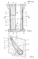
- Fig. 1 einen Querschnitt durch einen Teil einer erfindungsgemässen gekühlten Wand,
- Fig. 2 beispielsweise Ausbildungen der Buckel eines Buckelbleches,
- Fig. 3. eine Draufsicht auf ein Buckelblechteil,
- Fig. 4 einen Längsschnitt durch eine gekühlte Turbinenschaufel,
- Fig. 5 einen Querschnitt der Turbinenschaufel entlang der Schnittlinie A-A in Fig. 4,
- Fig. 6 einen Längsschnitt durch den Einlaufkanal und die erste Leitschaufelreihe einer Gasturbine.
- Gemäss Fig. 1 ist mit 1 ein Aussenblech, beispielsweise einer Brennkammer einer Gasturbine bezeichnet, zu dem im Abstand dazu ein Innenblech 2 angeordnet ist, so dass zwischen diesen beiden Blechen ein Kühlmittelraum 3 gebildet wird. Im Innern des Kühlmittelraumes 3 ist eine Trennwand 4, vorzugsweise als Buckelblech ausgebildet, angeordnet. Die einzelnen Buckel 5 des Buckelbleches sind mit dem Aussenblech 1 fest verbunden, beispielsweise verschweisst, jedoch kann auch jede andere bekannte Methode angewendet werden, wie Löten, Diffusionsbindung usw. Zwischen dem Aussenblech 1 und dem Buckelblech 4 entsteht somit ein mit Pfeilen 6 bezeichneter Strömungskanal, durch welchen das Kühlmedium fliesst und die einzelnen Buckel 5 umströmt. Zwischen dem Buckelblech 4 und dem Innenblech 2 besteht ein Druckausgleichsraum 7, in welchem der gleiche Druck vorherrscht, wie der auf die Aussenoberfläche des Aussenbleches 1 einwirkende Heissgasdruck. Eine durch das Einwirken des Heissgasdruckes auf das Aussenblech 1 und das damit verbundene Buckelblech 4 mögliche, einer Kesselspannung ähnliche Spannung wird durch den Druck im Druckausgleichsraum 7 vermieden, bzw. verringert. Zur Erzeugung des Druckes im Druckausgleichsraum 7 wird dieser vorteilhafterweise mit einer Druckquelle (nicht dargestellt) verbunden, d.h. beispielsweise bei einer Gasturbine wird der Druckausgleichsraum 7 mit einer Stufe des Verdichters verbunden.
- In der Fig. 2 sind Ausführungsbeispiele für die Ausgestaltung des Buckelbleches 4 dargestellt, wobei in der in der Zeichnung linken Abbildung einfache Buckel 5 gleichmässig über die Oberfläche des Buckelbleches 4 verteilt sind, während in der rechten Darstellung ein beidseitig mit Buckeln 5 versehenes Blech gezeigt ist, wobei diese Ausführung ein höheres Elastizitätsmodul aufweist und die Blechebene zwischen den nach oben und unten vorstehenden Buckeln 5 nahezu horizontal verläuft.
- Wie aus der Fig. 3 ersichtlich, kann die Teilung t zwischen den jeweils benachbarten Buckeln 5 des Buckelbleches 4 eine vorbestimmte Relation zum Durchmesser d der Buckel 5 aufweisen. Jedoch hängt dies in besonderem Masse von der Dicke des Buckelbleches 5 ab, wodurch gegenüber glatten Blechen eine Reduktion des Elastizitätsmoduls bis zum zwanzigfachen und mehr erzielt werden kann. Die Ausbildung der Buckelform wird sich nach den Anforderungen an die Trennwand 4 richten.
- In dem in Fig. 4 und 5 gezeigten Verwendungsbeispiel der erfindungsgemässen gekühlten Wand bei einer Turbinenschaufel besteht letztere aus einem Schaufelkern 8, welcher im Beispielsfalle teilweise hohl ausgebildet ist und einen Strömungskanal 9 einschliesst, sowie einer Fussplatte 10, einer Deckplätte 11 und einem im Abstand zum Schaufelkern 8 angeordneten, profilartig ausgebildeten Aussenmantel l', welcher funktionsmässig dem Aussenblech 1 in der Fig. 1 entspricht. Die Fussplatte 10 ist mit einem Deckel 21 verschlossen, die Deckplatte 11 ist mit dem Schaufelkern 8 verschweisst, wobei jedoch zwischen dem Schaufelkern 8 und der Deckplatte 11 eine Dehnungsfuge 12 vorgesehen ist. In der Deckplatte 11 sind weiterhin Kanäle 13 angeordnet, welche mit dem Strömungskanal 9 in Verbindung stehen. In den zwischen dem Aussenmantel 1' und dem Schaufelkern 8 gebildeten Raum ist .eine aus einem Buckelblech gebildete Trennwand 4 so angeordnet, dass zum Aussenmantel 1' hin der Kühlmittelraum 3 und zum Schaufelkern 8 hin der Druckausgleichsraum 7 gebildet wird, wobei das Buckelblech 4 an einem Ende mit der Innenoberfläche des Schaufelkernes 8 und am anderen Ende mit der Deckplatte 11 dicht verschweisst ist. Die einzelnen Buckel 5 des Buckelbleches 4 sind mit dem Aussenmantel 1' verschweisst. bzw. in einer anderen, an sich bekannten Weise, fest verbunden. Der Druckausgleichsraum 7 steht einmal über die Dehnungsfuge 12 mit einem von einer Auskleidung 14, vorzugsweise einem Wellblech umgrenzten Raum 15 und zum anderen über eine Verbindungsleitung 16 mit einer (nicht dargestellten) Druckquelle in Verbindung. Die Auskleidung 14 überdeckt einen Teil der Innenoberfläche des Strömungskanals 9.
- Bei dieser Ausbildung strömt das durch Pfeile angedeutete Kühlmedium nach Kühlung der Fussplatte 10 in den zwischen dem Aussenmantel l' und dem als Trennwand dienenden Buckelblech 4 längs der Schaufelachse. Nach Kühlung der Deckplatte 11 strömt das Kühlmedium durch den Strömungskanal 9 im Schaufelkern 8 zurück zum Schaufelfuss. Da der Aussenmantel l' von den Heissgasen beaufschlagt wird, und mit dem Buckelblech 4 starr verbunden ist, formt die aus dem Buckelblech 4 gebildete Trennwand eine Art Druckbehälter, bzw. kann als Kesselwand betrachtet werden. Ohne Gegenmassnahme würde demnach in den Blechen eine Art Kesselspannung entstehen. Durch den Druckausgleichsraum 7 zwischen dem Buckelblech 4 und dem Schaufelkern 8 wird diese Spannung vermieden. Dazu wird beispielsweise von einer (nicht dargestellten) Verdichterstufe der Gasturbine Druckluft über die Verbindungsleitung 16 in den Druckausgleichsraum 7 gefördert. Durch die dichte Verschweissung der beiden Enden des Buckelbleches 4 mit dem Schaufelkern 8, resp. der Deckplatte 11 erfolgt eine Abdichtung des Kühlmittelraumes 3 gegenüber dem Druckausgleichsraum 7, wobei jedoch die freie Dehnung des Aussenmantels l' mit dem Buckelblech 4 und der Deckplatte 11 nicht beeinträchtigt wird. Da der Schaufelkern 8 nur Dehnungen in Richtung seiner Längsachse ausführt, kann die Auskleidung 14 aus einem Wellblech bestehen. Eine derartige gekühlte Turbinenschaufel könnte auch einen masssiven Schaufelkern 8 aufweisen, wobei dann entsprechende Strömungskanäle für die Rückführung des Kühlmittels vorgesehen werden müssten. In der Regel ist bei einer gekühlten Turbinenschaufel ein Schaufelkern erforderlich, um die aus den aerodynamischen Kräften resultierenden Biegespannungen aufzunehmen. Bei Turbinenschaufeln, die keine grossen mechanischen Spannungen aufnehmen müssen, ist eine ausreichend dimensionierte Innenwand, analog zur Fig. 1 ausreichend. Weiterhin könnte das Kühlmedium auch in umgekehrter Richtung zur hier gezeigten Strömungsrichtung fliessen. Es wäre auch möglich, das Kühlmittel beispielsweise an der Anströmkante vom Fuss zur Deckplatte und an der Abströmkante von der Deckplatte zum Fuss strömen zu lassen. In diesem Falle könnte der Schaufelkern 8 massiv ausgebildet werden.
- Der in der Fig. 5 dargestellte Querschnitt durch eine gekühlte Turbinenschaufel entlang der Schnittlinie A-A in Fig. 4 zeigt andeutungsweise,'dass die Deckplatte 11 mit zusätzlichen Kühlrippen 17 versehen sein kann.
- Die Fig. 6 zeigt einen teilweisen Längsschnitt durch eine Gasturbine 18 mit der ersten Leitschaufelreihe. Bei dieser Ausbildung sind sowohl die Leitschaufeln 19, die Wärmestausegmente 20, als auch die Einströmpartie 4 und Teile des an die nicht gezeigte Brennkammer anschliessenden Heissgasgehäuses 4' mittels erfindungsgemässen gekühlten Wänden mit Aussenblech 1, Aussenmantel 1', Innenblech 2 und als Trennwänden ausgebildeten Buckelblechen 4 versehen. Die Kühlmittelzuführung zu den Kühlmittelräumen 3, sowie die Druckmittelversorgung der Druckausgleichsräume erfolgt in bekannter Weise und ist der Einfachheit halber fortgelassen worden.
- Gemäss der erfindungsgemässen gekühlten Wand ist es auf einfache Weise möglich, bei derartigen Komponenten die Wärmespannungen niedrig zu halten.
- Die Verwendung des Erfindungsgegenstandes ist auf die hier beschriebenen Beispiele nicht beschränkt, sondern könnte bei allen, hohen thermischen Beanspruchungen ausgesetzten Gegenständen verwendet werden.
Claims (12)
Applications Claiming Priority (2)
| Application Number | Priority Date | Filing Date | Title |
|---|---|---|---|
| CH1132479 | 1979-12-20 | ||
| CH11324/79 | 1979-12-20 |
Publications (2)
| Publication Number | Publication Date |
|---|---|
| EP0031174A1 true EP0031174A1 (de) | 1981-07-01 |
| EP0031174B1 EP0031174B1 (de) | 1984-08-22 |
Family
ID=4372382
Family Applications (1)
| Application Number | Title | Priority Date | Filing Date |
|---|---|---|---|
| EP80201134A Expired EP0031174B1 (de) | 1979-12-20 | 1980-12-01 | Gekühlte Gasturbinenschaufel |
Country Status (4)
| Country | Link |
|---|---|
| US (1) | US4359310A (de) |
| EP (1) | EP0031174B1 (de) |
| JP (1) | JPS56100298A (de) |
| DE (2) | DE3003347A1 (de) |
Cited By (4)
| Publication number | Priority date | Publication date | Assignee | Title |
|---|---|---|---|---|
| GB2123489A (en) * | 1982-07-12 | 1984-02-01 | Rockwell International Corp | Support a ceramic blade for a gas turbine |
| WO1998025009A1 (de) * | 1996-12-02 | 1998-06-11 | Siemens Aktiengesellschaft | Turbinenschaufel sowie verwendung in einer gasturbinenanlage |
| EP1505254A3 (de) * | 2003-08-08 | 2012-07-04 | Alstom Technology Ltd | Gasturbine und zugehöriges Kühlverfahren |
| EP3650641A1 (de) * | 2018-11-09 | 2020-05-13 | United Technologies Corporation | Schaufel mit kühlkreis durch plattformen und schaufelabschnitte |
Families Citing this family (18)
| Publication number | Priority date | Publication date | Assignee | Title |
|---|---|---|---|---|
| JPS59120704A (ja) * | 1982-12-27 | 1984-07-12 | Toshiba Corp | 超高温耐熱壁体 |
| US5704763A (en) * | 1990-08-01 | 1998-01-06 | General Electric Company | Shear jet cooling passages for internally cooled machine elements |
| US5088888A (en) * | 1990-12-03 | 1992-02-18 | General Electric Company | Shroud seal |
| US6261054B1 (en) * | 1999-01-25 | 2001-07-17 | General Electric Company | Coolable airfoil assembly |
| GB2402442B (en) * | 2003-06-04 | 2006-05-31 | Rolls Royce Plc | Cooled nozzled guide vane or turbine rotor blade platform |
| US8884182B2 (en) * | 2006-12-11 | 2014-11-11 | General Electric Company | Method of modifying the end wall contour in a turbine using laser consolidation and the turbines derived therefrom |
| US8206109B2 (en) * | 2009-03-30 | 2012-06-26 | General Electric Company | Turbine blade assemblies with thermal insulation |
| US20110110772A1 (en) * | 2009-11-11 | 2011-05-12 | Arrell Douglas J | Turbine Engine Components with Near Surface Cooling Channels and Methods of Making the Same |
| US8777569B1 (en) * | 2011-03-16 | 2014-07-15 | Florida Turbine Technologies, Inc. | Turbine vane with impingement cooling insert |
| JP5931351B2 (ja) | 2011-05-13 | 2016-06-08 | 三菱重工業株式会社 | タービン静翼 |
| US8858159B2 (en) | 2011-10-28 | 2014-10-14 | United Technologies Corporation | Gas turbine engine component having wavy cooling channels with pedestals |
| US20130318996A1 (en) * | 2012-06-01 | 2013-12-05 | General Electric Company | Cooling assembly for a bucket of a turbine system and method of cooling |
| US9638057B2 (en) | 2013-03-14 | 2017-05-02 | Rolls-Royce North American Technologies, Inc. | Augmented cooling system |
| US20150198050A1 (en) * | 2014-01-15 | 2015-07-16 | Siemens Energy, Inc. | Internal cooling system with corrugated insert forming nearwall cooling channels for airfoil usable in a gas turbine engine |
| US9771814B2 (en) * | 2015-03-09 | 2017-09-26 | United Technologies Corporation | Tolerance resistance coverplates |
| US10471542B1 (en) * | 2017-06-27 | 2019-11-12 | United States Of America As Represented By The Administrator Of Nasa | Cladding and freeform deposition for coolant channel closeout |
| US11002139B2 (en) * | 2017-12-12 | 2021-05-11 | Hamilton Sundstrand Corporation | Cooled polymer component |
| US11248479B2 (en) * | 2020-06-11 | 2022-02-15 | General Electric Company | Cast turbine nozzle having heat transfer protrusions on inner surface of leading edge |
Citations (1)
| Publication number | Priority date | Publication date | Assignee | Title |
|---|---|---|---|---|
| US2801073A (en) * | 1952-06-30 | 1957-07-30 | United Aircraft Corp | Hollow sheet metal blade or vane construction |
Family Cites Families (23)
| Publication number | Priority date | Publication date | Assignee | Title |
|---|---|---|---|---|
| FR980028A (fr) * | 1942-06-18 | 1951-05-07 | Regent | Perfectionnements apportés aux chambres de combustion |
| GB602530A (en) * | 1945-10-16 | 1948-05-28 | Bristol Aeroplane Co Ltd | Improvements in or relating to gas turbines |
| FR56235E (fr) * | 1946-07-11 | 1952-09-19 | Gen Mecanique Appliquee Soc In | Perfectionnements apportés aux moyens d'entraînement, par réaction, d'hélices ou voilures tournantes, notamment pour hélicoptères |
| GB663639A (en) * | 1948-09-24 | 1951-12-27 | Peabody Engineering Corp | Improvements in gas heaters and other heat exchangers |
| GB685769A (en) * | 1949-11-22 | 1953-01-14 | Rolls Royce | Improvements relating to compressor and turbine blading |
| GB740597A (en) * | 1953-11-07 | 1955-11-16 | Gen Motors Corp | Improvements relating to gas turbine or compressor blades |
| US2888241A (en) * | 1954-06-09 | 1959-05-26 | Stalker Corp | Fabricated cooled turbine blades |
| US2906495A (en) * | 1955-04-29 | 1959-09-29 | Eugene F Schum | Turbine blade with corrugated strut |
| US3013641A (en) * | 1957-04-29 | 1961-12-19 | Thompson Ramo Wooldridge Inc | Structural element |
| FR1177035A (fr) * | 1957-05-28 | 1959-04-20 | Snecma | Procédé et dispositif de refroidissement d'organes de machines |
| US3057597A (en) * | 1959-08-20 | 1962-10-09 | Jr Andre J Meyer | Modification and improvements to cooled blades |
| US3246469A (en) * | 1963-08-22 | 1966-04-19 | Bristol Siddelcy Engines Ltd | Cooling of aerofoil members |
| FR1502738A (fr) * | 1966-07-28 | 1967-11-24 | Snecma | Procédé et dispositif de refroidissement applicable notamment aux aubes de turbine |
| US3446481A (en) * | 1967-03-24 | 1969-05-27 | Gen Electric | Liquid cooled turbine rotor |
| DE1601613A1 (de) * | 1967-08-03 | 1970-12-17 | Motoren Turbinen Union | Turbinenschaufel,insbesondere Turbinenleitschaufel fuer Gasturbinentriebwerke |
| US3700348A (en) * | 1968-08-13 | 1972-10-24 | Gen Electric | Turbomachinery blade structure |
| AU1230570A (en) * | 1969-04-02 | 1971-09-16 | United Aircraft Corporation | Joint construction ina combustion chamber and method of making therefor |
| IL33995A0 (en) * | 1969-04-02 | 1970-05-21 | United Aircraft Corp | Wall structure and method of manufacturing it |
| DE2003206A1 (de) * | 1970-01-24 | 1971-08-12 | Daimler Benz Ag | Waermetauschersystem |
| BE767972A (fr) * | 1970-06-04 | 1971-12-02 | Westinghouse Electric Corp | Piece encastree pour le refroidissement d'une aube de turbine |
| GB1332679A (en) * | 1970-11-12 | 1973-10-03 | Gen Electric | Turbomachinery blade structure |
| US3767322A (en) * | 1971-07-30 | 1973-10-23 | Westinghouse Electric Corp | Internal cooling for turbine vanes |
| US4142831A (en) * | 1977-06-15 | 1979-03-06 | General Electric Company | Liquid-cooled turbine bucket with enhanced heat transfer performance |
-
1980
- 1980-01-31 DE DE19803003347 patent/DE3003347A1/de not_active Withdrawn
- 1980-09-29 US US06/191,382 patent/US4359310A/en not_active Expired - Lifetime
- 1980-12-01 EP EP80201134A patent/EP0031174B1/de not_active Expired
- 1980-12-01 DE DE8080201134T patent/DE3069038D1/de not_active Expired
- 1980-12-19 JP JP17909180A patent/JPS56100298A/ja active Granted
Patent Citations (1)
| Publication number | Priority date | Publication date | Assignee | Title |
|---|---|---|---|---|
| US2801073A (en) * | 1952-06-30 | 1957-07-30 | United Aircraft Corp | Hollow sheet metal blade or vane construction |
Cited By (5)
| Publication number | Priority date | Publication date | Assignee | Title |
|---|---|---|---|---|
| GB2123489A (en) * | 1982-07-12 | 1984-02-01 | Rockwell International Corp | Support a ceramic blade for a gas turbine |
| WO1998025009A1 (de) * | 1996-12-02 | 1998-06-11 | Siemens Aktiengesellschaft | Turbinenschaufel sowie verwendung in einer gasturbinenanlage |
| EP1505254A3 (de) * | 2003-08-08 | 2012-07-04 | Alstom Technology Ltd | Gasturbine und zugehöriges Kühlverfahren |
| EP3650641A1 (de) * | 2018-11-09 | 2020-05-13 | United Technologies Corporation | Schaufel mit kühlkreis durch plattformen und schaufelabschnitte |
| US11028700B2 (en) | 2018-11-09 | 2021-06-08 | Raytheon Technologies Corporation | Airfoil with cooling passage circuit through platforms and airfoil section |
Also Published As
| Publication number | Publication date |
|---|---|
| EP0031174B1 (de) | 1984-08-22 |
| US4359310A (en) | 1982-11-16 |
| DE3069038D1 (en) | 1984-09-27 |
| DE3003347A1 (de) | 1981-06-25 |
| JPS56100298A (en) | 1981-08-12 |
| JPH0252196B2 (de) | 1990-11-09 |
Similar Documents
| Publication | Publication Date | Title |
|---|---|---|
| EP0031174A1 (de) | Gekühlte Gasturbinenschaufel | |
| DE69825959T2 (de) | Vorrichtung zum dichten der leitschaufeln von gasturbinen | |
| DE2555049C2 (de) | Gekühlte Turbinenschaufel | |
| DE3345263C2 (de) | Gekühlte Turbinenschaufel | |
| DE2320581C2 (de) | Gasturbine mit luftgekühlten Turbinenlaufschaufeln | |
| DE1946535C3 (de) | Bauteil für ein Gasturbinentriebwerk | |
| DE3789514T2 (de) | Gekühlte Gasturbinenschaufel. | |
| DE69933601T2 (de) | Gasturbine | |
| DE69503616T2 (de) | Doppelte kühlluftversorgung des deckbandes einer turbinenleitschaufel | |
| EP1320661B1 (de) | Gasturbinenschaufel | |
| DE69505882T2 (de) | Kühlung für die Blattspitzen einer Turbine | |
| DE69324506T2 (de) | Gekühlte turbinenschaufel | |
| DE2241194C3 (de) | Strömungsmaschinenschaufel mit inneren Kühlkanälen | |
| DE69019833T2 (de) | Turbolader mit verstellbaren Leitschaufeln. | |
| EP0199321B1 (de) | Wärmetauscher | |
| DE19809008A1 (de) | Gasturbinenschaufel | |
| DE69118098T2 (de) | Abdeckring für Bolzenköpfe | |
| DE2553193A1 (de) | Bohrungsschaufeleinrichtung fuer turbinenschaufeln mit bohrungseintrittskuehlung | |
| DE19814680A1 (de) | Gekühlte Gasturbinen-Laufschaufel | |
| DE1601555A1 (de) | Gekuehlter Turbinenleitkranz fuer bei hohen Temperaturen arbeitende Turbinen | |
| EP1112439A1 (de) | Turbinenschaufel | |
| DE3248163A1 (de) | Kuehlbare schaufel | |
| DE10296563T5 (de) | Rotationsmaschine mit Dichtungsvorrichtung | |
| DE1476804A1 (de) | Turbinenschaufel mit Tragflaechenprofil | |
| CH701041A2 (de) | Turbinenleitapparat mit Seitenwandkühlplenum. |
Legal Events
| Date | Code | Title | Description |
|---|---|---|---|
| PUAI | Public reference made under article 153(3) epc to a published international application that has entered the european phase |
Free format text: ORIGINAL CODE: 0009012 |
|
| AK | Designated contracting states |
Designated state(s): CH DE FR GB IT NL SE |
|
| RAP1 | Party data changed (applicant data changed or rights of an application transferred) |
Owner name: BBC AKTIENGESELLSCHAFT BROWN, BOVERI & CIE. |
|
| 17P | Request for examination filed |
Effective date: 19811204 |
|
| ITF | It: translation for a ep patent filed | ||
| GRAA | (expected) grant |
Free format text: ORIGINAL CODE: 0009210 |
|
| AK | Designated contracting states |
Designated state(s): CH DE FR GB IT LI NL SE |
|
| REF | Corresponds to: |
Ref document number: 3069038 Country of ref document: DE Date of ref document: 19840927 |
|
| ET | Fr: translation filed | ||
| PLBE | No opposition filed within time limit |
Free format text: ORIGINAL CODE: 0009261 |
|
| STAA | Information on the status of an ep patent application or granted ep patent |
Free format text: STATUS: NO OPPOSITION FILED WITHIN TIME LIMIT |
|
| 26N | No opposition filed | ||
| ITTA | It: last paid annual fee | ||
| PGFP | Annual fee paid to national office [announced via postgrant information from national office to epo] |
Ref country code: NL Payment date: 19901231 Year of fee payment: 11 |
|
| PGFP | Annual fee paid to national office [announced via postgrant information from national office to epo] |
Ref country code: CH Payment date: 19910315 Year of fee payment: 11 |
|
| PG25 | Lapsed in a contracting state [announced via postgrant information from national office to epo] |
Ref country code: LI Effective date: 19911231 Ref country code: CH Effective date: 19911231 |
|
| PG25 | Lapsed in a contracting state [announced via postgrant information from national office to epo] |
Ref country code: NL Effective date: 19920701 |
|
| NLV4 | Nl: lapsed or anulled due to non-payment of the annual fee | ||
| REG | Reference to a national code |
Ref country code: CH Ref legal event code: PL |
|
| EAL | Se: european patent in force in sweden |
Ref document number: 80201134.6 |
|
| PGFP | Annual fee paid to national office [announced via postgrant information from national office to epo] |
Ref country code: SE Payment date: 19971124 Year of fee payment: 18 |
|
| PG25 | Lapsed in a contracting state [announced via postgrant information from national office to epo] |
Ref country code: SE Free format text: LAPSE BECAUSE OF NON-PAYMENT OF DUE FEES Effective date: 19981202 |
|
| PGFP | Annual fee paid to national office [announced via postgrant information from national office to epo] |
Ref country code: GB Payment date: 19991112 Year of fee payment: 20 |
|
| PGFP | Annual fee paid to national office [announced via postgrant information from national office to epo] |
Ref country code: DE Payment date: 19991123 Year of fee payment: 20 |
|
| PGFP | Annual fee paid to national office [announced via postgrant information from national office to epo] |
Ref country code: FR Payment date: 19991227 Year of fee payment: 20 |
|
| PG25 | Lapsed in a contracting state [announced via postgrant information from national office to epo] |
Ref country code: GB Free format text: LAPSE BECAUSE OF EXPIRATION OF PROTECTION Effective date: 20001130 |
|
| REG | Reference to a national code |
Ref country code: GB Ref legal event code: PE20 Effective date: 20001130 |