EP0030895B1 - Procédé de correction de la défocalisation transversale d'un paraboloide et dispositif correspondant de correction d'antenne parabolique - Google Patents
Procédé de correction de la défocalisation transversale d'un paraboloide et dispositif correspondant de correction d'antenne parabolique Download PDFInfo
- Publication number
- EP0030895B1 EP0030895B1 EP80401778A EP80401778A EP0030895B1 EP 0030895 B1 EP0030895 B1 EP 0030895B1 EP 80401778 A EP80401778 A EP 80401778A EP 80401778 A EP80401778 A EP 80401778A EP 0030895 B1 EP0030895 B1 EP 0030895B1
- Authority
- EP
- European Patent Office
- Prior art keywords
- paraboloid
- platform
- defocusing
- source
- articulated
- Prior art date
- Legal status (The legal status is an assumption and is not a legal conclusion. Google has not performed a legal analysis and makes no representation as to the accuracy of the status listed.)
- Expired
Links
- 238000000034 method Methods 0.000 title claims abstract description 16
- 238000004804 winding Methods 0.000 claims description 8
- 239000004020 conductor Substances 0.000 claims 2
- 238000010586 diagram Methods 0.000 description 7
- 238000006073 displacement reaction Methods 0.000 description 5
- 208000031968 Cadaver Diseases 0.000 description 3
- 241000826860 Trapezium Species 0.000 description 3
- 230000006978 adaptation Effects 0.000 description 3
- 241001455273 Tetrapoda Species 0.000 description 2
- 230000005855 radiation Effects 0.000 description 2
- PCTMTFRHKVHKIS-BMFZQQSSSA-N (1s,3r,4e,6e,8e,10e,12e,14e,16e,18s,19r,20r,21s,25r,27r,30r,31r,33s,35r,37s,38r)-3-[(2r,3s,4s,5s,6r)-4-amino-3,5-dihydroxy-6-methyloxan-2-yl]oxy-19,25,27,30,31,33,35,37-octahydroxy-18,20,21-trimethyl-23-oxo-22,39-dioxabicyclo[33.3.1]nonatriaconta-4,6,8,10 Chemical compound C1C=C2C[C@@H](OS(O)(=O)=O)CC[C@]2(C)[C@@H]2[C@@H]1[C@@H]1CC[C@H]([C@H](C)CCCC(C)C)[C@@]1(C)CC2.O[C@H]1[C@@H](N)[C@H](O)[C@@H](C)O[C@H]1O[C@H]1/C=C/C=C/C=C/C=C/C=C/C=C/C=C/[C@H](C)[C@@H](O)[C@@H](C)[C@H](C)OC(=O)C[C@H](O)C[C@H](O)CC[C@@H](O)[C@H](O)C[C@H](O)C[C@](O)(C[C@H](O)[C@H]2C(O)=O)O[C@H]2C1 PCTMTFRHKVHKIS-BMFZQQSSSA-N 0.000 description 1
- 206010010071 Coma Diseases 0.000 description 1
- 230000033228 biological regulation Effects 0.000 description 1
- 230000008878 coupling Effects 0.000 description 1
- 238000010168 coupling process Methods 0.000 description 1
- 238000005859 coupling reaction Methods 0.000 description 1
- 230000007423 decrease Effects 0.000 description 1
- 230000007547 defect Effects 0.000 description 1
- 238000001514 detection method Methods 0.000 description 1
- 230000005672 electromagnetic field Effects 0.000 description 1
- 238000009434 installation Methods 0.000 description 1
- 230000007246 mechanism Effects 0.000 description 1
- 230000000135 prohibitive effect Effects 0.000 description 1
- 230000000717 retained effect Effects 0.000 description 1
Images


Classifications
-
- H—ELECTRICITY
- H01—ELECTRIC ELEMENTS
- H01Q—ANTENNAS, i.e. RADIO AERIALS
- H01Q1/00—Details of, or arrangements associated with, antennas
- H01Q1/12—Supports; Mounting means
- H01Q1/18—Means for stabilising antennas on an unstable platform
-
- H—ELECTRICITY
- H01—ELECTRIC ELEMENTS
- H01Q—ANTENNAS, i.e. RADIO AERIALS
- H01Q1/00—Details of, or arrangements associated with, antennas
- H01Q1/12—Supports; Mounting means
- H01Q1/125—Means for positioning
- H01Q1/1264—Adjusting different parts or elements of an aerial unit
Definitions
- the orientation of a beam of satellite dishes and a satellite dish in general can be obtained in different ways.
- the assembly When the source is rigidly linked to the paraboloid, the assembly can be pivoted around the reference axes.
- This solution is commonly used on surveillance radars for example.
- this satellite is roughly stabilized on the orientation axis while a fine pointing system brings the focus of the dish in the intended direction.
- the antenna is linked to a platform that can be oriented relative to the satellite and the orientation device essentially consists of a particular electromagnetic system which has the advantage of eliminating friction generating disturbing torques and which has been described in another European patent application of the Applicant EP-A-0 015 829 entitled "Electromagnetic method for adjusting the orientation of a platform”.
- the source-paraboloid assembly can be symbolically represented by a truncated pyramid with a triangular (or square) base in which the fixed source would be at the top of said pyramid and the director of the paraboloid perpendicular to the plane of the truncated part; the base being for its part subject to a fixed part.
- the truncated part being linked to this base by axially deformable elements oriented along the edges, it is possible to obtain, by rotation of the connection points, a displacement of the sides of said truncated part which then takes place substantially in the plane of the lateral faces of said pyramid thus bringing a minimum difference between the focus and the source.
- the invention proposes a method for correcting the transverse defocusing of a paraboloid which does not have any of the drawbacks described above.
- the paraboloid is supported on a first platform articulated transversely according to a deformable trapezoid and said first platform is itself articulated orthogonally on a second platform articulated according to a deformable trapezium linked to the fixed base.
- the paraboloid 1 is linked by the frame 3 to the source S of the horn 2 located at the focal point F and the director Z is oriented by pivoting of the body 4 around the axes XX 'and / or YY'.
- the dish is linked by the frame 3 'to the source S of the horn 2' located at the focal point F and the director Z is oriented by pivoting of the ball 5 around the axes XX 'and / or YY' .
- phase center is in S, the direction SO making with OZ an angle 0, it follows a phase variation ⁇ (y) on the aperture AB which causes a deviation of the beam ... and an asymmetry in the radiation pattern ..., an important secondary lobe appears on the side opposite the deviation (coma lobe).
- the body 4 "of the satellite is oriented along OZ by its own attitude correction means while the pointing which, according to OZ, is obtained using appropriate means by correction around axes XX 'and / or YY' according to the articulation point 0 located at 6, which shows the above-mentioned transverse defocus defect.
- the invention proposes a method for correcting the transverse defocusing of a parabolic antenna which does not have the aforementioned drawbacks.
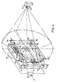
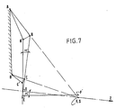
- the focal point F of the paraboloid is maintained in the immediate vicinity of the source S by the fact that the point 0 is moved transversely to the pointing axis SZ, using a device shown diagrammatically on the FIG. 4 and the principle of which is set out in FIG. 5 or as a variant in FIGS. 6 and 7.
- the paraboloid 10 with a focal point F centered in S is connected by a pylon 9 to a first platform 18 in a trapezoid articulated around the axes XX ′ according to A, B, C and D of FIG. 5.
- the sides AB and CD are arranged at rest in the direction of the confused points F and S.
- the first platform is articulated on a second trapezoid platform 19 articulated on the base 12 around the axes Y - Y 'along A, B, C and D, FIG. 5.
- the sides AB and CD are also arranged at rest in the direction of the confused points F and S.
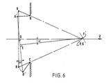
- the rotation of the straight line BC around the point F is obtained by deformation of the articulated trapezium ABCD and this deformation A ⁇ B '.
- C'D makes it possible to combine rotation and translation of the line BC so that the displacements of the point F on the perpendicular bisector of BC remain very small during the movement.
- this point F will move in F 'by a quantity d ⁇ k ⁇ 2 , that is to say by a 2nd order term in ⁇ if, of course, AB and DC initially converge all two towards this point F.
- Figures 5 and 6 show the cases where BC and AD are initially parallel.
- electromagnetic devices can be of the type such as those described in the aforementioned patent application EP-A-0015829, identified 16-17 in FIG. 4 and shown on a larger scale in FIG. 8 and for which the operating principle is recalled below.
- Each platform 18 or 19 therefore carries a flat winding situated in its plane and the strands of which are in the direction of movement.
- These coils 21 and 22 are connected to a servo unit 23 connected to a deflection detector 7 (not shown).
- each winding sees the direction of current flow established according to, for example, the arrows in FIG. 8.
- Each coil is overlapped by a pair of magnets 24-25, of reverse polarity, which are fixed to the fixed base 12 by a support 26.
- the arrangement of the magnets and the coils can be reversed without changing the result.
- each platform 18 or 19 will therefore move in the magnetic field in the direction of arrows f1 or f2 with more or less amplitude and this in accordance with the law of LAPLACE .
- the source of emission and / or reception is, according to the known manner, a horn in waveguide 8 with progressively increasing section, secured to the fixed base.
- the paraboloid constitutes the reflector of a parabolic antenna which can be implemented, through the invention, in all the fields where it is usually used from the moment when the source S is not subject to the director passing through foyer F.
Landscapes
- Variable-Direction Aerials And Aerial Arrays (AREA)
- Aerials With Secondary Devices (AREA)
- Mounting And Adjusting Of Optical Elements (AREA)
- Details Of Aerials (AREA)
Priority Applications (1)
| Application Number | Priority Date | Filing Date | Title |
|---|---|---|---|
| AT80401778T ATE5285T1 (de) | 1979-12-18 | 1980-12-11 | Verfahren zur korrektur der querentfokussierung einer parabolantenne und vorrichtung zur korrektur einer parabolantenne. |
Applications Claiming Priority (2)
| Application Number | Priority Date | Filing Date | Title |
|---|---|---|---|
| FR7930957A FR2472284A1 (fr) | 1979-12-18 | 1979-12-18 | Procede de correction de la defocalisation transversale d'un paraboloide et dispositif correspondant de correction d'antenne parabolique |
| FR7930957 | 1979-12-18 |
Publications (2)
| Publication Number | Publication Date |
|---|---|
| EP0030895A1 EP0030895A1 (fr) | 1981-06-24 |
| EP0030895B1 true EP0030895B1 (fr) | 1983-11-09 |
Family
ID=9232882
Family Applications (1)
| Application Number | Title | Priority Date | Filing Date |
|---|---|---|---|
| EP80401778A Expired EP0030895B1 (fr) | 1979-12-18 | 1980-12-11 | Procédé de correction de la défocalisation transversale d'un paraboloide et dispositif correspondant de correction d'antenne parabolique |
Country Status (7)
| Country | Link |
|---|---|
| US (1) | US4365252A (show.php) |
| EP (1) | EP0030895B1 (show.php) |
| JP (1) | JPS5694805A (show.php) |
| AT (1) | ATE5285T1 (show.php) |
| CA (1) | CA1156754A (show.php) |
| DE (1) | DE3065561D1 (show.php) |
| FR (1) | FR2472284A1 (show.php) |
Families Citing this family (6)
| Publication number | Priority date | Publication date | Assignee | Title |
|---|---|---|---|---|
| FR2502404A1 (fr) * | 1981-03-20 | 1982-09-24 | Matra | Dispositif de montage articule, notamment d'un sous-ensemble de satellite artificiel |
| FR2523375A1 (fr) * | 1982-03-10 | 1983-09-16 | Europ Agence Spatiale | Dispositif de compensation des distorsions des reflecteurs pour antennes de reception et/ou transmission d'ondes a faisceaux multiples |
| FR2543697B1 (fr) * | 1983-03-30 | 1985-08-23 | Aerospatiale | Procede et dispositif de suspension et d'entrainement d'un miroir oscillant de telescope spatial |
| DE9014875U1 (de) * | 1990-10-27 | 1991-01-10 | Kabelmetal Electro Gmbh, 30179 Hannover | Antenne mit einem parabolischen Reflektor |
| US7118658B2 (en) * | 2002-05-21 | 2006-10-10 | Semitool, Inc. | Electroplating reactor |
| TW202306722A (zh) | 2021-02-22 | 2023-02-16 | 美商外世界股份有限公司 | 具有機械臂波導的基於微波的採礦系統及方法 |
Citations (1)
| Publication number | Priority date | Publication date | Assignee | Title |
|---|---|---|---|---|
| EP0015829A1 (fr) * | 1979-02-28 | 1980-09-17 | AEROSPATIALE Société Nationale Industrielle | Procédé électromagnétique pour régler l'orientation d'une plate-forme et plate-forme mettant en oeuvre ce procédé |
Family Cites Families (7)
| Publication number | Priority date | Publication date | Assignee | Title |
|---|---|---|---|---|
| GB905440A (en) * | 1957-12-18 | 1962-09-05 | Gen Electric Co Ltd | Improvements in or relating to position control arrangements and aerial systems including such arrangements |
| US3166750A (en) * | 1961-02-14 | 1965-01-19 | Raytheon Co | Antenna intersecting-orthogonal-axes gimbal mount utilizing rotary bearings for two axes and push-pull linkage for third axis |
| US3262321A (en) * | 1963-09-16 | 1966-07-26 | Jr George E Moul | Two-rod seeker head |
| DE1273625B (de) * | 1964-04-03 | 1968-07-25 | Boelkow Gmbh | Nachrichten-Satellit mit einem Richtfunksystem und mit einer Konfiguration in Form einer Hantel |
| US3374977A (en) * | 1966-06-09 | 1968-03-26 | Collins Radio Co | Antenna positioner |
| US3565515A (en) * | 1967-12-12 | 1971-02-23 | Perkin Elmer Corp | Mounts for optical elements |
| JPS5028148B1 (show.php) * | 1969-11-28 | 1975-09-12 |
-
1979
- 1979-12-18 FR FR7930957A patent/FR2472284A1/fr active Granted
-
1980
- 1980-12-02 CA CA000365921A patent/CA1156754A/en not_active Expired
- 1980-12-03 US US06/212,663 patent/US4365252A/en not_active Expired - Lifetime
- 1980-12-11 AT AT80401778T patent/ATE5285T1/de active
- 1980-12-11 EP EP80401778A patent/EP0030895B1/fr not_active Expired
- 1980-12-11 DE DE8080401778T patent/DE3065561D1/de not_active Expired
- 1980-12-16 JP JP17796380A patent/JPS5694805A/ja active Granted
Patent Citations (1)
| Publication number | Priority date | Publication date | Assignee | Title |
|---|---|---|---|---|
| EP0015829A1 (fr) * | 1979-02-28 | 1980-09-17 | AEROSPATIALE Société Nationale Industrielle | Procédé électromagnétique pour régler l'orientation d'une plate-forme et plate-forme mettant en oeuvre ce procédé |
Also Published As
| Publication number | Publication date |
|---|---|
| EP0030895A1 (fr) | 1981-06-24 |
| DE3065561D1 (en) | 1983-12-15 |
| CA1156754A (en) | 1983-11-08 |
| ATE5285T1 (de) | 1983-11-15 |
| FR2472284A1 (fr) | 1981-06-26 |
| JPS5694805A (en) | 1981-07-31 |
| JPH0136282B2 (show.php) | 1989-07-31 |
| US4365252A (en) | 1982-12-21 |
| FR2472284B1 (show.php) | 1981-12-24 |
Similar Documents
| Publication | Publication Date | Title |
|---|---|---|
| EP0656671B1 (fr) | Antenne orientable avec conservation des axes de polarisation | |
| FR2669887A1 (fr) | Procede de controle d'attitude en tangage d'un satellite grace a la pression de radiation solaire et satellite adapte a sa mise en óoeuvre. | |
| EP0030895B1 (fr) | Procédé de correction de la défocalisation transversale d'un paraboloide et dispositif correspondant de correction d'antenne parabolique | |
| FR2947103A1 (fr) | Antenne a flexibilite de mission, satellite comportant une telle antenne et procede de commande du changement de mission d'une telle antenne | |
| FR2814216A1 (fr) | Dispositif d'orientation et systeme d'orientation embarque | |
| FR2598339A1 (fr) | Antennes a reflecteurs paraboliques et leur procede d'obtention | |
| FR2825478A1 (fr) | Dispositif de focalisation d'ondes electromagnetiques | |
| EP0548876B1 (fr) | Antenne active "offset" à double réflecteurs | |
| EP3457489B1 (fr) | Joint tournant pour une antenne rotative et antenne rotative comportant un tel joint | |
| EP4313768A1 (fr) | Satellite réflecteur et ensemble satellitaire comprenant un tel satellite | |
| EP3675278B1 (fr) | Antenne multifaisceaux à pointage réglable | |
| CA2359631A1 (en) | Side-fed offset cassegrain antenna with main reflector gimbal | |
| EP4025502B1 (fr) | Procédé de fabrication d'un satellite à partir d'une configuration générique d'éléments antennaires | |
| EP0072316A1 (fr) | Antenne à balayage électronique à accès multiples et radar comportant une telle antenne | |
| FR2646023A1 (fr) | Dispositif de pointage d'antenne, satellite equipe d'un tel dispositif et procede de pointage d'antenne utilisant un tel dispositif | |
| EP3457490B1 (fr) | Antenne biaxe comportant une première partie fixe, une deuxième partie rotative et un joint tournant | |
| EP0032081B1 (fr) | Antenne à faisceau orientable pour satellite de télécommunications | |
| FR2760900A1 (fr) | Antenne pour satellite a defilement | |
| FR2578058A1 (fr) | Procede et dispositif de poursuite d'un satellite de communication | |
| FR2850174A1 (fr) | Systemes asservis d'actionnement | |
| FR2535479A1 (fr) | Dispositif d'orientation sans frottements solides, et application a un vehicule spatial | |
| EP3220181B1 (fr) | Systeme optique hybride a encombrement reduit pour antenne reseau imageur | |
| CA1257692A (fr) | Dispositif d'orientation d'une antenne permettant de realiser un balayage selon deux directions orthogonales | |
| EP1377863A1 (fr) | Dispositif de montage et de correction de la position d'un miroir s'etendant dans l'ombre du miroir et systeme optique equipe de ce dispositif | |
| FR2581615A1 (fr) | Satellite de telecommunications geostationnaire |
Legal Events
| Date | Code | Title | Description |
|---|---|---|---|
| PUAI | Public reference made under article 153(3) epc to a published international application that has entered the european phase |
Free format text: ORIGINAL CODE: 0009012 |
|
| AK | Designated contracting states |
Designated state(s): AT BE CH DE GB IT NL SE |
|
| 17P | Request for examination filed |
Effective date: 19810711 |
|
| ITF | It: translation for a ep patent filed | ||
| GRAA | (expected) grant |
Free format text: ORIGINAL CODE: 0009210 |
|
| AK | Designated contracting states |
Designated state(s): AT BE CH DE GB IT LI NL SE |
|
| REF | Corresponds to: |
Ref document number: 5285 Country of ref document: AT Date of ref document: 19831115 Kind code of ref document: T |
|
| REF | Corresponds to: |
Ref document number: 3065561 Country of ref document: DE Date of ref document: 19831215 |
|
| PLBE | No opposition filed within time limit |
Free format text: ORIGINAL CODE: 0009261 |
|
| STAA | Information on the status of an ep patent application or granted ep patent |
Free format text: STATUS: NO OPPOSITION FILED WITHIN TIME LIMIT |
|
| 26N | No opposition filed | ||
| ITTA | It: last paid annual fee | ||
| PGFP | Annual fee paid to national office [announced via postgrant information from national office to epo] |
Ref country code: GB Payment date: 19941130 Year of fee payment: 15 |
|
| PGFP | Annual fee paid to national office [announced via postgrant information from national office to epo] |
Ref country code: SE Payment date: 19941216 Year of fee payment: 15 |
|
| PGFP | Annual fee paid to national office [announced via postgrant information from national office to epo] |
Ref country code: CH Payment date: 19941219 Year of fee payment: 15 |
|
| PGFP | Annual fee paid to national office [announced via postgrant information from national office to epo] |
Ref country code: AT Payment date: 19941230 Year of fee payment: 15 |
|
| PGFP | Annual fee paid to national office [announced via postgrant information from national office to epo] |
Ref country code: NL Payment date: 19941231 Year of fee payment: 15 |
|
| PGFP | Annual fee paid to national office [announced via postgrant information from national office to epo] |
Ref country code: BE Payment date: 19950110 Year of fee payment: 15 |
|
| EAL | Se: european patent in force in sweden |
Ref document number: 80401778.8 |
|
| PGFP | Annual fee paid to national office [announced via postgrant information from national office to epo] |
Ref country code: DE Payment date: 19950131 Year of fee payment: 15 |
|
| PG25 | Lapsed in a contracting state [announced via postgrant information from national office to epo] |
Ref country code: GB Effective date: 19951211 Ref country code: AT Effective date: 19951211 |
|
| PG25 | Lapsed in a contracting state [announced via postgrant information from national office to epo] |
Ref country code: SE Effective date: 19951212 |
|
| PG25 | Lapsed in a contracting state [announced via postgrant information from national office to epo] |
Ref country code: LI Effective date: 19951231 Ref country code: CH Effective date: 19951231 Ref country code: BE Effective date: 19951231 |
|
| BERE | Be: lapsed |
Owner name: SOC. NATIONALE INDUSTRIELLE AEROSPATIALE Effective date: 19951231 |
|
| PG25 | Lapsed in a contracting state [announced via postgrant information from national office to epo] |
Ref country code: NL Effective date: 19960701 |
|
| GBPC | Gb: european patent ceased through non-payment of renewal fee |
Effective date: 19951211 |
|
| REG | Reference to a national code |
Ref country code: CH Ref legal event code: PL |
|
| NLV4 | Nl: lapsed or anulled due to non-payment of the annual fee |
Effective date: 19960701 |
|
| PG25 | Lapsed in a contracting state [announced via postgrant information from national office to epo] |
Ref country code: DE Effective date: 19960903 |