EP0030895B1 - Method of correcting the cross-defocusing of a paraboloid and matching device for correcting a parabolic antenna - Google Patents
Method of correcting the cross-defocusing of a paraboloid and matching device for correcting a parabolic antenna Download PDFInfo
- Publication number
- EP0030895B1 EP0030895B1 EP80401778A EP80401778A EP0030895B1 EP 0030895 B1 EP0030895 B1 EP 0030895B1 EP 80401778 A EP80401778 A EP 80401778A EP 80401778 A EP80401778 A EP 80401778A EP 0030895 B1 EP0030895 B1 EP 0030895B1
- Authority
- EP
- European Patent Office
- Prior art keywords
- paraboloid
- platform
- defocusing
- source
- articulated
- Prior art date
- Legal status (The legal status is an assumption and is not a legal conclusion. Google has not performed a legal analysis and makes no representation as to the accuracy of the status listed.)
- Expired
Links
Images


Classifications
-
- H—ELECTRICITY
- H01—ELECTRIC ELEMENTS
- H01Q—ANTENNAS, i.e. RADIO AERIALS
- H01Q1/00—Details of, or arrangements associated with, antennas
- H01Q1/12—Supports; Mounting means
- H01Q1/18—Means for stabilising antennas on an unstable platform
-
- H—ELECTRICITY
- H01—ELECTRIC ELEMENTS
- H01Q—ANTENNAS, i.e. RADIO AERIALS
- H01Q1/00—Details of, or arrangements associated with, antennas
- H01Q1/12—Supports; Mounting means
- H01Q1/125—Means for positioning
- H01Q1/1264—Adjusting different parts or elements of an aerial unit
Definitions
- the orientation of a beam of satellite dishes and a satellite dish in general can be obtained in different ways.
- the assembly When the source is rigidly linked to the paraboloid, the assembly can be pivoted around the reference axes.
- This solution is commonly used on surveillance radars for example.
- this satellite is roughly stabilized on the orientation axis while a fine pointing system brings the focus of the dish in the intended direction.
- the antenna is linked to a platform that can be oriented relative to the satellite and the orientation device essentially consists of a particular electromagnetic system which has the advantage of eliminating friction generating disturbing torques and which has been described in another European patent application of the Applicant EP-A-0 015 829 entitled "Electromagnetic method for adjusting the orientation of a platform”.
- the source-paraboloid assembly can be symbolically represented by a truncated pyramid with a triangular (or square) base in which the fixed source would be at the top of said pyramid and the director of the paraboloid perpendicular to the plane of the truncated part; the base being for its part subject to a fixed part.
- the truncated part being linked to this base by axially deformable elements oriented along the edges, it is possible to obtain, by rotation of the connection points, a displacement of the sides of said truncated part which then takes place substantially in the plane of the lateral faces of said pyramid thus bringing a minimum difference between the focus and the source.
- the invention proposes a method for correcting the transverse defocusing of a paraboloid which does not have any of the drawbacks described above.
- the paraboloid is supported on a first platform articulated transversely according to a deformable trapezoid and said first platform is itself articulated orthogonally on a second platform articulated according to a deformable trapezium linked to the fixed base.
- the paraboloid 1 is linked by the frame 3 to the source S of the horn 2 located at the focal point F and the director Z is oriented by pivoting of the body 4 around the axes XX 'and / or YY'.
- the dish is linked by the frame 3 'to the source S of the horn 2' located at the focal point F and the director Z is oriented by pivoting of the ball 5 around the axes XX 'and / or YY' .
- phase center is in S, the direction SO making with OZ an angle 0, it follows a phase variation ⁇ (y) on the aperture AB which causes a deviation of the beam ... and an asymmetry in the radiation pattern ..., an important secondary lobe appears on the side opposite the deviation (coma lobe).
- the body 4 "of the satellite is oriented along OZ by its own attitude correction means while the pointing which, according to OZ, is obtained using appropriate means by correction around axes XX 'and / or YY' according to the articulation point 0 located at 6, which shows the above-mentioned transverse defocus defect.
- the invention proposes a method for correcting the transverse defocusing of a parabolic antenna which does not have the aforementioned drawbacks.
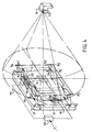
- the focal point F of the paraboloid is maintained in the immediate vicinity of the source S by the fact that the point 0 is moved transversely to the pointing axis SZ, using a device shown diagrammatically on the FIG. 4 and the principle of which is set out in FIG. 5 or as a variant in FIGS. 6 and 7.
- the paraboloid 10 with a focal point F centered in S is connected by a pylon 9 to a first platform 18 in a trapezoid articulated around the axes XX ′ according to A, B, C and D of FIG. 5.
- the sides AB and CD are arranged at rest in the direction of the confused points F and S.
- the first platform is articulated on a second trapezoid platform 19 articulated on the base 12 around the axes Y - Y 'along A, B, C and D, FIG. 5.
- the sides AB and CD are also arranged at rest in the direction of the confused points F and S.
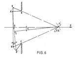
- the rotation of the straight line BC around the point F is obtained by deformation of the articulated trapezium ABCD and this deformation A ⁇ B '.
- C'D makes it possible to combine rotation and translation of the line BC so that the displacements of the point F on the perpendicular bisector of BC remain very small during the movement.
- this point F will move in F 'by a quantity d ⁇ k ⁇ 2 , that is to say by a 2nd order term in ⁇ if, of course, AB and DC initially converge all two towards this point F.
- Figures 5 and 6 show the cases where BC and AD are initially parallel.
- electromagnetic devices can be of the type such as those described in the aforementioned patent application EP-A-0015829, identified 16-17 in FIG. 4 and shown on a larger scale in FIG. 8 and for which the operating principle is recalled below.
- Each platform 18 or 19 therefore carries a flat winding situated in its plane and the strands of which are in the direction of movement.
- These coils 21 and 22 are connected to a servo unit 23 connected to a deflection detector 7 (not shown).
- each winding sees the direction of current flow established according to, for example, the arrows in FIG. 8.
- Each coil is overlapped by a pair of magnets 24-25, of reverse polarity, which are fixed to the fixed base 12 by a support 26.
- the arrangement of the magnets and the coils can be reversed without changing the result.
- each platform 18 or 19 will therefore move in the magnetic field in the direction of arrows f1 or f2 with more or less amplitude and this in accordance with the law of LAPLACE .
- the source of emission and / or reception is, according to the known manner, a horn in waveguide 8 with progressively increasing section, secured to the fixed base.
- the paraboloid constitutes the reflector of a parabolic antenna which can be implemented, through the invention, in all the fields where it is usually used from the moment when the source S is not subject to the director passing through foyer F.
Abstract
Description
L'orientation d'un faisceau d'antennes paraboliques et d'un paraboloïde en général peut être obtenue de différentes manières.The orientation of a beam of satellite dishes and a satellite dish in general can be obtained in different ways.
Lorsque la source est liée rigidement au paraboloïde, on peut faire pivoter l'ensemble autour des axes de référence.When the source is rigidly linked to the paraboloid, the assembly can be pivoted around the reference axes.
Ce peut être le cas des antennes paraboliques montées sur satellite où l'on stabilise alors tout le corps du satellite selon une direction de pointage déterminée.This can be the case of satellite dishes mounted on satellite where the whole body of the satellite is then stabilized according to a determined pointing direction.
On peut également constituer l'ensemble source-paraboloïde en un socle et orienter ce socle par rapport à son support.It is also possible to constitute the source-paraboloid assembly in a base and to orient this base in relation to its support.
Cette solution est couramment utilisée sur les radars de veille par exemple.This solution is commonly used on surveillance radars for example.
On peut enfin orienter le paraboloïde par rapport à la source mais en ce cas apparaît un phénomène de défocalisation qui est à la fois axial et transversal et qui résulte du fait que le point de pivotement ne permet plus d'assujettir le foyer du paraboloïde à la source.We can finally orient the paraboloid with respect to the source but in this case appears a defocusing phenomenon which is both axial and transverse and which results from the fact that the pivot point no longer makes it possible to subject the focal point of the paraboloid to the source.
Ce dernier cas est pourtant le seul qui puisse être retenu lorsque, par exemple, sur un satellite de radio-diffusion sur lequel on doit réduire les pertes de puissance à l'émission, il importe d'assujettir le cornet contenant la source directement sur le corps même du satellite.This last case is however the only one which can be retained when, for example, on a radio-broadcasting satellite on which the power losses on the emission have to be reduced, it is important to subject the horn containing the source directly to the body of the satellite.
Ainsi, ce satellite est stabilisé grossièrement sur l'axe d'orientation tandis qu'un système de pointage fin amène le foyer du paraboloïde dans la direction visée.Thus, this satellite is roughly stabilized on the orientation axis while a fine pointing system brings the focus of the dish in the intended direction.
De tels systèmes sont bien connus en eux-mêmes.Such systems are well known in themselves.
Selon ces systèmes, l'antenne est liée à une plate-forme orientable par rapport au satellite et le dispositif d'orientation consiste essentiellement en un système électromagnétique particulier qui présente l'avantage d'éliminer les frottements générateurs de couples perturbateurs et qui a été décrit dans une autre demande de brevet européen de la Demanderesse EP-A-0 015 829 intitulée »Procédé électromagnétique pour régler l'orientation d'une plate-forme«.According to these systems, the antenna is linked to a platform that can be oriented relative to the satellite and the orientation device essentially consists of a particular electromagnetic system which has the advantage of eliminating friction generating disturbing torques and which has been described in another European patent application of the Applicant EP-A-0 015 829 entitled "Electromagnetic method for adjusting the orientation of a platform".
Toutefois, si de tels systèmes résolvent bien les problèmes de frottements par absence de mécanismes, ils n'évitent pas pour autant le phénomène de défocalisation susmentionné, qui reste inhérent au fait que le point virtuel de rotation du paraboloïde est situé derrière ce paraboloide, donc très en arrière du foyer.However, if such systems solve the problems of friction by absence of mechanisms, they do not avoid the aforementioned defocusing phenomenon, which remains inherent in the fact that the virtual point of rotation of the paraboloid is located behind this paraboloid, therefore far behind the foyer.
On pourrait envisager un dispositif permettant d'atténuer cette défocalisation à partir d'un système tripode ou tétrapode, du genre tel que celui décrit dans le brevet des Etats-Unis d'Amérique N° 3 871 778 par exemple.One could envisage a device making it possible to attenuate this defocusing starting from a tripod or tetrapod system, of the kind such as that described in the patent of the United States of America No. 3 871 778 for example.
Selon une telle conception, l'ensemble source-paraboloïde peut être symboliquement représenté par une pyramide tronquée à base triangulaire (ou carrée) dans laquelle la source fixe serait au sommet de ladite pyramide et la directrice du paraboloïde perpendiculaire au plan de la partie tronquée; la base étant pour sa part assujettie à une partie fixe.According to such a conception, the source-paraboloid assembly can be symbolically represented by a truncated pyramid with a triangular (or square) base in which the fixed source would be at the top of said pyramid and the director of the paraboloid perpendicular to the plane of the truncated part; the base being for its part subject to a fixed part.
De la sorte, la partie tronquée étant liée à cette base par des éléments axialement déformables axés selon les arêtes, il est possible d'obtenir par rotation des points de liaison, un déplacement des côtés de ladite partie tronquée qui s'effectue alors sensiblement dans le plan des faces latérales de ladite pyramide amenant ainsi un minimum d'écart entre le foyer et la source.In this way, the truncated part being linked to this base by axially deformable elements oriented along the edges, it is possible to obtain, by rotation of the connection points, a displacement of the sides of said truncated part which then takes place substantially in the plane of the lateral faces of said pyramid thus bringing a minimum difference between the focus and the source.
Malheureusement pour un tel dispositif, la raideur en torsion axiale reste très faible, ce qui requiert par exemple des moyens complémentaires avec parallélogrammes tels que ceux qui sont décrits dans le brevet des Etats-Unis d'Amérique sus-mentionné.Unfortunately for such a device, the axial torsional stiffness remains very low, which requires, for example, additional means with parallelograms such as those described in the United States patent mentioned above.
De plus, lorsque le système est tripode, il est nécessaire de combiner les détections d'erreurs de pointage pour la commande des moteurs d'orientation, ce qui requiert un couplage des axes en X et en Y.In addition, when the system is tripod, it is necessary to combine the detection of pointing errors for the control of the orientation motors, which requires coupling of the axes in X and in Y.
Enfin, l'adaption destechniques électromagnétiques révélées par la Demanderesse dans sa demande de brevet européen EP-A-0015829 sus-indiquée, serait peu compatible avec de tels systèmes tripodes ou tétrapodes en raison de l'important débattement axial résultant qui diminue d'autant l'efficacité de l'installation du fait de l'importance des entrefers nécessaires.Finally, the adaptation of electromagnetic techniques revealed by the Applicant in its European patent application EP-A-0015829 above-mentioned, would be hardly compatible with such tripod or tetrapod systems due to the large axial deflection resulting which decreases correspondingly the efficiency of the installation due to the large air gaps required.
En conséquence, l'invention propose un procédé de correction de défocalisation transversale d'un paraboloïde qui ne présente aucun des inconvénients précédemment décrits.Consequently, the invention proposes a method for correcting the transverse defocusing of a paraboloid which does not have any of the drawbacks described above.
Selon l'invention, le paraboloïde est supporté sur une première plate-forme articulée transversalement selon un trapèze déformable et ladite première plate-forme est elle-même articulée orthogonalement sur une seconde plate-forme articulée selon un trapèze déformable lié à la base fixe.According to the invention, the paraboloid is supported on a first platform articulated transversely according to a deformable trapezoid and said first platform is itself articulated orthogonally on a second platform articulated according to a deformable trapezium linked to the fixed base.
De la sorte et sous l'action de moyens moteurs appropriés asservis agissant de manière indépendante sur les mouvements transversaux des plates-formes, le foyer du paraboloïde peut rester sensiblement confondu avec la source à une erreur du second degré près, négligeable dans la pratique mais qui sera néanmoins explicitée dans la suite du présent texte.In this way and under the action of suitable servomotor means acting independently on the transverse movements of the platforms, the focal point of the paraboloid can remain appreciably mistaken for the source, except for a second degree error, negligible in practice but which will nevertheless be explained later in this text.
L'invention va être, de toutes manières, bien comprise dans la suite du présent texte qui donne, à titre d'exemple et à l'appui des dessins annexés, une forme de réalisation préférée de ladite invention pour un réflecteur d'antenne parabolique pour satellite.The invention will be, in any case, well understood in the remainder of the present text which gives, by way of example and in support of the attached drawings, a preferred embodiment of said invention for a parabolic antenna reflector for satellite.
Sur les dessins:
- la figure 1 est un schéma en coupe représentant une source liée à un paraboloïde, l'ensemble étant assujetti au corps proprement dit;
- la figure 2 est un schéma en coupe représentant une source liée au paraboloïde, l'ensemble étant pivoté sur le corps proprement dit;
- la figure 3 est un schéma en coupe représentant une source non liée au paraboloïde qui est lui-même orientable par rapport au corps proprement dit;
- la figure 4 est une vue schématique en perspective montrant les moyens mis en oeuvre dans l'invention pour corriger la défocalisation transversale d'un paraboloïde;
- la figure 5 est un schéma géométrique montrant comment la correction de défocalisation transversale est obtenue dans une première conception selon l'invention;
- la figure 6 est un schéma géométrique montrant comment la correction de défocalisation transversale est obtenue dans une seconde conception selon l'invention;
- la figure 7 est un schéma géométrique montrant comment la correction de défocalisation transversale est obtenue dans une troisième conception l'invention; et
- la figure 8 est une schématique en perspective montrant des moyens électromagnétiques connus de déplacement des plates-formes.
- Figure 1 is a sectional diagram showing a source linked to a paraboloid, the assembly being subject to the body itself;
- Figure 2 is a sectional diagram showing a source linked to the paraboloid, the assembly being pivoted on the body itself;
- Figure 3 is a sectional diagram showing both a source not linked to the paraboloid which is itself orientable with respect to the body proper;
- Figure 4 is a schematic perspective view showing the means used in the invention to correct the transverse defocusing of a paraboloid;
- FIG. 5 is a geometric diagram showing how the correction of transverse defocusing is obtained in a first design according to the invention;
- FIG. 6 is a geometric diagram showing how the correction of transverse defocusing is obtained in a second design according to the invention;
- FIG. 7 is a geometrical diagram showing how the correction of transverse defocusing is obtained in a third design of the invention; and
- Figure 8 is a perspective diagram showing known electromagnetic means for moving the platforms.
Sur la figure 1, le paraboloïde 1 est lié par le bâti 3 à la source S du cornet 2 située au foyer F et la directrice Z est orientée par pivotement du corps 4 autour des axes XX' et/ou YY'.In FIG. 1, the paraboloid 1 is linked by the
Sur la figure 2, le paraboloide l'est lié par le bâti 3' à la source S du cornet 2' située au foyer F et la directrice Z est orientée par pivotement de la rotule 5 autour des axes XX' et/ou YY'.In Figure 2, the dish is linked by the frame 3 'to the source S of the horn 2' located at the focal point F and the director Z is oriented by pivoting of the ball 5 around the axes XX 'and / or YY' .
Par contre et si l'on se reporte à la figure 3, on voit que lorsque le paraboloïde 1" doit être orienté selon 6 en X et Y par rapport au bâti 3" lié à la source S du cornet 2", des problèmes apparaissent essentiellement au niveau de la défocalisation transversale.By cons and if we refer to Figure 3, we see that when the dish 1 "must be oriented along 6 in X and Y relative to the
En négligeant la défocalisation axiale qui reste relativement faible, on peut analyser l'importance de cette défocalisation transversale en se référant à l'étude de M. Leo Thourel faite dans »Les Techniques de l'Ingénieur« ref. E 3086, page 11: »Si le cornet (contenant la source S) se trouve déplacé suivant une ligne perpendiculaire à l'axe de symétrie et passant par le foyer (F), la variation de phase correspondante est une fonction impaire et il apparaît une déviation de direction de rayonnement maximal.By neglecting the axial defocus which remains relatively low, we can analyze the importance of this transverse defocus by referring to the study by M. Leo Thourel made in "The Engineering Techniques" ref. E 3086, page 11: »If the horn (containing the source S) is displaced along a line perpendicular to the axis of symmetry and passing through the focal point (F), the corresponding phase variation is an odd function and it appears a deviation in direction of maximum radiation.
Si le centre de phase est en S, la direction SO faisant avec OZ un angle 0, il s'ensuit une variation de phase Φ(y) sur l'ouverture AB qui entraîne une déviation du faisceau ... et une dissymétrie dans le diagramme de rayonnement ..., un lobe secondaire important apparaît du côté opposé à la déviation (lobe de coma).If the phase center is in S, the direction SO making with OZ an angle 0, it follows a phase variation Φ (y) on the aperture AB which causes a deviation of the beam ... and an asymmetry in the radiation pattern ..., an important secondary lobe appears on the side opposite the deviation (coma lobe).
La défocalisation se traduit toujours par des pertes sur le gain de l'antenne car les faisceaux s'élargissent du fait que les rayons réfléchis par le réflecteur ne sont plus parallèles.«Defocusing always results in losses on the gain of the antenna because the beams widen because the rays reflected by the reflector are no longer parallel. "
Dans certaines applications spatiales, selon la figure 3, le corps 4" du satellite est orienté selon OZ par ses moyens de correction d'attitude propres tandis que le pointage qui, selon OZ, est obtenu à l'aide de moyens appropriés par correction autour des axes XX' et/ou YY' selon le point d'articulation 0 situé en 6, ce qui fait apparaître le défaut de défocalisation transversale sus-mentionné.In certain space applications, according to FIG. 3, the
Ainsi, pour le satellite INTELSAT 5 par exemple, une valeur de <x=5° a été admise.Thus, for the INTELSAT 5 satellite for example, a value of <x = 5 ° has been accepted.
Par contre sur les satellites de radiodiffusion pour lesquels une réglementation très stricte limite étroitement le gabarit du faisceau émis, il est imposé une valeur a de 1° tolérée à ±0,02° près, ce qui correspond pratiquement à environ ±1 mm de défocalisation transversale entre foyer et source et qui ne peut être assuré par les moyens actuels connus.On the other hand, on broadcasting satellites for which very strict regulations narrowly limit the size of the transmitted beam, an a value of 1 ° is tolerated to within ± 0.02 °, which corresponds practically to approximately ± 1 mm of defocusing. transverse between focus and source and which cannot be ensured by current known means.
A cet effet, l'invention propose un procédé de correction de la défocalisation transversale d'une antenne parabolique qui ne présente pas les inconvénients précités.To this end, the invention proposes a method for correcting the transverse defocusing of a parabolic antenna which does not have the aforementioned drawbacks.
Selon l'invention, le foyer F du paraboloïde est maintenu dans le voisinage immédiat de la source S par le fait que le point 0 est déplacé transversalement à l'axe SZ de pointage, à l'aide d'un dispositif représenté schématiquement sur la figure 4 et dont le principe est exposé sur la figure 5 ou en variante sur les figures 6 et 7.According to the invention, the focal point F of the paraboloid is maintained in the immediate vicinity of the source S by the fact that the point 0 is moved transversely to the pointing axis SZ, using a device shown diagrammatically on the FIG. 4 and the principle of which is set out in FIG. 5 or as a variant in FIGS. 6 and 7.
Sur la figure 4, le paraboloïde 10 de foyer F centré en S est lié par un pylône 9 à une première plate-forme 18 en trapèze articulé autour des axes XX'selon A, B, C et D de la figure 5.In FIG. 4, the
Les côtés AB et CD sont disposés au repos en direction des points confondus F et S.The sides AB and CD are arranged at rest in the direction of the confused points F and S.
La première plate-forme est articulée sur une deuxième plate-forme 19 en trapèze articulé sur la base 12 autour des axes Y - Y' selon A, B, C et D, figure 5.The first platform is articulated on a
Les côtés AB et CD sont également disposés au repos en direction des points confondus F et S.The sides AB and CD are also arranged at rest in the direction of the confused points F and S.
Il est aisé de constater de la sorte que, lorsque le trapèze articulé, formé par la plate-forme 18 ou la plate-forme 19, est déplacé par pivotement autour des axes d'articulation X1, X1'-X3, X3' et X2, X2'-X4, X4' pour la plate-forme 18 et Y1, Y1'-Y3, Y3' et Y2, Y2'-Y4, Y4' pour la plate-forme 19, le foyer F du paraboloïde 10 va se trouver déplacé vers F' conformément à ce qui est représenté sur la figure 5.It is easy to note so that, when the articulated trapezium, formed by the platform 18 or the
Selon cette figure 5, la rotation de la droite BC autour du point F est obtenue par déformation du trapèze articulé ABCD et cette déformation A · B' . C'D permet de conjuguer rotation et translation de la droite BC de telle sorte que les déplacements du point F sur la médiatrice de BC restent très faibles au cours du mouvement.According to this FIG. 5, the rotation of the straight line BC around the point F is obtained by deformation of the articulated trapezium ABCD and this deformation A · B '. C'D makes it possible to combine rotation and translation of the line BC so that the displacements of the point F on the perpendicular bisector of BC remain very small during the movement.
Ainsi par une rotation de BC autour de E seulement, le point F se déplacerait de d≃EFα.Thus by a rotation of BC around E only, the point F would move from d≃EFα.
Dans le cas présent, ce point F va se déplacer en F' d'une quantité d≃kα2, c'est-à-dire d'un terme du 2ème ordre en α si, bien entendu, AB et DC convergent initialement tous deux vers ce point F.In the present case, this point F will move in F 'by a quantity d≃kα 2 , that is to say by a 2nd order term in α if, of course, AB and DC initially converge all two towards this point F.
Selon la figure 6, dans une conception similaire à la figure 5, la base BC est cette fois fixe alors que la base AD est déformable selon A'D'. Là encore, F va se déplacer en F' d'une quantité d≃kα2, c'est-à-dire d'un terme du 2ème ordre en α si, bien entendu, AB et DC convergent initialement vers F.According to Figure 6, in a design similar to Figure 5, the base BC is this time fixed while the base AD is deformable along A'D '. Here again, F will move in F 'by a quantity d≃kα 2 , that is to say a term of the 2nd order in α if, of course, AB and DC converge initially towards F.
Les figures 5 et 6 représentent les cas où BC et AD sont initialement parallèles.Figures 5 and 6 show the cases where BC and AD are initially parallel.
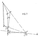
Il est possible de concevoir d'autres cas où ils ne seraient plus parallèles, tel que cela est représenté par exemple sur la figure 7, mais néanmoins la convergence initiale de AB et DC en F devrait être conservée.It is possible to conceive of other cases where they would no longer be parallel, as shown for example in FIG. 7, but nevertheless the initial convergence of AB and DC in F should be preserved.
Bien entendu, la droite de visée F - S Z reste dans tous les cas initialement perpendiculaire à la droite BC, c'est-à-dire E= θ0° .Of course, the line of sight F - S Z remains in all cases initially perpendicular to the line BC, that is to say E = θ0 °.
Le déplacement du foyer F en F' découle de lois géométriques classiques qui ne seront pas exposées ici.The displacement of the focal point F in F 'follows from conventional geometric laws which will not be explained here.
Seul, peut être pris en considération le fait que ce déplacement résulte d'un terme du second ordre qui reste toujours dans les limites acceptables dans la pratique. Ainsi, on peut atteindre, avec un choix convenable de paramètres, une défocalisation < 1 mm pour un angle avoisinant 1°, ce qui est convenable sur une antenne de satellite de radiodiffusion.Only can be taken into account the fact that this displacement results from a second order term which always remains within the limits acceptable in practice. Thus, one can achieve, with a suitable choice of parameters, a defocusing <1 mm for an angle of around 1 °, which is suitable on a broadcasting satellite antenna.
Il doit être noté qu'une légère anomalie de convergence de AB et CD en avant ou en arrière de F-S n'est pas rédhibitoire en regard de l'application du procédé selon l'invention, seule la recherche de la minimisation de la défocalisation F - F' doit guider le choix de l'adaptation des paramètres.It should be noted that a slight convergence anomaly of AB and CD in front or behind FS is not prohibitive with regard to the application of the method according to the invention, only the search for the minimization of defocus F - F 'must guide the choice of the adaptation of the parameters.
Dans cet esprit, il pourrait, de même, être envisagé, pour des applications particulières, un choix différent de point de convergence pour une plate-forme par rapport à l'autre.In this spirit, it could likewise be envisaged, for particular applications, a different choice of point of convergence for one platform compared to the other.
En revenant à la figure 4, on voit que les plates-formes 18 et 19 sont déplacées orthogonalement à l'aide de dispositifs électromagnétiques asservis à un détecteur de dépointage, ce qui autorise une grande raideur en torsion de l'ensemble.Returning to FIG. 4, it can be seen that the
Ces dispositifs électromagnétiques peuvent être du genre tel que ceux décrits dans la demande de brevet EP-A-0015829 précitée, repérés 16-17 sur la figure 4 et représentés à plus grande échelle sur la figure 8 et pour lesquels le principe de fonctionnement est rappelé ci-après.These electromagnetic devices can be of the type such as those described in the aforementioned patent application EP-A-0015829, identified 16-17 in FIG. 4 and shown on a larger scale in FIG. 8 and for which the operating principle is recalled below.
Chaque plate-forme 18 ou 19 porte donc un bobinage plat situé dans son plan et dont les brins sont dans le sens du déplacement. Ces bobinages 21 et 22 sont connectés à un boîtier d'asservissement 23 relié à un détecteur de dépointage 7 (non représenté).Each
Les commandes d'ordre étant ainsi découplées, chaque bobinage voit le sens de circulation du courant s'établir selon, par exemple, les flèches de la figure 8.The order commands being thus decoupled, each winding sees the direction of current flow established according to, for example, the arrows in FIG. 8.
Chaque bobinage est chevauché par un couple d'aimants 24-25, de polarité inversée, qui sont assujettis à la base fixe 12 par un support 26. La disposition des aimants et des bobines peut être inversée sans changer le résultat.Each coil is overlapped by a pair of magnets 24-25, of reverse polarity, which are fixed to the fixed
Selon le sens de circulation du courant et de son intensité, chaque plate-forme 18 ou 19 va donc se déplacer dans le champ magnétique dans le sens des flèches f1 ou f2 avec plus ou moins d'amplitude et ce conformément à la loi de LAPLACE.Depending on the direction of current flow and its intensity, each
De la sorte, du sens et de la valeur du courant envoyé sur chaque bobine vont dépendre le sens et la grandeur du déplacement de chaque plate-forme.In this way, the direction and the value of the current sent to each coil will depend on the direction and the magnitude of the displacement of each platform.
Bien entendu, la translation des plates-formes ne s'exerçant pas rigoureusement dans un plan, il importe de prévoir un espace de débattement (flèches e1, e2, e3, e4) pour chaque plate-forme.Of course, the translation of the platforms not being rigorously exercised in a plane, it is important to provide a clearance space (arrows e1, e2, e3, e4) for each platform.
Il est bien entendu possible de prévoir deux dispositifs par plate-forme sans que le principe ne s'en trouve modifié pour autant, chacun desdits dispositifs étant électriquement couplé en parallèle sur la boîte 23 (ou en redondance).It is of course possible to provide two devices per platform without the principle being thereby modified, each of said devices being electrically coupled in parallel on the box 23 (or in redundancy).
Il est de même à noter que pour les paraboloïdes utilisés dans le domaine électromagnétique des micro-ondes, la source d'émission et/ou de réception est, selon la manière connue, un cornet en guide d'ondes 8 à section progressivement croissante, solidaire de la base fixe.It should also be noted that for the paraboloids used in the electromagnetic field of microwaves, the source of emission and / or reception is, according to the known manner, a horn in waveguide 8 with progressively increasing section, secured to the fixed base.
Le paraboloïde constitue le réflecteur d'une antenne parabolique qui peut être mise en oeuvre, à travers l'invention, dans tous les domaines où elle est habituellement utilisée dès l'instant où la source S n'est pas assujettie à la directrice passant par le foyer F.The paraboloid constitutes the reflector of a parabolic antenna which can be implemented, through the invention, in all the fields where it is usually used from the moment when the source S is not subject to the director passing through foyer F.
Ainsi, l'application donnée pour un satellite de radiodiffusion n'est pas un cas restrictif de l'application du procédé conforme à l'invention mais il n'en constitue au contraire qu'un simple exemple.Thus, the application given for a broadcasting satellite is not a restrictive case of the application of the method according to the invention, but on the contrary is only a simple example.
Dans cet esprit, toutes les adaptations qui seraient faites de l'invention resteraient dans son cadre, lequel est défini dans les revendications qui suivent.In this spirit, all the adaptations which would be made of the invention would remain within its scope, which is defined in the claims which follow.
Claims (8)
Priority Applications (1)
| Application Number | Priority Date | Filing Date | Title |
|---|---|---|---|
| AT80401778T ATE5285T1 (en) | 1979-12-18 | 1980-12-11 | METHOD FOR CORRECTING CROSS FOCUS OF A DISH AND DEVICE FOR CORRECTING A DISH. |
Applications Claiming Priority (2)
| Application Number | Priority Date | Filing Date | Title |
|---|---|---|---|
| FR7930957A FR2472284A1 (en) | 1979-12-18 | 1979-12-18 | METHOD FOR CORRECTING THE TRANSVERSE DEFOCATION OF A PARABOLOID AND CORRESPONDING DEVICE FOR CORRECTING A PARABOLIC ANTENNA |
| FR7930957 | 1979-12-18 |
Publications (2)
| Publication Number | Publication Date |
|---|---|
| EP0030895A1 EP0030895A1 (en) | 1981-06-24 |
| EP0030895B1 true EP0030895B1 (en) | 1983-11-09 |
Family
ID=9232882
Family Applications (1)
| Application Number | Title | Priority Date | Filing Date |
|---|---|---|---|
| EP80401778A Expired EP0030895B1 (en) | 1979-12-18 | 1980-12-11 | Method of correcting the cross-defocusing of a paraboloid and matching device for correcting a parabolic antenna |
Country Status (7)
| Country | Link |
|---|---|
| US (1) | US4365252A (en) |
| EP (1) | EP0030895B1 (en) |
| JP (1) | JPS5694805A (en) |
| AT (1) | ATE5285T1 (en) |
| CA (1) | CA1156754A (en) |
| DE (1) | DE3065561D1 (en) |
| FR (1) | FR2472284A1 (en) |
Families Citing this family (5)
| Publication number | Priority date | Publication date | Assignee | Title |
|---|---|---|---|---|
| FR2502404A1 (en) * | 1981-03-20 | 1982-09-24 | Matra | Articulated mounting for satellite sub-assembly - uses output from inertial detector to control step or torque motor to move support arm for stabilisation |
| FR2523375A1 (en) * | 1982-03-10 | 1983-09-16 | Europ Agence Spatiale | REFLECTOR DISTORTION COMPENSATION DEVICE FOR MULTI-BEAM WAVES RECEIVING AND / OR TRANSMITTING ANTENNAS |
| FR2543697B1 (en) * | 1983-03-30 | 1985-08-23 | Aerospatiale | METHOD AND DEVICE FOR SUSPENSION AND DRIVE OF AN OSCILLATING SPATIAL TELESCOPE MIRROR |
| DE9014875U1 (en) * | 1990-10-27 | 1991-01-10 | Kabelmetal Electro Gmbh, 3000 Hannover, De | |
| US7118658B2 (en) * | 2002-05-21 | 2006-10-10 | Semitool, Inc. | Electroplating reactor |
Citations (1)
| Publication number | Priority date | Publication date | Assignee | Title |
|---|---|---|---|---|
| EP0015829A1 (en) * | 1979-02-28 | 1980-09-17 | AEROSPATIALE Société Nationale Industrielle | Electromagnetic process for controlling the orientation of a platform and platform employing this process |
Family Cites Families (7)
| Publication number | Priority date | Publication date | Assignee | Title |
|---|---|---|---|---|
| GB905440A (en) * | 1957-12-18 | 1962-09-05 | Gen Electric Co Ltd | Improvements in or relating to position control arrangements and aerial systems including such arrangements |
| US3166750A (en) * | 1961-02-14 | 1965-01-19 | Raytheon Co | Antenna intersecting-orthogonal-axes gimbal mount utilizing rotary bearings for two axes and push-pull linkage for third axis |
| US3262321A (en) * | 1963-09-16 | 1966-07-26 | Jr George E Moul | Two-rod seeker head |
| DE1273625B (en) * | 1964-04-03 | 1968-07-25 | Boelkow Gmbh | News satellite with a radio relay system and with a configuration in the form of a dumbbell |
| US3374977A (en) * | 1966-06-09 | 1968-03-26 | Collins Radio Co | Antenna positioner |
| US3565515A (en) * | 1967-12-12 | 1971-02-23 | Perkin Elmer Corp | Mounts for optical elements |
| JPS5028148B1 (en) * | 1969-11-28 | 1975-09-12 |
-
1979
- 1979-12-18 FR FR7930957A patent/FR2472284A1/en active Granted
-
1980
- 1980-12-02 CA CA000365921A patent/CA1156754A/en not_active Expired
- 1980-12-03 US US06/212,663 patent/US4365252A/en not_active Expired - Lifetime
- 1980-12-11 EP EP80401778A patent/EP0030895B1/en not_active Expired
- 1980-12-11 AT AT80401778T patent/ATE5285T1/en active
- 1980-12-11 DE DE8080401778T patent/DE3065561D1/en not_active Expired
- 1980-12-16 JP JP17796380A patent/JPS5694805A/en active Granted
Patent Citations (1)
| Publication number | Priority date | Publication date | Assignee | Title |
|---|---|---|---|---|
| EP0015829A1 (en) * | 1979-02-28 | 1980-09-17 | AEROSPATIALE Société Nationale Industrielle | Electromagnetic process for controlling the orientation of a platform and platform employing this process |
Also Published As
| Publication number | Publication date |
|---|---|
| JPS5694805A (en) | 1981-07-31 |
| EP0030895A1 (en) | 1981-06-24 |
| FR2472284B1 (en) | 1981-12-24 |
| CA1156754A (en) | 1983-11-08 |
| DE3065561D1 (en) | 1983-12-15 |
| FR2472284A1 (en) | 1981-06-26 |
| ATE5285T1 (en) | 1983-11-15 |
| US4365252A (en) | 1982-12-21 |
| JPH0136282B2 (en) | 1989-07-31 |
Similar Documents
| Publication | Publication Date | Title |
|---|---|---|
| EP2270922B1 (en) | Antenna with mission flexibility, satellite comprising such an antenna and method for controlling mission changes in such an antenna | |
| EP0656671B1 (en) | Orientable antenna with maintenance of the polarisations axes | |
| EP0030895B1 (en) | Method of correcting the cross-defocusing of a paraboloid and matching device for correcting a parabolic antenna | |
| EP1188668B1 (en) | Orientation device and on-board orientation system | |
| FR2531817A1 (en) | ANTENNA STRUCTURE | |
| FR2598339A1 (en) | PARABOLIC REFLECTOR ANTENNAS AND METHOD FOR OBTAINING THE SAME | |
| FR2825478A1 (en) | ELECTROMAGNETIC WAVE FOCUSING DEVICE | |
| EP3457489B1 (en) | Rotary joint for a rotating antenna and rotating antenna comprising such a joint | |
| EP0548876B1 (en) | An active offset antenna having two reflectors | |
| US6342865B1 (en) | Side-fed offset cassegrain antenna with main reflector gimbal | |
| EP3457490B1 (en) | Biaxial antenna comprising a first fixed portion, a second rotary portion and a rotating joint | |
| FR2646023A1 (en) | Antenna pointing device, satellite equipped with such a device and antenna pointing process using such a device | |
| EP0032081B1 (en) | Directable-beam antenna for communication satellite | |
| EP3675278B1 (en) | Multibeam antenna with adjustable pointing | |
| EP0072316A1 (en) | Electronic scanning antenna with multiple ports and radar using such antenna | |
| FR2760900A1 (en) | ANTENNA FOR SCROLL SATELLITE | |
| FR2578058A1 (en) | METHOD AND DEVICE FOR PURSUING A COMMUNICATION SATELLITE | |
| EP4025502B1 (en) | Method for producing a satellite from a generic configuration of antenna elements | |
| FR2535479A1 (en) | Orientation device without solid friction, and application to a space vehicle. | |
| FR2593646A1 (en) | RADAR ANTENNA WITH LOW DIMENSIONS. | |
| EP0229617A1 (en) | Antenna-orientating device for scanning in two orthogonal directions | |
| EP3220181B1 (en) | Hybrid optical system with reduced size for imaging array antenna | |
| EP1950523B1 (en) | System of nozzles for controlling the trajectory of a moving body | |
| FR2581615A1 (en) | SATELLITE TELECOMMUNICATIONS GEOSTATIONNAIRE | |
| FR2690532A1 (en) | Pointing, or aiming, device for optical equipment e.g. for satellite communication using modulated laser beam - has system of two mirrors rotating about axes perpendicular to each other with fine tuning of first mirror |
Legal Events
| Date | Code | Title | Description |
|---|---|---|---|
| PUAI | Public reference made under article 153(3) epc to a published international application that has entered the european phase |
Free format text: ORIGINAL CODE: 0009012 |
|
| AK | Designated contracting states |
Designated state(s): AT BE CH DE GB IT NL SE |
|
| 17P | Request for examination filed |
Effective date: 19810711 |
|
| ITF | It: translation for a ep patent filed |
Owner name: BARZANO' E ZANARDO ROMA S.P.A. |
|
| GRAA | (expected) grant |
Free format text: ORIGINAL CODE: 0009210 |
|
| AK | Designated contracting states |
Designated state(s): AT BE CH DE GB IT LI NL SE |
|
| REF | Corresponds to: |
Ref document number: 5285 Country of ref document: AT Date of ref document: 19831115 Kind code of ref document: T |
|
| REF | Corresponds to: |
Ref document number: 3065561 Country of ref document: DE Date of ref document: 19831215 |
|
| PLBE | No opposition filed within time limit |
Free format text: ORIGINAL CODE: 0009261 |
|
| STAA | Information on the status of an ep patent application or granted ep patent |
Free format text: STATUS: NO OPPOSITION FILED WITHIN TIME LIMIT |
|
| 26N | No opposition filed | ||
| ITTA | It: last paid annual fee | ||
| PGFP | Annual fee paid to national office [announced via postgrant information from national office to epo] |
Ref country code: GB Payment date: 19941130 Year of fee payment: 15 |
|
| PGFP | Annual fee paid to national office [announced via postgrant information from national office to epo] |
Ref country code: SE Payment date: 19941216 Year of fee payment: 15 |
|
| PGFP | Annual fee paid to national office [announced via postgrant information from national office to epo] |
Ref country code: CH Payment date: 19941219 Year of fee payment: 15 |
|
| PGFP | Annual fee paid to national office [announced via postgrant information from national office to epo] |
Ref country code: AT Payment date: 19941230 Year of fee payment: 15 |
|
| PGFP | Annual fee paid to national office [announced via postgrant information from national office to epo] |
Ref country code: NL Payment date: 19941231 Year of fee payment: 15 |
|
| PGFP | Annual fee paid to national office [announced via postgrant information from national office to epo] |
Ref country code: BE Payment date: 19950110 Year of fee payment: 15 |
|
| EAL | Se: european patent in force in sweden |
Ref document number: 80401778.8 |
|
| PGFP | Annual fee paid to national office [announced via postgrant information from national office to epo] |
Ref country code: DE Payment date: 19950131 Year of fee payment: 15 |
|
| PG25 | Lapsed in a contracting state [announced via postgrant information from national office to epo] |
Ref country code: GB Effective date: 19951211 Ref country code: AT Effective date: 19951211 |
|
| PG25 | Lapsed in a contracting state [announced via postgrant information from national office to epo] |
Ref country code: SE Effective date: 19951212 |
|
| PG25 | Lapsed in a contracting state [announced via postgrant information from national office to epo] |
Ref country code: LI Effective date: 19951231 Ref country code: CH Effective date: 19951231 Ref country code: BE Effective date: 19951231 |
|
| BERE | Be: lapsed |
Owner name: SOC. NATIONALE INDUSTRIELLE AEROSPATIALE Effective date: 19951231 |
|
| PG25 | Lapsed in a contracting state [announced via postgrant information from national office to epo] |
Ref country code: NL Effective date: 19960701 |
|
| GBPC | Gb: european patent ceased through non-payment of renewal fee |
Effective date: 19951211 |
|
| REG | Reference to a national code |
Ref country code: CH Ref legal event code: PL |
|
| NLV4 | Nl: lapsed or anulled due to non-payment of the annual fee |
Effective date: 19960701 |
|
| PG25 | Lapsed in a contracting state [announced via postgrant information from national office to epo] |
Ref country code: DE Effective date: 19960903 |