EP0030242B1 - Stackable chair - Google Patents
Stackable chair Download PDFInfo
- Publication number
- EP0030242B1 EP0030242B1 EP80901298A EP80901298A EP0030242B1 EP 0030242 B1 EP0030242 B1 EP 0030242B1 EP 80901298 A EP80901298 A EP 80901298A EP 80901298 A EP80901298 A EP 80901298A EP 0030242 B1 EP0030242 B1 EP 0030242B1
- Authority
- EP
- European Patent Office
- Prior art keywords
- frame
- horizontal
- chair
- vertical
- seat
- Prior art date
- Legal status (The legal status is an assumption and is not a legal conclusion. Google has not performed a legal analysis and makes no representation as to the accuracy of the status listed.)
- Expired
Links
Images




Classifications
-
- A—HUMAN NECESSITIES
- A47—FURNITURE; DOMESTIC ARTICLES OR APPLIANCES; COFFEE MILLS; SPICE MILLS; SUCTION CLEANERS IN GENERAL
- A47C—CHAIRS; SOFAS; BEDS
- A47C3/00—Chairs characterised by structural features; Chairs or stools with rotatable or vertically-adjustable seats
- A47C3/04—Stackable chairs or nesting chairs
Definitions
- This invention relates to a stacking chair and to a frame therefor.
- the invention relates to a frame for a stacking chair, including in combination a main frame element having a U-shaped, horizontal portion from which extends a pair of vertical front legs, said U-shaped portion having a rear, horizontal lateral stretcher portion joined at each end by a curved corner to a horizontal side portion each of which side portions is joined to a respective said front leg, said front legs being substantially parallel to each other, and frame means for providing a pair of rear legs each having an upwardly extending back-support portion, said rear legs being joined to said main frame element, and being held at a distance apart greater than the distance between the outermost portions of said side portions, and to a standing chair incorporating such a frame.
- stacking chairs have usually been so designed that when nested in a stack there was considerable vertical space between them, often several centimetres. As a result, only a few chairs could be put into one stack; moreover, stacking them and removing them from the stack was difficult. Compact stacking has been rare; although it has been achieved with special structures.
- stacking chairs were especially heavy because they required such extra frame members.
- Stacking chairs made of steel tubing heretofore required either a stiff frame member or stiff shelf portion across the top of the back and another stiff frame member or stiff shelf shelf portion across the front of the seat.
- the seat and the back had to be so rigid that they would provide the needed strength. The more rigid the seat or back was, the less comfortable it was.
- stacking chairs when stacked, have usually resulted in the frame of one coming against the frame of the other. Often this has done so in a manner such as to scratch the frames or to scrape off their finish. If they were spaced apart vertically so as to protect the finish so much space was left that the stack could not be compact, as remarked earlier.
- the present invention seeks to reduce or obviate these disadvantages.
- a frame for a stacking chair including in combination a main frame element having a U-shaped, horizontal portion from which extends a pair of vertical front legs, said U-shaped portion having a rear, horizontal lateral stretcher portion joined at each end by a curve corner to a horizontal side portion each of which side portions is joined to a respective said front leg, said front legs being substantially parallel to each other, and frame means for providing a pair of rear legs each having an upwardly extending back-support portion, said rear legs being joined to said main frame element and being held at a distance apart greater than the distance between the outermost portions, of said side portions wherein curved corners join each horizontal side portion to a respective front leg, and wherein the said side portions are generally parallel to each other, but diverge somewhat from rear to front, and wherein a pair of frame-juncture-and-spacing members are provided each constituted by a plate-like member formed to have a substantially horizontal portion with a pair of opposite substantially horizontal edges and a substantially vertical portion having
- each of frame-juncture-and-spacing member is secured to the main frame element over the entire length of the edge, the length of said horizontal edge being greater than the thickness of the frame element, and the said vertical edge of each frame-juncture-and-spacing-member may be secured to the frame means providing the rear legs over the entire length of the edge, the length of said vertical edge being substantially greater than the thickness of each of the rear legs so that the vertical edge and the horizontal edge secured to the main frame element extend well beyond the crossover area between the frame means and the main frame element.
- each said frame-juncture - and - spacing member has a generally horizontal top wall portion with a pair of opposite generally horizontal edges and a pair of opposite generally vertical wall portions extending down between said horizontal edges, each said vertical portion having a pair of generally vertical edges, each continuous with a said horizontal edge, one said horizontal edge and two adjacent said vertical edges of each frame-juncture - and - spacing - member being shaped to fit and being secured to the side of said main frame element adjacent to one of the corners at each end of said lateral portion and extending laterally beyond said side portions, the other said horizontal edge and the adjacent two vertical edges being shaped to fit and being secured to a said rear leg.
- said main frame element and said rear legs are tubular metal and said frame-juncture - and - spacing member is metal and of a thickness substantially the same as the wall thickness of said tubular metal and has a shorter arcuate horizontal edge for welding to said rear leg and a wider horizontal edge for welding to said main frame element, the generally horizontal top wall portion being substantially wider than the diameter of the tubular metal frame and said generally vertical walls being higher than the diameter of said tubular metal frame.
- the welds are below said generally horizontal top wall portions and extend continuously along the lower edge thereof and continuously along the inside edges of said generally vertical side wall portions, so that the welds are generally hidden from view.
- the frame-juncture-and-spacing-members may each comprise a single vertical portion which is formed at its lower end into said horizontal portion.
- the frame means may comprises two completely separate rear leg members, the back-supporting portions thereof diverging somewhat upwardly. Also said frame means may comprise a top bar joining together the back-support portions, of said rear legs.
- said frame-juncture-and-spacing means is the only means connecting the separate frame elements to each other and said lateral stretcher portion is the only rigid member rigidly connected to said side portions.
- each said side portion is provided with means for assuring accurate vertical alignment of a chair frame to be stacked thereabove, and for spacing such a stacked chair frame so as to provide scratch protection for itself.
- the frame has tubular legs, and a bottom glide for each leg comprising a plastic member with a shank portion inserted inside the tubular leg and an enlarged outer portion of the same diameter as the leg.
- the invention also relates to a stacking chair comprising a frame generally as described above wherein said back-support portions are generally parallel to each other but diverge somewhat upwardly, there being a seat bridging and secured to said two side portions and urging them toward a truly parallel relationship, and a back bridging and secured to said two back-support portions and urging them toward a truly parallel relationship.
- said seat and said back are non-rigid and resilient with opposite ends of each connected rigidly to said two side portions and two back-support portions respectively.
- said seat said back are cloth fabric with ends thereof looped around and stitched together at each said side portion and each said back-support portion under sufficient tension to prevent sagging.
- said seat said back are cloth fabric having stitched loops at each end, there being a linear member in each said loop and a hook-like channel on each of said side portions and back-support portions engaging and holding the cloth-enclosed linear members.
- said seat and back are rigid members, and means are provided for connecting them to said chair frame in a non-rigid manner for holding them in place, and for enabling flexure of said frame portions distant from said juncture and spacing members.
- the said seat and back may be metal and may have hooked channel ends, said frame having hooked strips secured thereto and interlocking with said hooked channel ends.
- said seat and back are plywood, said frame having strips secured rigidly thereto and bolted or secured to said seat and back with resilient yieldable means interspaced between said strips and said seat and said back.
- the invention comprises a stackable chair and a frame for such a chair, in which the frame includes a main frame element comprising a U-shaped horizontal portion and a pair of vertical front legs.
- the U-shaped portion has a rear, horizontal cross or lateral portion, joined at each end by a corner to a horizontal side portion, each of which is respectively joined by a corner to a front leg.
- the front legs are substantially parallel to each other, and the side portions are generally parallel to each other but diverge slightly from rear to front.
- the frame also includes a pair of rear legs, each with a back-support portion in line with the rear leg but preferably curving slightly rearwardly.
- the back-support portions are generally parallel to each other, but when they are part of two separate members, they preferably diverge slightly as one moves upwardly.
- the frame members are secured together by a pair of cupped frame-juncture-and-spacing members, each of which is shaped as a generally triangular-looking cup with a horizontal top and a pair of vertical depending sides.
- the top has a pair of horizontal edges and each vertical side has a pair of vertical edges at each end.
- a wider horizontal edge and two of the vertical edges are welded to the sides of the main frame element adjacent to the corners by which the cross member merges into the side members, thereby providing sideways spacing.
- the other horizontal edge and two vertical edges are each welded to a rear leg. This places the rear legs and back-support portions outside the front legs, so that they are sufficiently farther apart from each other than are the front legs, thereby making the chair stackable.
- a seat preferably non-rigid and resilient, bridges and is secured to the two side portions of the frame and urges them toward a truly parallel relationship
- a back also preferably non-rigid and resilient, bridges and is secured to the two back-support portions and urges them toward a truly parallel relationship.
- These seat and back portions may be made from the materials shown in U.S. Patents numbers 3,720,568 and 3,843,477. When that material is used (usually sold under the Registered Trade Mark SOFLEX) then an especially comfortable and resilient seat is obtained.
- the seat or back may be covered or encased in additional fabric. In place of this preferred seating material, ordinary fabric may be used when properly designed. Alternatively, wood, metal, plastic, and other rigid seats and backs may be used.
- each frame side portion may be provided with two plastic members secured to or projecting from a lower surface of the side portions, one preferably near the front and the other preferably near the rear. One of these faces inwardly and the other faces outwardly, to provide a kind of locking engagement, effective to space the successive chairs slightly apart so that they rest on these non-scratching plastic members but still compactly stacked.
- the frame elements are preferably metal and all may be made of the same tubular stock, if desired.
- a bottom glide may be inserted into the tube and may comprise a plastic member with an outer portion substantially the same diameter as that of the leg.
- FIGS. 5 and 6 show that the frame 51 of the described embodiment of this invention is adapted to many different kinds of seat and back arrangements. As will be seen later, however, it is more desirable to have the seat and back of non-rigid material than it is to have them of rigid material.
- the seats 52 and 56 and the backs 53 and 57 are especially comfortable and are highly recommended whether as shown in Figures 1 to 3 or whether incorporated in a fabric case so that they would appear as in Figures 5 and 6.
- the use of simple fabric seats is also feasible, as is the use of wood, plastic, or metal seats.
- FIG. 7 is an exploded view of the frame assembly 51 and shows all the elements of that frame.
- the frame assembly 51 includes as principal components a main frame element 60, two other frame elements 61 and 62 which comprise the rear legs and frame-juncture-and-spacing members 63 and 64.
- the main frame member 60 has a horizontal U-shaped portion from which the front legs depend. Thus, it has a rear horizontal cross, lateral, or stretcher member 65 joined to side rail portions 66 and 67 by rounded corners 68 and 69; and these side members 66 and 67 are joined at their forward end to two front legs 70 and 71 by rounded corners 72 and 73.
- the entire main frame member 60 may be made from a single piece of metal tubing bent to shape.
- the two rear legs members 61 and 62 are preferably identical, each of them having an upper back-supporting portion 74 and 75, each preferably having a rearwardly inclined portion 76 or 77.
- the frame-juncture-and-spacing members 63 and 64 are illustrated in enlarged form in Figures 10 to 19, 23 and 24. They are symmetric to each other and, when attached, are cup-like in shape and, from above appear somewhat trapezoidal. Thus, it has a generally trapezoidal, substantially flat, upper horizontal wall portion 80 from which depend vertical side walls 81 and 82, via downwardly curving corners. At the opposite ends of the upper wall 80 are a long, mostly curved horizontal edge 83 and a shorter semicircular horizontal edge 84.
- the edge 84 has a radius to fit its leg member 61 or 62 and is welded thereto.
- the edge 83 is curved to match the curve 68 or 69 where it abuts it.
- the vertical side walls 81, 82 have vertical edges 85, 86, 87 and 88.
- the edge 83 and the edges 85 and 87 form a continuous edge which is welded by any suitable welding technique to the main frame member 60.
- the location is important, and the juncture and spacing members 63 and 64 are continuously shaped to fit the frame member 60 at an exact spot, near and along part of the corners 68 and 69 and including a portion thereof, but also partly along the rear end of the side members 66 and 67 so that the juncture and spacing members 63 and 64 will act to space the rear legs 61 and 62 out laterally from the frame 60.
- edges 86 and 88 may be straight, to abut the rear leg 61 or 62, but the edges 85 and 87 are curved to match the contour of the side rail 66 or 67 and other portions of the frame 60 are to abut, as shown at 89 and 90.
- the securing to the rear legs 61 and 62 is done along the edges 84, 86 and 88, which also lie as a continuous edge, and again, welding is used.
- the juncture and spacing members 63 and 64 and the welding provide the sole rigid connections between the shaped frame members.
- the two juncture and spacing members 63 and 64 rigidly connect the rear legs 61 and 62 to the frame member 60 at a point near the back thereof and space the rear legs 61 and 62 out laterally sufficiently so that the chair 50 or 55 can stack.
- the legs 61 and 62 are therefore farther apart than the legs 70 and 71 at the front, at least by the thickness of the frame members.
- all of the joining edges 83, 84, 85, 86, 87 and 88 are welded throughout their full length to the frame tubes 61 and 66, 68 or 62 and 67, 69. The welding is all done from below and inside the box-like configuration, so that the whole gives a clean appearance, eliminating the need for finishing off the welds, shown at 79.
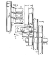
- Figures 15 and 16 show some interesting features relating to the juncture and spacing members 63 and 64.
- the vertical extent of the contact between the juncture and spacing member 63 or 64 and the rear leg 61 or 62 (along the edges 84, 86 and 88) is shown at H 1 and is preferably greater than the diameter H 2 of the seat frame tubing.
- the horizontal extent 0 1 of contact between the juncture and spacing member 63 or 64 and the seat frame 60 should be preferably be greater than the diameter D 2 of the seat frame tubing.
- D 2 H 2
- the thickness of the metal juncture and spacing members 63 and 64 is the same as that of the members 60, 61, and 62, to assure evenness in temperature during welding.
- the spacing must be sufficient to achieve the difference between the distance between the rear legs and that of the front legs needed for stacking.
- the juncture and spacing members 63 and 64 are so shaped and located that they do not interfere with the compact stacking and do not engage their corresponding parts on other chairs when the chairs are stacked.
- Figures 32 and 34 illustrate the side portions 66 and 67 preferably diverge from each other to rear and front so that the distance between the front legs 70 and 71 is preferably at least 5% greater than the distance there would be between them if they were truly parallel and to which they are usually held by the seat 52 or 56.
- the upper ends of the back portions 74 and 75 preferably diverge from the juncture and spacing members 63 and 64 so that the distance between them is preferably at least 5% greater than the distance to which they are brought by the back 53 or 57 in the preferable constructions. This enables spreading and, as it will be seen later, the same absence from rigidity has advantages in enabling the user to sit comfortably on an uneven surface.
- the chair 55 will adjust itself so that it will not feel tippy or unstable even though the bottoms of the legs are at different levels.
- the height H of the block 100 shown in Figure 21, which is made to scale, can be as much as one centimeter (ten millimeters).
- Figure 22 shows that the same thing applies just as well for a rear leg 62 being the one where the rise in the ground surface is.
- Figures 8 and 9 show that the chairs 50 or 55 can be made very compactly stackable.
- the actual stack height per chair depends on the thickness of the frame members and on the spacing between them, which is kept quite close.
- the seat 52 or 56 and back 53 or 57 are made thinner than the frame 51 and do not enter into consideration for compactness of stacking.
- the stacked chairs in large groups are preferably supported on a dolly 91 having an inclined portion 92 and inclined back 93 for supporting both the front and rear legs of the bottom chair and a portion of the rear legs leading up at the back.
- the subsequent stack is then supported by the dolly 80 which, having wheels 94, can be moved from place to place.
- the stacking calls for a buffering or spacing of the successive frames 51 from each other by a small amount in order to prevent the frames 51 from scratching each other during stacking and unstacking.
- a pair of plastic separators 95 and 96 are used on each side frame member 66, 67.
- the separators 95 and 96 are preferably identical, and they may be in the form of hole plugs secured to the main frame member 51.
- they are located on the side members 66 and 67, one being located near the front thereof and the other near the rear, as shown in Figure 3.
- a hole 97 is drilled through the side member 66 or 67 to take each separating member 95, 96.
- the members 95 and 96 are preferably made of plastic, and each has a rounded head 98 and a generally conical step 99 with a pair of flexible fins 102 that hold the stem 99 in place once it is inserted through the opening 97.
- the fins 102 tend to fold to permit entry of the stem 99 into the opening 97, but once through the opening 97, the fins 102 are difficult to retract. Only the heads 98 project from the openings 97, and they are held in place by the stem 99 and fins 102 so that they are held very close to the frame member, projecting only a sufficient amount to prevent the frames 51 from touching each other.
- the distance D 3 shown in Figure 26 is the distance between the point where the separator 95 bears against the chair frame member 67A below it and the actual top of that frame, while the distance D 4 is the spacing between the two frame members 67 and 67A as a result of this expedient. Therefore, as can be seen from Figures 23 to 25 (as well as in Figures 8 and 9), the stacking can be compact while direct frame contact is avoided.
- the spacing S is also shown in Figures 16 and 17.
- Suitable glides 103 may be used to support the chair, and if the stock from which the chairs are made is tubular, then the glides 103 may be as shown in Figure 7, each having a stem portion 104 that is inserted up into each leg and fits snugly in the interior of the leg, and also having an exterior portion 105 which has preferably substantially the same diameter as the chair legs 61, 62, 70 and 71. This helps to make a very trim-looking chair.
- the chair frame 51 as shown in Figures 2 and 7 is preferably provided with a pair of seat- securing members 106 and 107 and a pair of back-securing members 108 and 109.
- These members 106, 107, 108 and 109 are clip-strips welded onto the side frames 66 and 67 for the seat and to the back members 74 and 75 for the back and have projections 110 that enable a rapid and secure affixation of the seat 52 or 56 and the back 53 or 57. Hooks on the end of the seat 52 or 56 and back 53 or 57 engage the projections 110, which then hold them in place. The projections 110 may then be crimped around the end hooks.
- a free-floating stretcher rod 112 may be used to prevent any tendency of the chair 50 to collapse with soft upholstery.
- two openings 113 and 114 are drilled into the inside wall of the respective side members 66 and 67, and the rod 112, significantly smaller in diameter than either of these openings 113 and 114, is inserted to bridge the distance between the side members 66 and 67 and to extend into the frame to a position where it is capable of bearing against the opposite wall thereof.
- the rod 112 prevents any tendency for the chair to be collapsed inwardly by abusive compressive forces; at the same time, since the connection is not rigid, it also perpetuates the frame's flexibility when the chair is being sat upon and enables the desired vertical movement for a type of knee action that enables the chair to adjust to uneven base surfaces, as just described above, the same dimension H shown in Figures 20 to 22 being shown in Figure 30.
- FIG 31 illustrates a further chair 120 in accordance with the invention.
- the two rear leg back-support members of this chair may actually be part of a single unitary tubular steel member 121 bent to provide two rear legs 122 and 123, back-support portions 124 and 125, and also a rigid stretcher member 126 which extends across the back. This is somewhat less desirable, because it adds weight to the chair, but it does have the advantage of helping people who are used to handling chairs by members across the back to move them around from place to place.
- the frame members 66 and 67 when using a textile seat 140, may be provided with members 141 and 142, each shaped somewhat like a question mark with a long straight portion 143 welded to the frame member 66 or 67 and a hook portion 144 extending out therefrom. Then a seat 140 which is prestitched and has thin rods 145 slid into pre-made stitched loops 146 can be placed in the hook member 144 and held in place by the tendency of the frame members 66 and 67 to space apart.
- One of the most important features of the preferred embodiments of the invention is the ability of outboard frame portions to flex.
- the connecting and spacing members 63 and 64 the frame members are connected quite rigidly, but the outboard portions of the frame 51 (such as the front legs 70 and 71) and the upper back portion 76 and 77 can flex.
- Rigid seats and backs can be installed on the frame 51 in a rigid manner, but this foregoes some of the advantages of the preferred chair, nullifying most of its ability to flex, to adjust to uneven floors or terrain, and to adjust to sitters that shift their weight.
- Figures 39 to 41 show a sheet metal seat 150 provided at each end with a hook-shaped channel 151, 152.
- Matching hook-shaped channels 153, 154 are welded to the side rails 66 and 67 and interlock with the hook-shaped channels 151 and 152, preferably an elastic member 155, 156 (preferably extruded in the shape illustrated) lies between the members 151 and 153 and the members 152 and 154.
- the rigid seat 150 does not greatly affect the ability of the frame 51 to flex.
- Figures 42 and 43 show a moulded plywood seat 160 secured to a bracket 161 or 162 at each end by a screw 163 or 164, the brackets 161 and 162 being welded to the frame side rails 66 and 67.
- a block or disc 165, 166 of elastomer enables the desired flexing action, as shown.
- Figures 44 to 46 show a juncture and spacing member 170, in the form of a metal plate with a single bend 171.
- the plate thus constitutes two buttresses 172 and 173, the buttress 172 being generally vertical, while the buttress 173 is generally horizontal.
- the plate should preferably be at least twice the thickness of the tubing wall thickness.
- One edge 174 of the vertical buttress 174 is straight and is welded to the leg 62.
- the other edge 175 of the buttress 172 is curved and is welded to the frame members 67, 69, and 65, as shown.
- One edge 176 of the horizontal buttress 173 is arcuate and is welded to the leg 62.
- the opposite edge 177 of the horizontal buttress 173 is curved to follow the shape of the frame portion 69 and is welded to the frame member 60, as shown. These welds are not so completely hidden as with the members 63 and 64, but are located as unobviously as possible. Thus, the desired strong rigid connection and also the spacing are provided.
- the angled edge 178 of the buttress 173 enables the stacking of the frames without striking the buttress 173 against another chair frame.
- preferred embodiments of this invention provide a comfortable, compactly stackable chair; provide stacking chairs that do not need to incorporate a front, horizontal, rigid stretcher, especially one between the legs; provide a chair that is not completely rigid so that it can flex sufficiently to accommodate itself to an uneven floor; provide a stacking chair which can be relatively light in weight; provide a stacking chair in which the frame member is protected from scratching and from rubbing against the frame of an adjacent stretched chair and provide a chair that can utilize many kinds of seating material, including fabric seating, without developing the bagginess and sloppy appearance but in which slack is automatically taken up by the chair.
Landscapes
- Chairs Characterized By Structure (AREA)
- Fuel Cell (AREA)
- Stackable Containers (AREA)
- Pallets (AREA)
- Chairs For Special Purposes, Such As Reclining Chairs (AREA)
- Accommodation For Nursing Or Treatment Tables (AREA)
- Chair Legs, Seat Parts, And Backrests (AREA)
Priority Applications (1)
| Application Number | Priority Date | Filing Date | Title |
|---|---|---|---|
| AT80901298T ATE4772T1 (de) | 1979-06-08 | 1980-06-04 | Stapelbarer stuhl. |
Applications Claiming Priority (2)
| Application Number | Priority Date | Filing Date | Title |
|---|---|---|---|
| US06/046,836 US4304436A (en) | 1979-06-08 | 1979-06-08 | Stackable chair |
| US46836 | 1979-06-08 |
Publications (3)
| Publication Number | Publication Date |
|---|---|
| EP0030242A1 EP0030242A1 (en) | 1981-06-17 |
| EP0030242A4 EP0030242A4 (en) | 1981-10-13 |
| EP0030242B1 true EP0030242B1 (en) | 1983-09-28 |
Family
ID=21945656
Family Applications (1)
| Application Number | Title | Priority Date | Filing Date |
|---|---|---|---|
| EP80901298A Expired EP0030242B1 (en) | 1979-06-08 | 1980-12-30 | Stackable chair |
Country Status (10)
| Country | Link |
|---|---|
| US (1) | US4304436A (cg-RX-API-DMAC7.html) |
| EP (1) | EP0030242B1 (cg-RX-API-DMAC7.html) |
| JP (1) | JPS56500641A (cg-RX-API-DMAC7.html) |
| AT (1) | ATE4772T1 (cg-RX-API-DMAC7.html) |
| AU (1) | AU6059080A (cg-RX-API-DMAC7.html) |
| CA (1) | CA1141280A (cg-RX-API-DMAC7.html) |
| DE (1) | DE3065031D1 (cg-RX-API-DMAC7.html) |
| ES (2) | ES258046Y (cg-RX-API-DMAC7.html) |
| IT (1) | IT1147747B (cg-RX-API-DMAC7.html) |
| WO (1) | WO1980002790A1 (cg-RX-API-DMAC7.html) |
Families Citing this family (39)
| Publication number | Priority date | Publication date | Assignee | Title |
|---|---|---|---|---|
| US4366980A (en) * | 1979-06-08 | 1983-01-04 | Rowland David L | Stackable armchair |
| CH639836A5 (de) * | 1979-08-03 | 1983-12-15 | Intercollection Dev Sa | Sitzmoebel. |
| FR2517945B1 (fr) * | 1981-12-10 | 1985-05-31 | Lafa Tables Sieges | Perfectionnements aux chaises |
| DE3210525A1 (de) * | 1982-03-23 | 1983-10-06 | Bitsch Hans Ulrich | Sitzmoebel |
| US4621865A (en) * | 1984-08-14 | 1986-11-11 | Herrera Fernando Q | Demountable patio furniture |
| US5318346A (en) * | 1991-05-30 | 1994-06-07 | Steelcase Inc. | Chair with zero front rise control |
| US5630643A (en) * | 1993-06-01 | 1997-05-20 | Steelcase Inc | Upholstered chair with two-piece shell |
| USD498072S1 (en) | 1999-02-16 | 2004-11-09 | Shelby Williams Industries, Inc. | Stack seat with x back |
| USD420821S (en) * | 1999-02-16 | 2000-02-22 | Shelby Williams Industries, Inc. | Stacking bar stool with x back |
| USD433830S (en) * | 1999-02-16 | 2000-11-21 | Shelby Williams Industries, Inc. | Stacking bar stool with vertical back |
| USD431725S (en) * | 1999-02-16 | 2000-10-10 | Shelby Williams Industries, Inc. | Stack seat with vertical back |
| USD431385S (en) * | 1999-02-16 | 2000-10-03 | Shelby Williams Industries, Inc. | Stack seat with horizontal back |
| USD433829S (en) * | 1999-02-16 | 2000-11-21 | Shelby Williams Industries, Inc. | Stacking bar stool with horizontal back |
| US6540950B1 (en) * | 2000-09-20 | 2003-04-01 | Dahti, Inc. | Carrier and attachment method for load bearing fabric |
| US6842959B2 (en) | 2001-01-25 | 2005-01-18 | Dahti, Inc. | Load bearing fabric attachment and associated method |
| US7118175B2 (en) * | 2001-09-05 | 2006-10-10 | Vendor Development Group | Securely stacking bar stools |
| USD477926S1 (en) | 2002-05-29 | 2003-08-05 | Lifetime Products, Inc. | Chair |
| USD466712S1 (en) | 2002-07-17 | 2002-12-10 | Lifetime Products, Inc. | Chair |
| USD472745S1 (en) | 2002-07-23 | 2003-04-08 | Lifetime Products, Inc. | Chair back and seat |
| USD472723S1 (en) | 2002-07-23 | 2003-04-08 | Lifetime Products, Inc. | Chair frame |
| USD508339S1 (en) | 2003-05-16 | 2005-08-16 | Lifetime Products, Inc. | Chair |
| USD507425S1 (en) | 2004-05-11 | 2005-07-19 | Lifetime Products, Inc. | Chair |
| US9527519B1 (en) | 2004-06-08 | 2016-12-27 | Chameleon Chairs, Llc | Modular stackable furniture systems |
| US8454088B2 (en) | 2004-06-08 | 2013-06-04 | Chameleon Chairs LLC | Modular stackable furniture systems |
| US8047607B1 (en) * | 2004-06-08 | 2011-11-01 | Behshad Shokouhi | Modular stackable furniture systems |
| US7316452B2 (en) | 2005-03-29 | 2008-01-08 | Cushion Seats, Inc. | Stadium seat |
| US7404607B2 (en) * | 2006-01-04 | 2008-07-29 | Vendor Development Group | Easy assembly barstool |
| US20100066140A1 (en) * | 2008-09-15 | 2010-03-18 | Michigan Tube Swagers & Fabricators, Inc. | Stackable chair with flexible back |
| US8322787B2 (en) * | 2008-12-24 | 2012-12-04 | Mity-Lite, Inc. | Clamping joint for a chair |
| US8454093B2 (en) | 2008-12-24 | 2013-06-04 | Mity-Lite, Inc. | Mesh chair with open-end hoop |
| US8033598B2 (en) | 2008-12-24 | 2011-10-11 | Mity-Lite, Inc. | Mesh folding chair |
| US8317269B2 (en) * | 2008-12-24 | 2012-11-27 | Mity-Lite, Inc. | Mesh stacking chair |
| CN102711558B (zh) * | 2009-12-31 | 2017-06-23 | 伊利诺斯工具制品有限公司 | 承载支撑表面 |
| US9289068B1 (en) | 2012-01-25 | 2016-03-22 | Chameleon Chairs LLC | Modular stackable stool systems |
| US20140145480A1 (en) * | 2012-11-26 | 2014-05-29 | Lifetime Products, Inc. | Chair |
| USD751329S1 (en) | 2013-11-25 | 2016-03-15 | Lifetime Products, Inc. | Chair |
| US11147379B2 (en) | 2019-08-22 | 2021-10-19 | Mity-Lite, Inc. | Cushion for folding chair |
| USD1014999S1 (en) * | 2021-09-22 | 2024-02-20 | Shepherd Design Studio Co WLL | Chair |
| KR200500449Y1 (ko) * | 2025-03-07 | 2026-06-15 | 박관우 | 발달 장애인을 위한 샴푸 의자 |
Family Cites Families (14)
| Publication number | Priority date | Publication date | Assignee | Title |
|---|---|---|---|---|
| US3276818A (en) * | 1966-10-04 | Chair construction | ||
| US740192A (en) * | 1903-01-03 | 1903-09-29 | Charles Singer | Furniture construction. |
| US971342A (en) * | 1910-06-27 | 1910-09-27 | Steven Franklin Balentine | Settee. |
| GB467446A (en) * | 1935-12-18 | 1937-06-17 | Arthur Chatwin | Stackable chairs, or seats |
| US2281902A (en) * | 1941-05-09 | 1942-05-05 | Jacob Chaplik | Chair |
| GB648243A (en) * | 1946-01-28 | 1951-01-03 | Harry Sebel | Improvements relating to chairs |
| GB676529A (en) * | 1949-06-28 | 1952-07-30 | Frederick Lewis | Improvements relating to the jointing of tubular metal members |
| FR1020112A (fr) * | 1950-06-13 | 1953-02-02 | Soc D Const De Mobilier Metall | Chaise métallique démontable |
| US3065030A (en) * | 1960-08-10 | 1962-11-20 | Gen Motors Corp | Knock-down bus seat |
| US3301597A (en) * | 1966-01-28 | 1967-01-31 | Bereday Sigmund | Furniture construction |
| US3485525A (en) * | 1968-03-07 | 1969-12-23 | Hamilton Cosco Inc | Stack chair |
| US3767261A (en) * | 1971-03-22 | 1973-10-23 | D Rowland | Seating and sub-assembly for seats and backs and method for making same |
| US3720568A (en) * | 1971-03-22 | 1973-03-13 | D Rowland | Seating and sub-assembly for seats and backs |
| US3845986A (en) * | 1972-07-03 | 1974-11-05 | D Rowland | Stackable seating units |
-
1979
- 1979-06-08 US US06/046,836 patent/US4304436A/en not_active Expired - Lifetime
-
1980
- 1980-05-27 CA CA000352771A patent/CA1141280A/en not_active Expired
- 1980-06-04 WO PCT/US1980/000702 patent/WO1980002790A1/en not_active Ceased
- 1980-06-04 AU AU60590/80A patent/AU6059080A/en not_active Abandoned
- 1980-06-04 DE DE8080901298T patent/DE3065031D1/de not_active Expired
- 1980-06-04 AT AT80901298T patent/ATE4772T1/de not_active IP Right Cessation
- 1980-06-04 JP JP50150480A patent/JPS56500641A/ja active Pending
- 1980-06-06 ES ES1980258046U patent/ES258046Y/es not_active Expired
- 1980-06-09 IT IT67896/80A patent/IT1147747B/it active
- 1980-12-30 EP EP80901298A patent/EP0030242B1/en not_active Expired
-
1981
- 1981-01-15 ES ES1981255598U patent/ES255598Y/es not_active Expired
Also Published As
| Publication number | Publication date |
|---|---|
| WO1980002790A1 (en) | 1980-12-24 |
| ES258046Y (es) | 1982-07-16 |
| ATE4772T1 (de) | 1983-10-15 |
| ES255598Y (es) | 1982-04-01 |
| JPS56500641A (cg-RX-API-DMAC7.html) | 1981-05-14 |
| ES255598U (es) | 1981-10-01 |
| DE3065031D1 (en) | 1983-11-03 |
| EP0030242A4 (en) | 1981-10-13 |
| US4304436A (en) | 1981-12-08 |
| IT8067896A0 (it) | 1980-06-09 |
| EP0030242A1 (en) | 1981-06-17 |
| AU6059080A (en) | 1981-01-05 |
| IT1147747B (it) | 1986-11-26 |
| ES258046U (es) | 1982-02-01 |
| CA1141280A (en) | 1983-02-15 |
Similar Documents
| Publication | Publication Date | Title |
|---|---|---|
| US4304436A (en) | Stackable chair | |
| US4456296A (en) | Stackable armchair | |
| US8038221B2 (en) | Folding mesh chair with nesting hoops | |
| US3278227A (en) | Compactly stackable chairs and chair-rows | |
| US8454093B2 (en) | Mesh chair with open-end hoop | |
| US3431022A (en) | Chair construction | |
| US5447356A (en) | Chair for disabled persons | |
| US7740320B2 (en) | Chair having grooves in each arm for receiving a sheet of fabric as a seat | |
| US20030127887A1 (en) | Chair with upholstered inserts | |
| US5605378A (en) | Take-apart chair | |
| US3275371A (en) | Compactly stackable chair | |
| US3695693A (en) | Seat construction | |
| US7108330B2 (en) | Portable chair | |
| US20100156156A1 (en) | Clamping joint for a chair | |
| US3301597A (en) | Furniture construction | |
| US4366980A (en) | Stackable armchair | |
| US20080106136A1 (en) | Seat front edge construction | |
| US3365233A (en) | Stacking chairs | |
| WO2002038009A1 (en) | Collapsible reclining chair | |
| US20110304183A1 (en) | Article of Furniture | |
| US3205008A (en) | Slat or panel for furniture structures | |
| US5938287A (en) | Seat for elderly and disabled | |
| US20040007908A1 (en) | Multi-function rocking chair | |
| US20210112985A1 (en) | Swinging chair with auto-reclining feature | |
| AU2012270249A1 (en) | Seat having a flexible connection |
Legal Events
| Date | Code | Title | Description |
|---|---|---|---|
| PUAI | Public reference made under article 153(3) epc to a published international application that has entered the european phase |
Free format text: ORIGINAL CODE: 0009012 |
|
| 17P | Request for examination filed |
Effective date: 19810303 |
|
| AK | Designated contracting states |
Kind code of ref document: A1 Designated state(s): AT CH DE FR GB NL SE |
|
| GRAA | (expected) grant |
Free format text: ORIGINAL CODE: 0009210 |
|
| AK | Designated contracting states |
Kind code of ref document: B1 Designated state(s): AT CH DE FR GB LI NL SE |
|
| PG25 | Lapsed in a contracting state [announced via postgrant information from national office to epo] |
Ref country code: SE Effective date: 19830928 Ref country code: NL Effective date: 19830928 |
|
| REF | Corresponds to: |
Ref document number: 4772 Country of ref document: AT Date of ref document: 19831015 Kind code of ref document: T |
|
| PG25 | Lapsed in a contracting state [announced via postgrant information from national office to epo] |
Ref country code: AT Effective date: 19831001 |
|
| REF | Corresponds to: |
Ref document number: 3065031 Country of ref document: DE Date of ref document: 19831103 |
|
| ET | Fr: translation filed | ||
| NLV1 | Nl: lapsed or annulled due to failure to fulfill the requirements of art. 29p and 29m of the patents act | ||
| PG25 | Lapsed in a contracting state [announced via postgrant information from national office to epo] |
Ref country code: LI Effective date: 19840630 Ref country code: CH Effective date: 19840630 |
|
| PLBE | No opposition filed within time limit |
Free format text: ORIGINAL CODE: 0009261 |
|
| STAA | Information on the status of an ep patent application or granted ep patent |
Free format text: STATUS: NO OPPOSITION FILED WITHIN TIME LIMIT |
|
| 26N | No opposition filed | ||
| PGFP | Annual fee paid to national office [announced via postgrant information from national office to epo] |
Ref country code: FR Payment date: 19841130 Year of fee payment: 5 |
|
| REG | Reference to a national code |
Ref country code: CH Ref legal event code: PL |
|
| PG25 | Lapsed in a contracting state [announced via postgrant information from national office to epo] |
Ref country code: DE Effective date: 19850301 |
|
| PG25 | Lapsed in a contracting state [announced via postgrant information from national office to epo] |
Ref country code: FR Free format text: LAPSE BECAUSE OF NON-PAYMENT OF DUE FEES Effective date: 19860228 |
|
| REG | Reference to a national code |
Ref country code: FR Ref legal event code: ST |
|
| GBPC | Gb: european patent ceased through non-payment of renewal fee | ||
| PG25 | Lapsed in a contracting state [announced via postgrant information from national office to epo] |
Ref country code: GB Effective date: 19881118 |