EP0029777A1 - Optische Vorrichtung zur einstellbaren Schwächung des Lichts - Google Patents
Optische Vorrichtung zur einstellbaren Schwächung des Lichts Download PDFInfo
- Publication number
- EP0029777A1 EP0029777A1 EP80401645A EP80401645A EP0029777A1 EP 0029777 A1 EP0029777 A1 EP 0029777A1 EP 80401645 A EP80401645 A EP 80401645A EP 80401645 A EP80401645 A EP 80401645A EP 0029777 A1 EP0029777 A1 EP 0029777A1
- Authority
- EP
- European Patent Office
- Prior art keywords
- attenuation
- attenuator according
- auxiliary
- attenuator
- attenuating member
- Prior art date
- Legal status (The legal status is an assumption and is not a legal conclusion. Google has not performed a legal analysis and makes no representation as to the accuracy of the status listed.)
- Withdrawn
Links
Images

Classifications
-
- G—PHYSICS
- G02—OPTICS
- G02F—OPTICAL DEVICES OR ARRANGEMENTS FOR THE CONTROL OF LIGHT BY MODIFICATION OF THE OPTICAL PROPERTIES OF THE MEDIA OF THE ELEMENTS INVOLVED THEREIN; NON-LINEAR OPTICS; FREQUENCY-CHANGING OF LIGHT; OPTICAL LOGIC ELEMENTS; OPTICAL ANALOGUE/DIGITAL CONVERTERS
- G02F1/00—Devices or arrangements for the control of the intensity, colour, phase, polarisation or direction of light arriving from an independent light source, e.g. switching, gating or modulating; Non-linear optics
- G02F1/01—Devices or arrangements for the control of the intensity, colour, phase, polarisation or direction of light arriving from an independent light source, e.g. switching, gating or modulating; Non-linear optics for the control of the intensity, phase, polarisation or colour
- G02F1/0121—Operation of devices; Circuit arrangements, not otherwise provided for in this subclass
Definitions
- the invention relates to optical attenuators which can be adjustable or controlled by a modulating signal in order to obtain the precise attenuation of a beam of optical radiation, and more particularly relates to an optical attenuator with controlled attenuation.
- Optical attenuators fixed or variable, have already been proposed and are produced using various techniques, absorption, diffusion, variation, etc., depending on the use for which they are intended. For example, in the field of image projection, polychromatic beams are attenuated, while in the field of transmission by optical fibers, monochromatic radiation is transmitted.
- the displayed attenuation values are based on calibration prior to use and do not take into account possible variations in its operating value. These variations may be due, in the first case to mechanical displacements, and in the second case, to variations in the electrical control or the actual attenuation of the blades, with the temperature for example.
- the invention seeks to overcome this drawback and proposes an attenuator whose attenuation value does not depend on a prior calibration.
- an optical attenuator with controlled attenuation comprising an attenuator member interposed on the path of a so-called main light beam, and a control input for adjusting the attenuation, characterized in that the attenuation provided by the attenuating member is continuously detected by an auxiliary optical system optically coupled to the attenuating member, an electronic processing system receiving the signals from the auxiliary optical system to develop a signal for controlling the attenuation.
- an auxiliary optical system which makes it possible to continuously measure before and after attenuation the intensity of a beam passing through the attenuating member. The comparison of the two intensity values gives the true attenuation of the attenuator.
- the intensities are recorded by photodetectors which transmit electrical signals proportional to these intensities to an electronic processing system. This system directly calculates and displays the value of the attenuation in decibels.
- the proposed device does not imply any particular requirement in terms of stability of the characteristics of the attenuating member, linearity of the attenuation with a mechanical displacement or a control voltage, and sensitivity to possible mechanical movements.
- the attenuating member may consist of one or more absorption, diffusion, polarization or any other attenuation plates.
- FIG. 1 an optical attenuator with controlled attenuation according to the invention can be seen.
- the attenuating member 1 is here a liquid crystal cell provided with two electrodes 2 connected to an electrical control device 3. This member is interposed on the path of the beam 4, said main, that we want to mitigate. There are, on the path of this beam 4, on either side of the attenuating member 1, two semi-transparent blades 5 and 6. The blade 5 takes a known part of the energy of the beam before it crosses the attenuator 1 and sends it on a lens 7 which focuses it on a photodetector 8.
- the blade 6 takes part of the energy of the beam after attenuation and sends it via the lens 9 on the photodetector 10
- the photodetectors 8 and 10 create two electrical signals d l and d 2 proportional to the incident and emerging intensities of the beam.
- this set value can be maintained automatically by a control system as shown diagrammatically in FIG. 2. This is particularly advantageous when the set value is in the form of a signal carrying digital data characterizing this attenuation or whose amplitude characterizes an incident modulation.
- the attenuator 1 sends to the electronic processing system 11 the two signals proportional to the intensities of the beam before and after attenuation.
- This system delivers an attenuation measurement signal which is received by a comparator 13 on one of its inputs.
- the other input 14 receives the set value.
- the comparator then transmits to the control device 3 of the attenuating member the order to adjust the attenuation.
- the control device 3 imposes on the electrodes of the attenuating member the necessary voltage.
- This attenuator has the advantage of being simple to produce but it has the drawback of imposing an intensity sampling on the main beam, this which has two consequences on the range of use of this attenuator.
- This sampling introduces an additional attenuation, which can be troublesome if one seeks, for the main beam, a weak attenuation.
- the second consequence is that, if the attenuation sought on the main beam exceeds for example 30 to 40 db, the fraction of intensity taken for the measurement on the attenuated beam is low, and this measurement becomes very difficult; it requires sophisticated means, therefore expensive, which is contrary to the spirit of the invention.
- an auxiliary beam which crosses the attenuating member at the same time as the main beam and on which the intensity measurements are carried out before and after. mitigation.
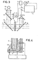
- FIG. 3 Its main characteristic is that the auxiliary beam is superimposed on the main beam to pass through the attenuating member.
- the main beam is parallel and monochromatic of wavelength ⁇ 0 .
- the attenuating member 1 provided with its control 3, inserted on the path of the main beam 4.
- the auxiliary beam comes from a light source S ( ⁇ 1 ) shown in 15. It is, for example, a light-emitting diode which emits monochromatic radiation of wavelength ⁇ , different from ⁇ 0 .
- All or part of the radiation from the source S ( ⁇ 1 ) is collected on a lens 16, so as to create a parallel light beam, for example of the same section as the main beam. Part of this bundle is taken using a semi-transparent blade 17, the sampling coefficient of which is known. This sampled part is sent via the lens 7 to the photodetector 8, which creates an electrical reference signal d l , proportional to the intensity of the auxiliary beam before attenuation.
- this auxiliary beam is made collinear with the main beam by means of a dichroic mirror 18 which fully transmits the radiation of wavelength ⁇ 0 and which completely reflects the radiation of wavelength ⁇ 1 .
- the wavelengths ⁇ 0 and ⁇ 1 can only be separated by a hundred angstroms.
- This auxiliary beam then crosses the attenuating member 1 along the same section as the main beam, which is advantageous since the attenuation may not be uniform over the entire surface of this member. It is then separated from the main beam by a second dichroic mirror 19, and sent to the lens 9 which focuses it on the second photodetector 10. This photodetector 10 creates an electrical signal d 2 , proportional to the intensity of the auxiliary beam after attenuation.
- This device allows automatic piloting as described above.
- the first relates to the auxiliary optical path section consisting of the source 15, the lens 16, the semi-transparent plate 17, the lens 7 and the photodetector 8.
- This section can be replaced by an integrated device, for example that which is described in patent No. 74 23 408 filed on July 5, 1974, entitled "Light emitting diode control device and optical communication system comprising such a device".
- This device shown in FIG. 4, supplies an optical fiber F with radiation from a light-emitting diode L, the intensity of which is measured by means of the photodetector P.
- These elements made integral with a support S, at by means of a sealing material 100 are electrically controlled by the supply box A.
- the second variant concerns the dichroic mirror 18 visible in FIG. 3. If the attenuation which one wishes to obtain on the main beam makes it possible to lose a known part of the intensity of this beam, and if one may also lose a part, also known, of the auxiliary beam, this dichroic mirror 18 can be replaced by a semi-transparent blade which is of a lower cost price.
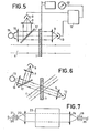
- FIG. 5 Another configuration of the device according to the invention is shown in FIG. 5.
- the auxiliary optical beam here crosses the attenuating member 1, next to the main beam 4, and is never confused with it. This configuration is only possible if the attenuating member is sufficiently uniform over its entire surface, but it is valid for a beam which is not necessarily monochromatic, and if it is, the wavelength of the beam auxiliary can be the same as that of the main beam.
- the auxiliary source 15 emits radiation towards the lens 16 to form a parallel beam. A part of this beam is taken by the semi-transparent plate, and sent via the lens 7 to the photodetector 8.
- the other part of the beam crosses the attenuating member 1 in an area close to that which is crossed by the main beam and is collected on the lens 9 which focuses it on the second photodetector 10.
- this device can be controlled automatically.
- FIG. 6 Another configuration is shown in FIG. 6. The only difference with the previous configuration is that the auxiliary optical beam crosses the attenuating member with a different incidence from the incidence of the main beam. The beams can overlap in the same area and the two beams do not interfere.
- This configuration combines the advantages of the other two, that is to say crossing the attenuator in the same area, using the same wavelength for the auxiliary source and removing dichroic mirrors.
- the nature of the attenuating organ lends itself to attenuation measures from different angles of incidence. Attenuators liquid crystal, for example, can meet this condition, and are therefore usable in this configuration.
- One area of application of this device is transmission by optical fibers.
- FIG. 7 represents an arrangement illustrating this integration.
- the input optical fiber 20 is connected to the device by an optical coupling means, constituted for example as in FIG. 7, by a detachable connector 21 and a lens 22, which forms a parallel beam from the light from the fiber.
- This beam passes through the attenuator 23 and is focused by the lens 24 on the output fiber 25 attached to the attenuator by the connector 26.
Landscapes
- Physics & Mathematics (AREA)
- Nonlinear Science (AREA)
- General Physics & Mathematics (AREA)
- Optics & Photonics (AREA)
- Optical Couplings Of Light Guides (AREA)
- Optical Communication System (AREA)
- Photometry And Measurement Of Optical Pulse Characteristics (AREA)
- Light Guides In General And Applications Therefor (AREA)
- Liquid Crystal (AREA)
Applications Claiming Priority (2)
| Application Number | Priority Date | Filing Date | Title |
|---|---|---|---|
| FR7928693 | 1979-11-21 | ||
| FR7928693A FR2470397A1 (fr) | 1979-11-21 | 1979-11-21 | Attenuateur optique a attenuation controlee |
Publications (1)
| Publication Number | Publication Date |
|---|---|
| EP0029777A1 true EP0029777A1 (de) | 1981-06-03 |
Family
ID=9231943
Family Applications (1)
| Application Number | Title | Priority Date | Filing Date |
|---|---|---|---|
| EP80401645A Withdrawn EP0029777A1 (de) | 1979-11-21 | 1980-11-17 | Optische Vorrichtung zur einstellbaren Schwächung des Lichts |
Country Status (5)
| Country | Link |
|---|---|
| US (1) | US4378490A (de) |
| EP (1) | EP0029777A1 (de) |
| JP (1) | JPS5687018A (de) |
| CA (1) | CA1155678A (de) |
| FR (1) | FR2470397A1 (de) |
Cited By (1)
| Publication number | Priority date | Publication date | Assignee | Title |
|---|---|---|---|---|
| EP0096615B1 (de) * | 1982-05-27 | 1986-08-20 | SOURIAU & Cie (S.A.) | Optischer Schalter |
Families Citing this family (18)
| Publication number | Priority date | Publication date | Assignee | Title |
|---|---|---|---|---|
| US4443696A (en) * | 1981-08-28 | 1984-04-17 | John Taboada | Optical beam intensity control system |
| FR2570836B1 (fr) * | 1984-09-21 | 1987-11-20 | Thomson Csf | Dispositif a ligne a retard optique circulante |
| US4690555A (en) * | 1985-11-01 | 1987-09-01 | Hughes Aircraft Company | Solid-state wavefront slope determination |
| DE3634508C1 (en) * | 1986-10-09 | 1988-06-16 | Rupert Fuerthbauer | Optical filter with automatic control of the optical transmission |
| WO1988007700A1 (en) * | 1987-03-30 | 1988-10-06 | Anritsu Corporation | Light signal generator and light power meter calibration system using the same |
| US5070235A (en) * | 1990-06-18 | 1991-12-03 | General Signal Corporation | Accumulated exposure detection with exposure terminating attenuator |
| JP2953799B2 (ja) * | 1991-03-04 | 1999-09-27 | 日本電気株式会社 | 光受信回路 |
| US5319733A (en) * | 1992-01-02 | 1994-06-07 | Adc Telecommunications, Inc. | Variable fiber optical attenuator |
| AU671599B2 (en) * | 1992-01-02 | 1996-09-05 | Adc Telecommunications, Incorporated | Overlapping fusion attenuator |
| US5881199A (en) * | 1996-12-02 | 1999-03-09 | Lucent Technologies Inc. | Optical branching device integrated with tunable attenuators for system gain/loss equalization |
| JPH1196578A (ja) * | 1997-09-19 | 1999-04-09 | Nec Corp | 光情報検出装置 |
| DE19906769A1 (de) * | 1998-02-19 | 1999-12-16 | Leica Microsystems | Überlastschutz zur Vermeidung einer Beschädigung optischer Komponenten |
| US6442311B1 (en) | 1999-07-09 | 2002-08-27 | Agere Systems Guardian Corp. | Optical device having modified transmission characteristics by localized thermal treatment |
| US6388730B1 (en) | 1999-11-19 | 2002-05-14 | Corning Incorporated | Lateral field based liquid crystal electro-optic polarizer |
| US6600594B1 (en) | 2002-02-21 | 2003-07-29 | Lightech Fiberoptics, Inc. | Intelligent variable optical attenuator with controller and attenuation calibration |
| DE102014208792A1 (de) * | 2014-05-09 | 2015-11-12 | Carl Zeiss Smt Gmbh | System und Verfahren zur Analyse eines von einer Strahlführungsoptik geführten Lichtstrahls |
| JP6370766B2 (ja) * | 2015-11-13 | 2018-08-08 | ファナック株式会社 | レーザ用パワーセンサ |
| TWI711807B (zh) * | 2018-09-18 | 2020-12-01 | 廣達電腦股份有限公司 | 照度校正裝置、照度校正方法以及照度偵測方法 |
Citations (5)
| Publication number | Priority date | Publication date | Assignee | Title |
|---|---|---|---|---|
| FR1540783A (fr) * | 1967-10-13 | 1968-09-27 | Cary Instruments | Dispositif de commande automatique pour modulateur de lumière |
| GB1222551A (en) * | 1968-02-28 | 1971-02-17 | Philips Nv | Arrangement for controlling a supply voltage to an electro-optical polarisation switch |
| US4071751A (en) * | 1976-04-26 | 1978-01-31 | Rca Limited | Automatic optical bias control for light modulators |
| US4119842A (en) * | 1977-06-17 | 1978-10-10 | General Motors Corporation | Heater control system for liquid crystal device |
| US4162398A (en) * | 1976-09-14 | 1979-07-24 | Victor Company Of Japan, Limited | Bias control circuit for light modulators |
Family Cites Families (2)
| Publication number | Priority date | Publication date | Assignee | Title |
|---|---|---|---|---|
| DE2403501C3 (de) * | 1974-01-25 | 1979-02-22 | Fa. Carl Zeiss, 7920 Heidenheim | Verfahren zur Regelung der Phasenanpassung einer kohärenten Sekundärstrahlung in einem nichtlinearen Kristall |
| JPS605926B2 (ja) * | 1978-11-22 | 1985-02-14 | 三菱電機株式会社 | 光変調装置 |
-
1979
- 1979-11-21 FR FR7928693A patent/FR2470397A1/fr active Granted
-
1980
- 1980-11-17 EP EP80401645A patent/EP0029777A1/de not_active Withdrawn
- 1980-11-18 US US06/208,001 patent/US4378490A/en not_active Expired - Lifetime
- 1980-11-18 CA CA000364931A patent/CA1155678A/en not_active Expired
- 1980-11-21 JP JP16447780A patent/JPS5687018A/ja active Pending
Patent Citations (5)
| Publication number | Priority date | Publication date | Assignee | Title |
|---|---|---|---|---|
| FR1540783A (fr) * | 1967-10-13 | 1968-09-27 | Cary Instruments | Dispositif de commande automatique pour modulateur de lumière |
| GB1222551A (en) * | 1968-02-28 | 1971-02-17 | Philips Nv | Arrangement for controlling a supply voltage to an electro-optical polarisation switch |
| US4071751A (en) * | 1976-04-26 | 1978-01-31 | Rca Limited | Automatic optical bias control for light modulators |
| US4162398A (en) * | 1976-09-14 | 1979-07-24 | Victor Company Of Japan, Limited | Bias control circuit for light modulators |
| US4119842A (en) * | 1977-06-17 | 1978-10-10 | General Motors Corporation | Heater control system for liquid crystal device |
Cited By (1)
| Publication number | Priority date | Publication date | Assignee | Title |
|---|---|---|---|---|
| EP0096615B1 (de) * | 1982-05-27 | 1986-08-20 | SOURIAU & Cie (S.A.) | Optischer Schalter |
Also Published As
| Publication number | Publication date |
|---|---|
| US4378490A (en) | 1983-03-29 |
| FR2470397B1 (de) | 1983-09-16 |
| JPS5687018A (en) | 1981-07-15 |
| FR2470397A1 (fr) | 1981-05-29 |
| CA1155678A (en) | 1983-10-25 |
Similar Documents
| Publication | Publication Date | Title |
|---|---|---|
| EP0029777A1 (de) | Optische Vorrichtung zur einstellbaren Schwächung des Lichts | |
| EP0021945B1 (de) | Durch elasto-optischen Effekt funktionierendes Hydrophon mit Monomode-Lichtleitfaser | |
| EP0025586B1 (de) | Vorrichtung für optische Kupplung | |
| EP0291394B1 (de) | Bewegungssensor mit zurückgesetzten optischen Fasern | |
| CA2092242C (fr) | Filtre optique comprenant un interferometre fabry-perot accordable par rotation | |
| FR2580072A1 (de) | ||
| EP3520182B1 (de) | Lasersystem mit optischer rückkopplung | |
| FR2520504A1 (fr) | Capteur de temperature a fibre optique | |
| FR2699295A1 (fr) | Dispositif de traitement optique de signaux électriques. | |
| WO2014087099A1 (fr) | Dispositif de mesure et de controle du front d'onde d'un faisceau lumineux coherent | |
| FR2750271A1 (fr) | Dispositif de controle de longueurs d'onde optiques | |
| FR2772150A1 (fr) | Modulateur optique utilisant un isolateur et transmetteur optique comprenant le susdit | |
| FR2495315A1 (fr) | Dispositif de mesure a fibres optiques | |
| EP0018873B1 (de) | Kompakte optische Koppelungsvorrichtung und solch eine Vorrichtung enthaltender interferometrischer Gyrometer mit einer optischen Faser | |
| FR2647552A1 (fr) | Systeme de mesure de signaux electriques a l'aide d'impulsions optiques ultracourtes | |
| FR2737779A1 (fr) | Dispositif ellipsometre a haute resolution spatiale | |
| EP1674878B1 (de) | Elektrooptische Sonde zur Messung elektrischer oder elektromagnetischer Felder mit einer Steuerung der Wellenlänge des Betriebspunkts | |
| FR2728678A1 (fr) | Capteur du type modulation optique et appareil d'instrumentation de processus utilisant celui-ci | |
| EP0152706A1 (de) | Polarisationsfernmessgerät | |
| FR2472880A1 (fr) | Dispositif de controle automatique de gain a action optique dans un systeme de transmission de signaux electriques par liaison optique | |
| FR2657161A1 (fr) | Dispositif de detection a distance d'une grandeur physique, fonctionnant en reflexion. | |
| EP0795778A1 (de) | Nichtlineare optische Signalverarbeitungseinrichtung | |
| FR2725788A1 (fr) | Refractometre a fibre optique realise en optique guidee | |
| EP0101997A1 (de) | Anordnung zum Messen der Dicke eines auf einem transparenten Substrat niedergeschlagenen Schicht | |
| FR2772135A1 (fr) | Dispositif pour mesurer la distance d'une cible |
Legal Events
| Date | Code | Title | Description |
|---|---|---|---|
| PUAI | Public reference made under article 153(3) epc to a published international application that has entered the european phase |
Free format text: ORIGINAL CODE: 0009012 |
|
| AK | Designated contracting states |
Designated state(s): DE GB IT NL SE |
|
| 17P | Request for examination filed |
Effective date: 19810810 |
|
| STAA | Information on the status of an ep patent application or granted ep patent |
Free format text: STATUS: THE APPLICATION IS DEEMED TO BE WITHDRAWN |
|
| 18D | Application deemed to be withdrawn |
Effective date: 19850103 |
|
| RIN1 | Information on inventor provided before grant (corrected) |
Inventor name: D'AURIA, LUIGI |