EP0029775B1 - Installation de centrale nucléaire, et procédé pour l'édification d'une telle centrale - Google Patents
Installation de centrale nucléaire, et procédé pour l'édification d'une telle centrale Download PDFInfo
- Publication number
- EP0029775B1 EP0029775B1 EP80401632A EP80401632A EP0029775B1 EP 0029775 B1 EP0029775 B1 EP 0029775B1 EP 80401632 A EP80401632 A EP 80401632A EP 80401632 A EP80401632 A EP 80401632A EP 0029775 B1 EP0029775 B1 EP 0029775B1
- Authority
- EP
- European Patent Office
- Prior art keywords
- buildings
- building
- raft
- reactor
- reactor building
- Prior art date
- Legal status (The legal status is an assumption and is not a legal conclusion. Google has not performed a legal analysis and makes no representation as to the accuracy of the status listed.)
- Expired
Links
- 238000000034 method Methods 0.000 title claims description 9
- 238000010276 construction Methods 0.000 claims description 22
- 239000000446 fuel Substances 0.000 claims description 14
- 238000009417 prefabrication Methods 0.000 claims description 6
- 230000001681 protective effect Effects 0.000 claims description 6
- 238000001816 cooling Methods 0.000 claims description 4
- 239000002915 spent fuel radioactive waste Substances 0.000 claims 1
- 238000009434 installation Methods 0.000 description 13
- XLYOFNOQVPJJNP-UHFFFAOYSA-N water Substances O XLYOFNOQVPJJNP-UHFFFAOYSA-N 0.000 description 4
- 238000004519 manufacturing process Methods 0.000 description 3
- 230000008520 organization Effects 0.000 description 2
- 241001080024 Telles Species 0.000 description 1
- 230000000712 assembly Effects 0.000 description 1
- 238000000429 assembly Methods 0.000 description 1
- 230000004888 barrier function Effects 0.000 description 1
- 238000009412 basement excavation Methods 0.000 description 1
- 230000003749 cleanliness Effects 0.000 description 1
- 238000004891 communication Methods 0.000 description 1
- 235000009508 confectionery Nutrition 0.000 description 1
- 238000007796 conventional method Methods 0.000 description 1
- 230000002328 demineralizing effect Effects 0.000 description 1
- 238000013461 design Methods 0.000 description 1
- 230000006355 external stress Effects 0.000 description 1
- 239000012530 fluid Substances 0.000 description 1
- 238000002955 isolation Methods 0.000 description 1
- 230000035945 sensitivity Effects 0.000 description 1
- 239000000126 substance Substances 0.000 description 1
- 238000013519 translation Methods 0.000 description 1
Images


Classifications
-
- G—PHYSICS
- G21—NUCLEAR PHYSICS; NUCLEAR ENGINEERING
- G21C—NUCLEAR REACTORS
- G21C13/00—Pressure vessels; Containment vessels; Containment in general
-
- Y—GENERAL TAGGING OF NEW TECHNOLOGICAL DEVELOPMENTS; GENERAL TAGGING OF CROSS-SECTIONAL TECHNOLOGIES SPANNING OVER SEVERAL SECTIONS OF THE IPC; TECHNICAL SUBJECTS COVERED BY FORMER USPC CROSS-REFERENCE ART COLLECTIONS [XRACs] AND DIGESTS
- Y02—TECHNOLOGIES OR APPLICATIONS FOR MITIGATION OR ADAPTATION AGAINST CLIMATE CHANGE
- Y02E—REDUCTION OF GREENHOUSE GAS [GHG] EMISSIONS, RELATED TO ENERGY GENERATION, TRANSMISSION OR DISTRIBUTION
- Y02E30/00—Energy generation of nuclear origin
- Y02E30/30—Nuclear fission reactors
Definitions
- the present invention relates to a new installation of a nuclear power station and more particularly of a light water power station. It also relates to a process for the construction of such a power station.
- the general installation of a nuclear power plant has so far been organized around a central building known as a "reactor building" containing the reactor core and the loops of the primary cooling circuit, and in particular the steam generators.
- the reactor building generally appears, in known installations, as a tall concrete construction, in the form of a circular cylinder with a vertical axis.
- the building containing the electric turbogenerators or engine room, the building for the fuel, as well as the various auxiliaries are then distributed around the reactor building.
- Such buildings can be constructed on raft (Brown Boveri Revue, volume 63 n ° 1, 1976, pages 54-65, N. SCHARFF et al. "Graben 1200 MW Nuclear Power Plant”.
- the first stage is that of the construction of the building itself, or the civil engineering execution phase. It includes the production of a concrete slab on which are mounted the various concrete elements such as biological barriers, the casemates of the steam generators, etc. At the top of the enclosure, a bridge is then mounted turning point which will first be used for the installation of heavy equipment then, during operation, for various handling.
- the second stage is that of installing heavy equipment, which can only be done after completion of the first stage.
- the cleanliness required for the equipment constituting the circulation loops of the primary fluid between the reactor core and the steam generators makes it impossible to carry out major civil engineering works in their vicinity.
- the rotary bridge it is currently necessary for the rotary bridge to be in place at the top of the enclosure in order to be able to install the heavy elements such as the tank, the pressurizer or the steam generators. Added to this is the fact that accessibility to the reactor building site is made difficult by the presence all around the construction sites of the annex buildings.
- the present invention leads to a general overall architecture of the various buildings of a nuclear power plant such that its resistance to earthquakes is increased and such that the various production operations can easily overlap each other, which allows a better organization of the site and a reduction in times and execution costs.
- all the buildings are arranged in a general T-shape, with the fuel and auxiliary buildings arranged in line and adjacent to each side of the reactor building, the machine building being arranged opposite of the reactor building and perpendicular to it and the reactor building, the fuel building and the auxiliary buildings are arranged on a common monobloc raft and are covered by a protective vault in the shape of a cylinder with horizontal generators parallel to the axis longitudinal of buildings rigidly connected to the raft following two generators, so as to constitute a monolithic tubular assembly where the vault is prestressed on the raft.
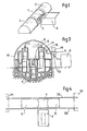
- FIG. 1 the general organization of the T-shaped power plant, with the reactor building 1 in the center, extended on both sides and in the same alignment, by the building 2 nuclear auxiliaries and building 3 of the electrical and backup auxiliaries.
- the reactor building here comprises four cooling loops and four casemates 5 for the outlet of the steam pipes to the engine room 6.
- FIGs 2 and 3 show in more detail the internal layout of the buildings, and more particularly of the reactor building.
- the vessel 7 of the reactor core there is the vessel 7 of the reactor core, with an overhead crane 8 for internal handling of the equipment and the reactor pool 9.
- Each primary water circulation loop between the core 7 and a steam generator 10, with a circulation pump, is here represented very schematically by a block 11, from which a steam pipe 12 starts.
- a main isolation valve 13 in a casemate 5 after crossing the protective enclosure 15.
- the series of safety valves will be arranged at 16 above the casemate.
- Zone 21 of building 2 constitutes a first nuclear auxiliary building, with make-up water and the volumetric and chemical control circuit of the primary circuit.
- Zone 22 also for nuclear auxiliaries, includes demineralizing filters and the effluent treatment circuit.
- building 3 On the other side of the reactor building, building 3 includes the electrical auxiliaries 24 and the backup auxiliaries 25.
- the raft 28 comprising the tank well 29, and straight feet. 30, then any backfill.
- a single raft is made for the reactor building and the auxiliary buildings which surround it, to obtain a monolithic assembly resistant to earthquakes.
- Service tracks 33 are then built at the edge, in parallel and on either side of the raft, and intended to allow the movement of cranes or any other means of lifting and transport.
- the tracks 33 are extended to two prefabrication sites 34, at each end of the overall site.
- FIG. 6 we will see the installation and assembly of the internal structures of the reactor building, such as for example the tank well and the casemates of the steam generators.
- the elements of these structures are prefabricated on one of the sites 34, then brought into place by means of light cranes 36 circulating on the tracks 33, and a large capacity crane 38.
- the elements can then be assembled by all conventional techniques.
- any type of lifting means suitable for the elements to be installed will be used, and the cranes shown in a simplified manner in the drawing could if necessary. be replaced by gantries spanning the entire width of the raft.
- FIG. 6 shows the positioning of the tank 7 by means of the crane 38. The same would apply to the positioning of the steam generators, the pressurizer and the pumps.
- the vault can be made by prefabricated elements each constituting the self-supporting sections. Each element to be juxtaposed to constitute the enclosure can be prefabricated on one of the sites 34, then brought on site to the reactor building by simple translation along the tracks 33. We will see more particularly in Figure 7 such an element 41 carried by carriages 42. Once in the correct longitudinal position the element can be taken up on jacks to release the carriages, then lowered to its final position shown in phantom.
- the vault After installation, the vault is rigidly secured to the raft to obtain a tubular assembly whose thick lower part is formed by the raft, and which facilitates the prestressing of the continuous vault.
- the installation of the superstructures of the auxiliary buildings can be carried out in the same way, the operations for the reactor building as for the auxiliary buildings being able to be carried out by the two ends at the same time.
- a continuous tubular construction is thus obtained, the earthquake resistance of which allows both the protection of the reactor building and of the fuel and auxiliary buildings.
- the embodiment of the power plant as just described makes it possible not only to save time when running the site, but also to reduce the height under the roof of the power plant since this height does not depend more space needed to right steam generators; the power plant will then have better resistance to earthquakes, not only because of its continuous and prestressed tubular structure but also because of its lower height.
- any other method of constructing the vault of the protective enclosure of the reactor building other than the constitution of self-supporting elements provided that these other methods which may be customary, lend themselves to prefabrication and to a easy assembly on site.
Landscapes
- Physics & Mathematics (AREA)
- Engineering & Computer Science (AREA)
- Plasma & Fusion (AREA)
- General Engineering & Computer Science (AREA)
- High Energy & Nuclear Physics (AREA)
- Structure Of Emergency Protection For Nuclear Reactors (AREA)
- Conveying And Assembling Of Building Elements In Situ (AREA)
Applications Claiming Priority (2)
| Application Number | Priority Date | Filing Date | Title |
|---|---|---|---|
| FR7928067 | 1979-11-14 | ||
| FR7928067A FR2469778A1 (fr) | 1979-11-14 | 1979-11-14 | Installation de centrale nucleaire, et procede pour l'edification d'une telle centrale |
Publications (2)
| Publication Number | Publication Date |
|---|---|
| EP0029775A1 EP0029775A1 (fr) | 1981-06-03 |
| EP0029775B1 true EP0029775B1 (fr) | 1984-02-15 |
Family
ID=9231667
Family Applications (1)
| Application Number | Title | Priority Date | Filing Date |
|---|---|---|---|
| EP80401632A Expired EP0029775B1 (fr) | 1979-11-14 | 1980-11-14 | Installation de centrale nucléaire, et procédé pour l'édification d'une telle centrale |
Country Status (5)
| Country | Link |
|---|---|
| US (2) | US4416849A (https=) |
| EP (1) | EP0029775B1 (https=) |
| DE (1) | DE3066640D1 (https=) |
| ES (1) | ES8507720A1 (https=) |
| FR (1) | FR2469778A1 (https=) |
Families Citing this family (11)
| Publication number | Priority date | Publication date | Assignee | Title |
|---|---|---|---|---|
| FR2469778A1 (fr) * | 1979-11-14 | 1981-05-22 | Framatome Sa | Installation de centrale nucleaire, et procede pour l'edification d'une telle centrale |
| JP2750368B2 (ja) * | 1989-09-28 | 1998-05-13 | 株式会社日立製作所 | 原子炉格納容器トップスラブの構築方法 |
| WO2010085359A2 (en) * | 2009-01-26 | 2010-07-29 | Petrovich Svetozar B | Fluid elements |
| RU2188466C2 (ru) * | 2000-01-11 | 2002-08-27 | Федеральное Государственное Унитарное Предприятие "Санкт-Петербургское Морское Бюро Машиностроения "Малахит" | Плавучая атомная электростанция |
| JP4237445B2 (ja) * | 2001-04-27 | 2009-03-11 | 日立Geニュークリア・エナジー株式会社 | 構造物の取扱方法 |
| RU2218614C2 (ru) * | 2002-01-03 | 2003-12-10 | Общество с ограниченной ответственностью "ТВЭЛЛ" | Подземная атомная станция энергоснабжения и способ ее эксплуатации |
| WO2010021352A1 (ja) | 2008-08-22 | 2010-02-25 | 東芝プラントシステム株式会社 | 機器の据付方法並びにアンカー部材支持機構及びアンカーボルトユニット |
| JP5260268B2 (ja) * | 2008-12-26 | 2013-08-14 | 日立Geニュークリア・エナジー株式会社 | 原子力発電プラント用炉心シュラウドの製造方法及び原子力発電プラント構造物 |
| WO2012096937A1 (en) * | 2011-01-10 | 2012-07-19 | Arcelormittal Investigacion Y Desarrollo S.L. | Method of welding nickel-aluminide |
| JP6916239B2 (ja) * | 2015-05-25 | 2021-08-11 | 日立Geニュークリア・エナジー株式会社 | 原子炉建屋全体カバー装置及び原子炉建屋準備作業方法 |
| RU2729926C1 (ru) * | 2019-01-10 | 2020-08-13 | Федеральное государственное унитарное предприятие "Российский федеральный ядерный центр - Всероссийский научно-исследовательский институт технической физики имени академика Е.И. Забабахина" | Мобильный модульный комплекс жизнеобеспечения |
Family Cites Families (18)
| Publication number | Priority date | Publication date | Assignee | Title |
|---|---|---|---|---|
| US3395076A (en) * | 1966-02-23 | 1968-07-30 | Westinghouse Electric Corp | Compact nuclear reactor heat exchanging system |
| DE2134420C3 (de) * | 1966-10-11 | 1974-10-03 | Licentia Patent-Verwaltungs-Gmbh, 6000 Frankfurt | Kugelförmiger Sicherheitsbehälter für Atomkernreaktoren |
| US3436052A (en) * | 1967-11-02 | 1969-04-01 | Technical Investment Corp | Mold for forming monolithic concrete cylindrical building |
| FR1572466A (https=) * | 1968-05-06 | 1969-06-27 | ||
| US3752738A (en) * | 1970-07-06 | 1973-08-14 | Nuclear Services Corp | Nuclear reactor plant and multiple purpose shielding system therefor |
| US4065905A (en) * | 1972-08-21 | 1978-01-03 | Lely Cornelis V D | Prefabricated building sections or room units and methods for the manufacture of such sections or units |
| US4015383A (en) * | 1973-11-23 | 1977-04-05 | Crowley Francis X | Concrete tank of precast concrete panels with pretensioning beam means |
| GB1517479A (en) * | 1975-07-02 | 1978-07-12 | Westinghouse Electric Corp | Vehicle including a nuclear power generator arrangement |
| DE2634295C3 (de) * | 1976-07-30 | 1979-04-19 | Kraftwerk Union Ag, 4330 Muelheim | Kernreaktoranlage |
| US4187659A (en) * | 1976-09-07 | 1980-02-12 | North Oakland Development Corporation | Home building method and apparatus |
| DE2704750A1 (de) * | 1977-02-04 | 1978-08-10 | Kraftwerk Union Ag | Berstgeschuetzte kernreaktoranlage |
| US4257846A (en) * | 1978-01-19 | 1981-03-24 | Westinghouse Electric Corp. | Bi-brayton power generation with a gas-cooled nuclear reactor |
| US4198797A (en) * | 1978-05-01 | 1980-04-22 | Soble Bernard D | Method and fixture for lateral and longitudinal positioning of mobile or modular home units |
| FI71030C (fi) * | 1978-06-23 | 1986-10-27 | Mo Inzh Str Kb | Kaernreaktorschakt |
| SE417342B (sv) * | 1979-02-05 | 1981-03-09 | Nya Asfalt Ab | Forfarande och anordning for grundleggning av for tillverkade anleggningar i land |
| US4302291A (en) * | 1979-05-03 | 1981-11-24 | Severs Stephen B | Underwater nuclear power plant structure |
| FR2469778A1 (fr) * | 1979-11-14 | 1981-05-22 | Framatome Sa | Installation de centrale nucleaire, et procede pour l'edification d'une telle centrale |
| FR2495371A1 (fr) * | 1980-11-28 | 1982-06-04 | Framatome Sa | Batiment reacteur comportant des structures internes dont les sollicitations sont independantes des deformations du radier general, et procede pour la realisation de ces structures internes |
-
1979
- 1979-11-14 FR FR7928067A patent/FR2469778A1/fr active Granted
-
1980
- 1980-10-06 US US06/194,131 patent/US4416849A/en not_active Expired - Lifetime
- 1980-10-24 ES ES496225A patent/ES8507720A1/es not_active Expired
- 1980-11-14 EP EP80401632A patent/EP0029775B1/fr not_active Expired
- 1980-11-14 DE DE8080401632T patent/DE3066640D1/de not_active Expired
-
1983
- 1983-06-22 US US06/506,920 patent/US4627213A/en not_active Expired - Fee Related
Also Published As
| Publication number | Publication date |
|---|---|
| US4416849A (en) | 1983-11-22 |
| EP0029775A1 (fr) | 1981-06-03 |
| ES496225A0 (es) | 1985-09-01 |
| ES8507720A1 (es) | 1985-09-01 |
| US4627213A (en) | 1986-12-09 |
| DE3066640D1 (en) | 1984-03-22 |
| FR2469778A1 (fr) | 1981-05-22 |
| FR2469778B1 (https=) | 1982-06-25 |
Similar Documents
| Publication | Publication Date | Title |
|---|---|---|
| EP0029775B1 (fr) | Installation de centrale nucléaire, et procédé pour l'édification d'une telle centrale | |
| CN102733637B (zh) | 组装套架结构的方法 | |
| CN103194981B (zh) | 桥梁钢塔海上竖转施工系统及方法 | |
| AU2005202963A1 (en) | Wind turbine power module mounted on the tower foundation | |
| CA2331237C (en) | Partially prefabricated waffle slab | |
| ES8604669A1 (es) | Una disposicion de guia de conductores para conductores de una plataforma para pozos marinos. | |
| EP0358945B1 (en) | Method of assembling wound rotor of vertical type adjustable speed hydroelectric rotating machine at its installation site | |
| US4630968A (en) | Realization procedure of a modular system particularly suitable for use off coasts | |
| NO157463B (no) | Fremgangsmaate for aa bygge en offshore-taarnkonstruksjon. | |
| KR20090076796A (ko) | 횡방향 스키딩을 이용하여 하나 이상의 반 잠수형 리그의동시 건조 방법 | |
| EP0863260B1 (fr) | Procédé d'assemblage de tronçons de jambes de support d'une plate-forme pétrolière | |
| CN206143801U (zh) | 一种适应多种环境条件的光伏箱逆变基础 | |
| WO1980001662A1 (fr) | Dispositif pour l'installation d'un bloc formant reacteur nucleaire dans un navire | |
| CA3019870C (fr) | Ensemble pour la construction d'un reacteur nucleaire et procedes correspondants | |
| CN215759171U (zh) | 一种能够转弯的预制电缆工作井 | |
| MC823A1 (fr) | Procédé de construction d'un bâtiment partiellement submergé et bâtiment réalisé suivant ce procédé | |
| JP6004394B2 (ja) | 重量機器の据付工法 | |
| EP0055647A1 (fr) | Machine pour le contrôle sur leur poste de stockage des équipements internes d'un réacteur nucléaire | |
| NO173816B (no) | Fremgangsmaate ved oppbygging av en offshore-konstruksjon | |
| CN223433798U (zh) | 一种钢围堰吊装、下放平台 | |
| CN120793371A (zh) | 一种旋转收缩式海上光伏支架叠拼工装及其驳运作业方法 | |
| FR2474992A1 (fr) | Dispositif flottant pour travaux en mer | |
| CN220394628U (zh) | 一种带附属预制构件的电梯基础 | |
| JPH08165662A (ja) | 地下構造物の構築方法 | |
| FR3151127A1 (fr) | Methode de construction d’une installation nucleaire enterree |
Legal Events
| Date | Code | Title | Description |
|---|---|---|---|
| PUAI | Public reference made under article 153(3) epc to a published international application that has entered the european phase |
Free format text: ORIGINAL CODE: 0009012 |
|
| AK | Designated contracting states |
Designated state(s): BE CH DE IT |
|
| 17P | Request for examination filed |
Effective date: 19810417 |
|
| ITF | It: translation for a ep patent filed | ||
| GRAA | (expected) grant |
Free format text: ORIGINAL CODE: 0009210 |
|
| AK | Designated contracting states |
Designated state(s): BE CH DE IT LI |
|
| REF | Corresponds to: |
Ref document number: 3066640 Country of ref document: DE Date of ref document: 19840322 |
|
| PLBE | No opposition filed within time limit |
Free format text: ORIGINAL CODE: 0009261 |
|
| STAA | Information on the status of an ep patent application or granted ep patent |
Free format text: STATUS: NO OPPOSITION FILED WITHIN TIME LIMIT |
|
| 26N | No opposition filed | ||
| ITTA | It: last paid annual fee | ||
| PGFP | Annual fee paid to national office [announced via postgrant information from national office to epo] |
Ref country code: CH Payment date: 19941121 Year of fee payment: 15 |
|
| PGFP | Annual fee paid to national office [announced via postgrant information from national office to epo] |
Ref country code: BE Payment date: 19941123 Year of fee payment: 15 |
|
| PGFP | Annual fee paid to national office [announced via postgrant information from national office to epo] |
Ref country code: DE Payment date: 19950131 Year of fee payment: 15 |
|
| PG25 | Lapsed in a contracting state [announced via postgrant information from national office to epo] |
Ref country code: LI Effective date: 19951130 Ref country code: CH Effective date: 19951130 Ref country code: BE Effective date: 19951130 |
|
| BERE | Be: lapsed |
Owner name: FRAMATOME Effective date: 19951130 |
|
| REG | Reference to a national code |
Ref country code: CH Ref legal event code: PL |
|
| PG25 | Lapsed in a contracting state [announced via postgrant information from national office to epo] |
Ref country code: DE Effective date: 19960903 |