EP0029585B1 - Method of clock adjustment for a digital audio signal on a data flow - Google Patents
Method of clock adjustment for a digital audio signal on a data flow Download PDFInfo
- Publication number
- EP0029585B1 EP0029585B1 EP80107201A EP80107201A EP0029585B1 EP 0029585 B1 EP0029585 B1 EP 0029585B1 EP 80107201 A EP80107201 A EP 80107201A EP 80107201 A EP80107201 A EP 80107201A EP 0029585 B1 EP0029585 B1 EP 0029585B1
- Authority
- EP
- European Patent Office
- Prior art keywords
- clock rate
- rate matching
- voice frequency
- superframe
- frequency signal
- Prior art date
- Legal status (The legal status is an assumption and is not a legal conclusion. Google has not performed a legal analysis and makes no representation as to the accuracy of the status listed.)
- Expired
Links
- 238000000034 method Methods 0.000 title claims abstract description 16
- 230000005236 sound signal Effects 0.000 title description 27
- 230000005540 biological transmission Effects 0.000 claims abstract description 31
- 230000011664 signaling Effects 0.000 claims abstract description 10
- 230000015572 biosynthetic process Effects 0.000 claims 1
- 230000006978 adaptation Effects 0.000 description 20
- 230000001360 synchronised effect Effects 0.000 description 6
- 238000006243 chemical reaction Methods 0.000 description 5
- 238000003780 insertion Methods 0.000 description 2
- 230000037431 insertion Effects 0.000 description 2
- 238000005070 sampling Methods 0.000 description 2
- 241001076195 Lampsilis ovata Species 0.000 description 1
- 230000000295 complement effect Effects 0.000 description 1
- 238000013213 extrapolation Methods 0.000 description 1
- 230000008054 signal transmission Effects 0.000 description 1
Images

Classifications
-
- H—ELECTRICITY
- H04—ELECTRIC COMMUNICATION TECHNIQUE
- H04J—MULTIPLEX COMMUNICATION
- H04J3/00—Time-division multiplex systems
- H04J3/02—Details
- H04J3/06—Synchronising arrangements
- H04J3/07—Synchronising arrangements using pulse stuffing for systems with different or fluctuating information rates or bit rates
Definitions
- the invention relates to a method for clock adaptation for a sound signal present in digital form to a data flow organized in frames and superframes for digital voice transmission in telephony quality and with identification bits for identification transmission, whose clock is plesiochronous to the clock of the digital sound signal, which is one for the two clock frequencies minor deviation of, for example, 10- 4 to 10- 7 means.
- a number of clock adaptation methods are known for combining the data streams of a plurality of digital subsystems with plesiochronous clocks to form an upper system. These procedures can be divided into those with and without loss of information. If one wanted to consider a clock adjustment with loss of information for the application mentioned, this would mean the omission or repetition of an entire code word from time to time in order not to lose word synchronism. Studies have shown that from this measure, one would not result from the listener to accepting loss of quality of the audio signal when the clock deviation is greater than 10. 7
- the multiplex system which became known through the " Taschenbuch der Fernmeldepraxis 1979", pp. 13 to 41, is suitable both for the digital transmission of sound signals and for the combined transmission of sound and telephone signals in the pulse frame of the DSV2.
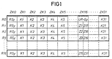
- Fig. 1 shows the known structure of the pulse frame and the superframe of a DSV2.
- This pulse frame of 125 us duration contains 256 bits; this corresponds to a data flow of 2048 kbit / s.
- the pulse frame is divided into 32 time channels, ZKO-ZK31.
- the first time channel ZKO is used alternately for the transmission of a message and a frame identification word (RSy).
- the seventeenth time channel ZK16 is mainly intended for the transmission of the dialing codes Z1-Z15, Z17-Z31 of the thirty telephone channels K1-K15, K17-K31.
- Sixteen consecutively transmitted pulse frames RO-R15 form an overframe.
- the superframe is synchronized by an overframe synchronization word ÜR-Sy in the seventeenth time channel ZK16 of the first pulse frame R0.
- the sixteen pulse frames of an overframe are drawn with one another in FIG. 1.
- the proposal which became known from the pocketbook of telecommunications practice, allows the DSV2 to be mixed with telephone and audio channels.
- the first time channels ZKO and the seventeenth time channels ZK16 are not affected by the sound transmission.
- the invention is based on the object of specifying a method for clock adaptation in which the start of the first code words of the digital audio signals within a pulse frame largely coincides with the start of the first time channel allocated for audio transmission, i.e. the first bit of the digital audio signals within a superframe is almost always the highest-valued bit of the code word.
- the subclaim relates to an advantageous development of the invention.
- the invention offers the advantage that a multiplex system provided for the transmission of synchronously coded audio channels can be used without changing the frame structure even when the clock generators involved are operating in a plesiochronous manner.
- the clock adaptation according to the invention makes it possible to leave the limits of the code words of the digital audio signal in the pulse frame largely unchanged and thereby to carry out rapid synchronization at the reception end in the event of transmission errors.
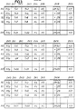
- each show three successive superframes, each consisting of sixteen pulse frames RO-R15, which in turn are made up of thirty-two time channels ZKO-ZK31, each with 8 bits.
- the time channels! EZK1 -ZK3 are assigned thirty-two audio signal words or code words Tn1-Tn32, each with 12 bits of a 7 kHz audio signal.
- the 3 by 4 bit positions that were released in the time channels ZK16 (originally the selection codes Z1-Z3 of 4 bits each in the pulse frames R1, R2 and R3) can be used for clock adaptation.
- the first 8 bits in the pulse frames R1 and R2 are alternately applied to a positive and a negative clock adjustment signal ++ or - per superframe.
- the clock adaptation signal ++ and / or is thus distributed over the pulse frames R1 and R2.
- the remaining 4 bit positions in the pulse frame R3 are claimed by a signal word S, which can be used, for example, for the transmission of alarms or for signaling purposes.
- Fig. 3 the case of a positive clock deviation is shown, i.e. the clock frequency of the audio signal is lower than the proportional clock frequency of the DSV2.
- positive clock adjustment signals are transmitted in two successive superframes and an informationless empty word LW is inserted in the second superframe, at a location agreed with the receiver, here the first code word after the frame identifier word RSy in the pulse frame R3 .
- the first code word after the frame identifier word RSy in the pulse frame R3 the first code word after the frame identifier word RSy in the pulse frame R3 .
- the first code word after the frame identifier word RSy in the pulse frame R3 .
- only one code word of the 7 kHz audio signal is transmitted in the pulse frame R3, and within this superframe the number of transmitted code words is reduced by 1 to 31.
- the synchronicity is thus restored, and in the subsequent superframes are alternated with and negative clock adjustment signal, starting with positive and negative clock adjustment signals.
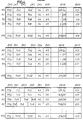
- the clock frequency of the audio signal is greater than the proportional clock frequency of the DSV2.
- negative clock adjustment signals are transmitted in two successive superframes. Since a codeword hidden from the audio signal must also be transmitted within a superframe, it has been agreed that the superframe following the superframe with the second negative clock adaptation signal (here the third superframe) contains 33 code words.
- the bit positions within the seventeenth time channel ZK16 that are otherwise used for a tone transmission for the clock adaptation signal and signal word S are in the pulse frame R1 with the first 4 bits of the code word Tn5, in the pulse frame R2 with the 5th to 8th bits of the code word Tn7 and in the pulse frame R3 with the last 4 bits of the code word Tn9 occupied.
- a resulting shift in the code word limits of Code words Tn5 to Tn9 within the pulse frames R2 and R3 are canceled in the fifth pulse frame, not shown, and a tenth code word begins at the first bit position of the time channel ZK1 in this pulse frame.
- the transmission of the codeword of the digital audio signal which is hidden on the transmission side is dispensed with and the time of the clock adaptation is only communicated to the receiver by the two successive negative clock adaptation signals.
- This replaces the hidden code word with an estimate that is either the same as the previous code word, an extrapolation of two or more previous code words, or the mean (geometric, arithmetic, etc.) of the code words adjacent to the hidden code word. In this case there is no interruption in the transmission of signal word S.
- a negative clock adaptation of the 15 kHz audio signal according to the example according to FIG. 4 also causes a shift in the code word limits within the time channels ZK17-ZK19, since in the pulse frame R1 4 bits of the bits to be transmitted normally in the time channel ZK17 and in the first half of the time channel ZK18 Code word are already transmitted in the time channel ZK16.
- This code word shift increases to 8 bits in the pulse frame R2 after the time channel ZK16 and becomes 12 bits in the pulse frame R3 after the time channel ZK16, so that the start of the code word in the time channels ZK17 and ZK18 coincides with the start of the time channel ZK17.
- the clock adaptation signals + + or - are 8-digit code words that are complementary to one another. Your Hamming distance is therefore 8. Therefore, up to three errors contained in these code words can be corrected.
- the method can be econcess g of the invention with known variable storing (Alinger) for hiding and displaying realizing of bit groups.
- the restoration of the original clock belonging to the coded audio signal is possible by means of a known PLL circuit with a low time constant in the control loop.
- This method can be used for clock adaptation for all coded analog signals, but in particular for picture and sound signals, regardless of the frame structure of the transmission system if only the frame has additional information capacity for signaling the clock adaptation signals.
Landscapes
- Engineering & Computer Science (AREA)
- Computer Networks & Wireless Communication (AREA)
- Signal Processing (AREA)
- Synchronisation In Digital Transmission Systems (AREA)
- Time-Division Multiplex Systems (AREA)
- Electrophonic Musical Instruments (AREA)
- Ultra Sonic Daignosis Equipment (AREA)
Abstract
Description
Die Erfindung betrifft ein Verfahren zur Taktanpassung für ein in digitaler Form vorliegendes Tonsignal an einen in Rahmen und Überrahmen organisierten Datenfluss zur digitalen Sprachübertragung in Telefoniequalität und mit Kennzeichenbits zur Kennzeichenübertragung, dessen Takt plesiochron zum Takt des digitalen Tonsignals ist, was für die beiden Taktfrequenzen eine zueinander geringfügige Abweichung von z.B. 10-4 bis 10-7 bedeutet.The invention relates to a method for clock adaptation for a sound signal present in digital form to a data flow organized in frames and superframes for digital voice transmission in telephony quality and with identification bits for identification transmission, whose clock is plesiochronous to the clock of the digital sound signal, which is one for the two clock frequencies minor deviation of, for example, 10- 4 to 10- 7 means.
Wird die Umsetzung eines analogen Tonrundfunksignals in digitale Form, z.B. mit dem Takt einer Digitalsignalverbindung für 2-Mbit/s-Signale (DSV2, bisher PCM30) gesteuert, ist die Einfügung des entstehenden Datenstromes in den Pulsrahmen der DSV2 und die Mitbenutzung der evtl. nachfolgenden weiteren digitalen Hierarchiestufen unproblematisch. Es sind jedoch Anwendungsfälle denkbar, bei denen die Analog/Digital-Umsetzung (A/D-Umsetzung) räumlich entfernt von den Geräten der DSV2 erfolgt und aus verschiedenen Gründen die Benutzung deren Taktes nicht möglich ist. Zur A/D-Umsetzung kann dann nur ein örtlich erzeugter Takt verwendet werden, der plesiochron zum Takt der DSV2 ist. In diesen Fällen ist eine Taktanpassung erforderlich.If the conversion of an analog audio broadcast signal into digital form, e.g. Controlled with the clock of a digital signal connection for 2 Mbit / s signals (DSV2, previously PCM30), the insertion of the resulting data stream into the pulse frame of the DSV2 and the shared use of any subsequent digital hierarchy levels is unproblematic. However, applications are conceivable in which the analog / digital conversion (A / D conversion) is spatially remote from the devices of the DSV2 and for various reasons the use of their clock is not possible. Only a locally generated clock can then be used for the A / D conversion, which is plesiochronous to the clock of the DSV2. In these cases a clock adjustment is necessary.
Zum Zusammenfassen der Datenströme mehrerer digitaler Untersysteme mit zueinander plesiochronen Takten zu einem Obersystem sind mehrere Taktanpassungsverfahren bekannt. Diese Verfahren lassen sich in solche mit und ohne Informationsverlust einteilen. Wollte man für den genannten Anwendungsfall eine Taktanpassung mit Informationsverlust in Betracht ziehen, so würde dies, um den Wortsynchronismus nicht zu verlieren, das Weglassen oder Wiederholen eines ganzen Codewortes von Zeit zu Zeit bedeuten. Untersuchungen haben ergeben, dass aus dieser Massnahme eine vom Zuhörer nicht zu akzeptierende Qualitätseinbusse des Tonsignals resultieren würde, wenn die Taktabweichung grösser als 10-7 ist.A number of clock adaptation methods are known for combining the data streams of a plurality of digital subsystems with plesiochronous clocks to form an upper system. These procedures can be divided into those with and without loss of information. If one wanted to consider a clock adjustment with loss of information for the application mentioned, this would mean the omission or repetition of an entire code word from time to time in order not to lose word synchronism. Studies have shown that from this measure, one would not result from the listener to accepting loss of quality of the audio signal when the clock deviation is greater than 10. 7
Taktanpassungsverfahren ohne Informationsverlust bei bitweiser Taktanpassung sind aus den "Nachrichtentechnischen Fachberichten", Nr. 42, 1972, PCM-Technik, VDE-Verlag GmbH Berlin-Charlottenburg, S. 235 bis 244, und aus der Zeitschrift "Elektronik", Heft 6/1978, S. 78 bis 83, bekannt. Dabei werden an vereinbarter Stelle im Rahmen - meist eines Obersystems - Leerbits eingefügt (positive Taktanpassung) oder Informationsbits ausgeblendet (negative Taktanpassung). Dieser Vorgang muss mittels im Pulsrahmen verfügbarer Zusatzkapazität dem Empfänger mitgeteilt werden, der die sendeseitig vorgenommene Manipulation rückgängig macht und den ursprünglichen Takt wieder erzeugt. Neben den Verfahren mit positiver Taktanpassung oder negativer Taktanpassung, bei denen beim ersten Verfahren die Taktfrequenz des Untersystems niedriger und beim zweiten Verfahren die Taktfrequenz des Untersystems höher als die Taktfrequenz des zur Verfügung stehenden Datenstromes ist, gibt es nach der zeitschrift "Frequenz", 32 (1978) 10, S. 281 bis 287, eine Kombination der beiden Möglichkeiten als positiv/negativ-Taktanpassung. Hierbei können relative Taktabweichungen in positiver und in negativer Richtung verarbeitet werden.Clock adjustment methods without loss of information with bitwise clock adjustment are from the " Telecommunications Technical Reports", No. 42, 1972, PCM technology, VDE-Verlag GmbH Berlin-Charlottenburg, pp. 235 to 244, and from the magazine " Electronics", issue 6/1978 , Pp. 78 to 83. In this case, empty bits are inserted at an agreed place in the frame - usually of an upper system (positive clock adjustment) or information bits are hidden (negative clock adjustment). This process must be communicated to the receiver by means of additional capacity available in the pulse frame, which cancels the manipulation carried out on the transmitter side and generates the original clock again. In addition to the methods with positive clock adaptation or negative clock adaptation, in which the clock frequency of the subsystem is lower in the first method and the clock frequency of the subsystem is higher than the clock frequency of the available data stream in the second method, according to the journal " Frequency", 32 ( 1978) 10, pp. 281 to 287, a combination of the two options as a positive / negative clock adjustment. Here, relative clock deviations in the positive and negative directions can be processed.
Das durch das "Taschenbuch der Fernmeldepraxis 1979", S. 13 bis 41, bekanntgewordene Multiplexsystem ist sowohl zur digitalen Übertragung von Tonsignalen als auch zur kombinierten Übertragung von Ton- und Fernsprechsignalen im Pulsrahmen der DSV2 geeignet.The multiplex system, which became known through the " Taschenbuch der Fernmeldepraxis 1979", pp. 13 to 41, is suitable both for the digital transmission of sound signals and for the combined transmission of sound and telephone signals in the pulse frame of the DSV2.
Fig. 1 zeigt den bekannten Aufbau des Pulsrahmens und des Überrahmens einer DSV2. Dieser Pulsrahmen von 125 us Dauer enthält 256 bit; das entspricht einem Datenfluss von 2048 kbit/s. Der Pulsrahmen ist in 32 Zeitkanäle, ZKO-ZK31, unterteilt. Der erste Zeitkanal ZKO dient alternierend zur Übertragung eines Melde- und eines Rahmenkennungswortes (RSy). Der siebzehnte Zeitkanal ZK16 ist hauptsächlich zur Übermittlung der Wahlkennzeichen Z1-Z15, Z17-Z31 der dreissig Fernsprechkanäle K1-K15, K17-K31 vorgesehen. Sechzehn nacheinander gesendete Pulsrahmen RO-R15 bilden einen Überrahmen. Die Synchronisierung des Überrahmens erfolgt durch ein Überrahmensynchronisierwort ÜR-Sy im siebzehnten Zeitkanal ZK16 des ersten Pulsrahmens R0. Der Übersichtlichkeit wegen sind die sechzehn Pulsrahmen eines Überrahmens in Fig. 1 untereinander gezeichnet.Fig. 1 shows the known structure of the pulse frame and the superframe of a DSV2. This pulse frame of 125 us duration contains 256 bits; this corresponds to a data flow of 2048 kbit / s. The pulse frame is divided into 32 time channels, ZKO-ZK31. The first time channel ZKO is used alternately for the transmission of a message and a frame identification word (RSy). The seventeenth time channel ZK16 is mainly intended for the transmission of the dialing codes Z1-Z15, Z17-Z31 of the thirty telephone channels K1-K15, K17-K31. Sixteen consecutively transmitted pulse frames RO-R15 form an overframe. The superframe is synchronized by an overframe synchronization word ÜR-Sy in the seventeenth time channel ZK16 of the first pulse frame R0. For the sake of clarity, the sixteen pulse frames of an overframe are drawn with one another in FIG. 1.
Der aus dem Taschenbuch der Fernmeldepraxis bekanntgewordene Vorschlag erlaubt die gemischte Belegung der DSV2 mit Fernsprech- und Tonkanälen. Die ersten Zeitkanäle ZKO und die siebzehnten Zeitkanäle ZK16 werden dabei durch die Tonübertragung nicht angetastet.The proposal, which became known from the pocketbook of telecommunications practice, allows the DSV2 to be mixed with telephone and audio channels. The first time channels ZKO and the seventeenth time channels ZK16 are not affected by the sound transmission.
Bei dieser digitalen Tonübertragung sind Kanäle hoher Qualität mit 15 kHz Bandbreite und solche einer mittleren Qualität mit 7 kHz Bandbreite zu berücksichtigen. Im ersten Fall beträgt die Abtastfrequenz 32 kHz und im zweiten Fall 16 kHz. Beides sind Vielfache der Abtastfrequenz von 8 kHz für Fernsprechsignale. Jeder Abtastwert mit den Schutzbits gegen die auf dem Übertragungsweg entstehenden Bitfehler beansprucht ein Wort von 12 bit Länge. In einem Pulsrahmen müssen daher für einen 15-kHz-Tonkanal vier Codeworte zu je 12 bit und für einen 7-kHz-Tonkanal zwei Codeworte zu je 12 bit untergebracht werden. Bei der Übertragung eines 15-kHz-Tonkanals werden deshalb sechs Zeitkanäie ZK1 -ZK3, ZK17-ZK19 zu je 8 bit und bei der Übertragung eines 7-kHz-Tonsignals drei Zeitkanäle ZK1 -ZK3 belegt. Sollen weitere Tonkanäle übertragen werden, so werden weitere Zeitkanäle ZK4-ZK6, ZK20-ZK22 bzw. ZK4-ZK6 usw. belegt. Die Bis von zwei aufeinanderfolgenden Codeworten werden zusätzlich zum Schutz gegen Doppelfehler auf dem Übertragungsweg ineinander verschachtelt. Ein 15-kHz-Tonkanal hat dadurch einen I nformationsfluss von 384 kbit/s und es ist zwischen der Codier-/Decodiereinrichtung des Tonsignals und der DSV2 eine Schnittstelle mit einer Datenrate von 384 kbit/s (bei 7-kHz-Tonkanal: 192 kbit/s) vorgesehen. Das bekannte Verfahren hat den Nachteil, dass es nur eine synchrone Einfügung der Information codierter Tonkanäle in den Rahmen einer DSV2 vorsieht. Dies ist jedoch nicht immer möglich, wie z.B.:
- - an einer digitalen Schnittstellezwischen einem Rundfunkstudio und dem digitalen Netz der Postverwaltung, wenn die Takte eine zulässige Abweichung von > 10-7 voneinander haben,
- - in nationalen digitalen Netzen an den Schnittstellen zwischen Teilen dieser Netze, die nicht oder noch nicht synchron betrieben werden, wobei die Taktabweichung > 10-7 ist, und
- - beim Austausch digitaler Tonsignale zwischen internationalen Netzen, die zwar in sich synchron, gegeneinander jedoch plesiochron mit einer Taktabweichung > 10-7 sind.
- - at a digital interface between a broadcasting studio and the digital network of the postal administration if the clocks have an admissible deviation of> 10- 7 from each other,
- - in domestic digital networks at the interfaces between parts of these networks, which are not yet not operated or synchronously, wherein the clock deviation> 10 7, and
- - When exchanging digital audio signals between international networks, which are synchronous in themselves, but are plesiochronous with one another with a clock deviation> 10- 7 .
Der Erfindung liegt die Aufgabe zugrunde, ein Verfahren zur Taktanpassung anzugeben, bei dem der Beginn der ersten Codeworte der digitalen Tonsignale innerhalb eines Pulsrahmens weitgehend mit dem Beginn des ersten, zur Tonübertragung zugeteilten Zeitkanals übereinstimmt, d.h. das erste Bit der digitalen Tonsignale innerhalb eines Überrahmens fast immer das höchstbewertete Bit des Codewortes ist.The invention is based on the object of specifying a method for clock adaptation in which the start of the first code words of the digital audio signals within a pulse frame largely coincides with the start of the first time channel allocated for audio transmission, i.e. the first bit of the digital audio signals within a superframe is almost always the highest-valued bit of the code word.
Diese Aufgabe ist durch die im Hauptanspruch gekennzeichnete Erfindung gelöst.This object is achieved by the invention characterized in the main claim.
Der Unteranspruch betrifft eine vorteilhafte Weiterbildung der Erfindung.The subclaim relates to an advantageous development of the invention.
Die Erfindung bietet den Vorteil, dass ein zur Übertragung synchron codierter Tonkanäle vorgesehenes Multiplexsystem ohne Veränderung des Rahmenaufbaus auch bei plesiochroner Betriebsweise der beteiligten Taktgeneratoren verwendet werden kann. Die Taktanpassung gemäss der Erfindung ermöglicht es, die Grenzen der Codeworte des digitalen Tonsignals im Pulsrahmen weitgehend unverändert zu lassen und dadurch bei Übertragungsfehlern eine schnelle empfangsseitige Synchronisierung durchzuführen.The invention offers the advantage that a multiplex system provided for the transmission of synchronously coded audio channels can be used without changing the frame structure even when the clock generators involved are operating in a plesiochronous manner. The clock adaptation according to the invention makes it possible to leave the limits of the code words of the digital audio signal in the pulse frame largely unchanged and thereby to carry out rapid synchronization at the reception end in the event of transmission errors.
Ein weiterer Vorteil wird dadurch erzielt, dass innerhalb eines an sich plesiochron betriebenen Übertragungsnetzes Teile eines synchronen Netzes für digitale Tonsignalübertragung mit einer Bitrate von z.B. 192 kbit/s oder deren Vielfachem realisierbar sind, wodurch eine Vermittelbarkeit oder Durchschaltbarkeit im Zeitvielfach ermöglicht wird. Die Erfindung wird anhand von Fig. 2 bis 4 näher erläutert.
- Fig. 2 zeigt den Aufbau des Datenflusses eines DSV2 bei einer plesiochronen 7-kHz-Tonsignalübertragung im synchronen Zustand,
- Fig. 3 zeigt einen möglichen Aufbau des Datenflusses bei einer positiven, und
- Fig. 4 bei einer negativen Taktanpassung des digitalen 7-kHz-Tonsignales.
- 2 shows the structure of the data flow of a DSV2 in a plesiochronous 7 kHz audio signal transmission in the synchronous state,
- Fig. 3 shows a possible structure of the data flow with a positive, and
- Fig. 4 with a negative clock adaptation of the digital 7 kHz audio signal.
In Fig. 2 bis 4 sind jeweils drei zeitlich aufeinander folgende Überrahmen untereinander gezeichnet, die jeweils aus sechzehn Pulsrahmen RO-R15 bestehen, die wiederum aus zweiunddreissig Zeitkanälen ZKO-ZK31 zu je 8 bit aufgebaut sind.2 to 4 each show three successive superframes, each consisting of sixteen pulse frames RO-R15, which in turn are made up of thirty-two time channels ZKO-ZK31, each with 8 bits.
In Fig. 2 sind in jedem Überrahmen beispiels- weisedieZeitkanä!eZK1 -ZK3 mitzweiunddreissig Tonsignalwörtern oder Codeworten Tn1-Tn32 zu je 12 bit eines 7-kHz-Tonsignals belegt. Durch die Belegung dieser drei Zeitkanäle ZK1-ZK3 mit dem codierten Tonsignal können die in den Zeitkanälen ZK16 freigewordenen 3 mal 4 Bitstellen (ursprünglich die Wahlkennzeichen Z1 -Z3 zu je 4 bit in den Pulsrahmen R1, R2 und R3) zur Taktanpassung verwendet werden. Die ersten 8 bit in den Pulsrahmen R1 und R2 werden abwechselnd pro Überrahmen mit einem positiven und einem negativen Taktanpassungssignal ++ bzw. -- beaufschlagt. Das Taktanpassungssignal ++ bzw. -verteilt sich also auf die Pulsrahmen R1 und R2. Die restlichen 4 Bitstellen im Pulsrahmen R3 beansprucht ein Signalwort S, das beispielsweise zur Übertragung von Alarmen oder für Signalisierungszwecke verwendet werden kann.In FIG. 2, in each superframe, for example, the time channels! EZK1 -ZK3 are assigned thirty-two audio signal words or code words Tn1-Tn32, each with 12 bits of a 7 kHz audio signal. By occupying these three time channels ZK1-ZK3 with the coded audio signal, the 3 by 4 bit positions that were released in the time channels ZK16 (originally the selection codes Z1-Z3 of 4 bits each in the pulse frames R1, R2 and R3) can be used for clock adaptation. The first 8 bits in the pulse frames R1 and R2 are alternately applied to a positive and a negative clock adjustment signal ++ or - per superframe. The clock adaptation signal ++ and / or is thus distributed over the pulse frames R1 and R2. The remaining 4 bit positions in the pulse frame R3 are claimed by a signal word S, which can be used, for example, for the transmission of alarms or for signaling purposes.
Der synchrone Zustand "keine Taktanpassung notwendig" muss nicht gesondert übertragen werden, da die regelmässige Folge ++ -- ++ -usw. der abwechselnd positiven und negativen Taktanpassungssignale im Empfänger keine Reaktion auslöst.The synchronous state " no clock adjustment necessary" does not have to be transmitted separately, since the regular sequence ++ - ++ etc. the alternating positive and negative clock adjustment signals in the receiver do not trigger a reaction.
In Fig. 3 ist der Fall einer positiven Taktabweichung dargestellt, d.h. die Taktfrequenz des Tonsignals ist niedriger als die anteilige Taktfrequenz der DSV2. Wird die zeitliche Verschiebung beider Takte 12 Taktperioden, so werden erfindungsgemäss in zwei aufeinanderfolgenden Überrahmen positive Taktanpassungssignale übertragen und im zweiten Überrahmen, an einer mit dem Empfänger vereinbarten Stelle, hier des ersten Codewortes nach dem Rahmenkennungswort RSy im Pulsrahmen R3, wird ein informationsloses Leerwort LW eingefügt. Im Pulsrahmen R3 wird dadurch nur ein Codewort des 7-kHz-Tonsignals übertragen und innerhalb dieses Überrahmens erniedrigt sich die Zahl der übertragenen Codeworte um 1 auf 31. Die Synchronität ist dadurch wieder gegeben, und es werden in den darauf folgenden Überrahmen abwechselnd und mit dem negativen Taktanpassungssignal beginnend positive und negative Taktanpassungssignale übertragen.In Fig. 3 the case of a positive clock deviation is shown, i.e. the clock frequency of the audio signal is lower than the proportional clock frequency of the DSV2. If the time shift of the two clocks becomes 12 clock periods, positive clock adjustment signals are transmitted in two successive superframes and an informationless empty word LW is inserted in the second superframe, at a location agreed with the receiver, here the first code word after the frame identifier word RSy in the pulse frame R3 . As a result, only one code word of the 7 kHz audio signal is transmitted in the pulse frame R3, and within this superframe the number of transmitted code words is reduced by 1 to 31. The synchronicity is thus restored, and in the subsequent superframes are alternated with and negative clock adjustment signal, starting with positive and negative clock adjustment signals.
Bei der in Fig. 4 dargestellten negativen Taktabweichung ist die Taktfrequenz des Tonsignals grösser als die anteilige Taktfrequenz der DSV2. Um diesen Zustand zu signalisieren, werden in zwei aufeinanderfolgenden Überrahmen negative Taktanpassungssignale übertragen. Da ein aus dem Tonsignal ausgeblendetes Codewort zusätzlich innerhalb eines Überrahmens übertragen werden muss, istvereinbart, dass der dem Überrahmen mit dem zweiten negativen Taktanpassungssignal folgende Überrahmen (hier der dritte Überrahmen) 33 Codeworte enthält. Die sonst bei einer Tonübertragung für Taktanpassungssignal und Signalwort S genutzten Bitstellen innerhalb des siebzehnten Zeitkanals ZK16 werden im Pulsrahmen R1 mit den ersten 4 Bits des Codewortes Tn5, im Pulsrahmen R2 mit den 5. bis 8. Bits des Codewortes Tn7 und im Pulsrahmen R3 mit den letzten 4 Bits des Codewortes Tn9 belegt. Eine dadurch bedingte Verschiebung der Codewortgrenzen der Codeworte Tn5 bis Tn9 innerhalb der Pulsrahmen R2 und R3 hebt sich im nicht dargestellten fünften Pulsrahmen auf und ein zehntes Codewort beginnt auf der ersten Bitstelle des Zeitkanals ZK1 in diesem Pulsrahmen.In the case of the negative clock deviation shown in FIG. 4, the clock frequency of the audio signal is greater than the proportional clock frequency of the DSV2. In order to signal this state, negative clock adjustment signals are transmitted in two successive superframes. Since a codeword hidden from the audio signal must also be transmitted within a superframe, it has been agreed that the superframe following the superframe with the second negative clock adaptation signal (here the third superframe) contains 33 code words. The bit positions within the seventeenth time channel ZK16 that are otherwise used for a tone transmission for the clock adaptation signal and signal word S are in the pulse frame R1 with the first 4 bits of the code word Tn5, in the pulse frame R2 with the 5th to 8th bits of the code word Tn7 and in the pulse frame R3 with the last 4 bits of the code word Tn9 occupied. A resulting shift in the code word limits of Code words Tn5 to Tn9 within the pulse frames R2 and R3 are canceled in the fifth pulse frame, not shown, and a tenth code word begins at the first bit position of the time channel ZK1 in this pulse frame.
Auch hier werden nach der Taktanpassung abwechselnd positive und negative (mit positiven beginnend) Taktanpassungssignale in den darauf folgenden Überrahmen übertragen.Here too, after the clock adjustment, positive and negative (starting with positive) clock adjustment signals are alternately transmitted in the subsequent superframe.
Es besteht auch die Möglichkeit, bei der positiven Taktanpassung 3 mal 4 Leerbits zwischen die Codeworte innerhalb eines Überrahmens einzufügen (z.B. in drei hintereinander folgende Pulsrahmen je 4 Leerbits), um dadurch eine weniger sprunghafte Taktanpassung als bei dem Einfügen eines 12-bit-Leerwortes zu erreichen.It is also possible to insert 3 times 4 empty bits between the code words within a superframe during positive clock adaptation (e.g. in three consecutive pulse frames, each with 4 empty bits), in order to achieve a less erratic clock adaptation than when inserting a 12-bit empty word to reach.
Desgleichen besteht die Möglichkeit bei der negativen Taktanpassung ein in 3 mal4 Bits zerlegtes sendeseitig ausgeblendetes Codewort innerhalb des zeitkanals ZK16 zu übertragen und dieses Codewort erst nach der vollständigen Übertragung als Ganzes empfangsseitig an verabredeter Stelle in das digitale Tonsignal einzufügen. Eine Verschiebung der Codewortgrenzen innerhalb der Pulsrahmen findet dabei nicht statt.Likewise, it is possible to transmit a codeword, which is broken down into 3 times 4 bits and is hidden on the transmission side within the time channel ZK16, and to insert this codeword as a whole into the digital audio signal on the receiving end after the complete transmission. There is no shifting of the code word limits within the pulse frame.
Geht man davon aus, dass eine relative Taktabweichung von beispielsweise 5.10-5 auftritt, so muss im ungünstigsten Fall eine Taktanpassung ndr alle 0,316 s erfolgen ( "-- einem Abstand von 157 Überrahmen) und bei negativer Taktanpassung die Übertragung des Signalwortes S nur alle 157 Überrahmen unterbrochen werden.Assuming that a relative clock deviation occurs, for example, 5.10- 5, it must, in the worst case, a clock alignment ndr all 0.316 s done ( "- a distance of 157 super-frame) and negative clock adjusting the transmission of the signal word S only once every 157 Interframe can be interrupted.
Bei einer weiteren Möglichkeit der negativen Taktanpassung wird auf die Übertragung des sendeseitig ausgeblendeten Codewortes des digitalen Tonsignals verzichtet und nur durch die zwei aufeinanderfolgenden negativen Taktanpassungssignale der Zeitpunkt der Taktanpassung dem Empfänger mitgeteilt. Dieser ersetzt das ausgeblendete Codewort durch einen Schätzwert, der entweder gleich dem vorhergegangenen Codewort ist, eine Extrapolation zweier oder mehrerer vorheriger Codeworte ist oder der Mittelwert (geometrischer, arithmetischer usw.) der dem ausgeblendeten Codewort benachbarten Codeworte ist. In diesem Fall erfolgt keine Übertragungsunterbrechung des Signalwortes S.In a further possibility of negative clock adaptation, the transmission of the codeword of the digital audio signal which is hidden on the transmission side is dispensed with and the time of the clock adaptation is only communicated to the receiver by the two successive negative clock adaptation signals. This replaces the hidden code word with an estimate that is either the same as the previous code word, an extrapolation of two or more previous code words, or the mean (geometric, arithmetic, etc.) of the code words adjacent to the hidden code word. In this case there is no interruption in the transmission of signal word S.
Bei Übertragung eines 15-kHz-Tonsignals beispielsweise in den sechs zeitkanälen ZK1, ZK2, ZK3, ZK17, ZK18 und ZK19 sind zusätzlich 12 Bits an den Stellen der Wahlkennzeichen Z17-Z19 frei. Diese können zusätzlich zum Signalwort S andere Aufgaben, wie z.B. die Übertragung von Fernsteuersignalen, übernehmen.When transmitting a 15 kHz audio signal, for example in the six time channels ZK1, ZK2, ZK3, ZK17, ZK18 and ZK19, an additional 12 bits are free at the positions of the dialing codes Z17-Z19. In addition to the signal word S, these can perform other tasks such as the transmission of remote control signals.
Eine negative Taktanpassung des 15-kHz-Tonsignals gemäss dem Beispiel nach Fig. 4 verursacht auch eine Verschiebung der Codewortgrenzen innerhalb der Zeitkanäle ZK17-ZK19, da im Pulsrahmen R1 4 Bits des normalerweise im Zeitkanal ZK17 und in der ersten Hälfte des Zeitkanals ZK18 zu übertragenden Codewortes bereits im Zeitkanal ZK16 übertragen werden. Diese Codewortverschiebung vergrössert sich im Pulsrahmen R2 nach dem Zeitkanal ZK16 auf 8 Bits und wird im Pulsrahmen R3 nach dem Zeitkanal ZK16 12 bit, so dass der Beginn des Codewortes in den Zeitkanälen ZK17 und ZK18 mit dem Beginn des Zeitkanals ZK17 übereinstimmt.A negative clock adaptation of the 15 kHz audio signal according to the example according to FIG. 4 also causes a shift in the code word limits within the time channels ZK17-ZK19, since in the pulse frame R1 4 bits of the bits to be transmitted normally in the time channel ZK17 and in the first half of the time channel ZK18 Code word are already transmitted in the time channel ZK16. This code word shift increases to 8 bits in the pulse frame R2 after the time channel ZK16 and becomes 12 bits in the pulse frame R3 after the time channel ZK16, so that the start of the code word in the time channels ZK17 and ZK18 coincides with the start of the time channel ZK17.
Die Taktanpassungssignale + + bzw. -- sind im Ausführungsbeispiel 8stellige Codeworte, die zueinander komplementär sind. Ihre Hammingdistanz ist somit 8. Daher lassen sich bis zu drei in diesen Codeworten enthaltene Fehler korrigieren.In the exemplary embodiment, the clock adaptation signals + + or - are 8-digit code words that are complementary to one another. Your Hamming distance is therefore 8. Therefore, up to three errors contained in these code words can be corrected.
Schaltungstechnisch lässt sich das Verfahren gemäss der Erfindung mit bekannten veränderbaren Speichern (Alinger) zum Aus- und Einblenden von Bitgruppen realisieren. Die Wiederherstellung des zum codierten Tonsignal gehörenden Originaltaktes ist mittels eines bekannten PLL-Schaltkreises mit niedriger Zeitkonstante im Regelkreis möglich.Circuitry, the method can be emäss g of the invention with known variable storing (Alinger) for hiding and displaying realizing of bit groups. The restoration of the original clock belonging to the coded audio signal is possible by means of a known PLL circuit with a low time constant in the control loop.
Dieses Verfahren kann bei der Taktanpassung für alle codierten Analogsignale, insbesondere jedoch für Bild- und Tonsignale, unabhängig von der Rahmenstruktur des Übertragungssystems verwendet werden, wenn nur der Rahmen zusätzliche Informationskapazität zur Signalisierung der Taktanpassungssignale aufweist.This method can be used for clock adaptation for all coded analog signals, but in particular for picture and sound signals, regardless of the frame structure of the transmission system if only the frame has additional information capacity for signaling the clock adaptation signals.
Claims (2)
Priority Applications (1)
| Application Number | Priority Date | Filing Date | Title |
|---|---|---|---|
| AT80107201T ATE4263T1 (en) | 1979-11-23 | 1980-11-19 | PROCEDURE FOR CLOCK ADJUSTMENT FOR A DIGITAL AUDIO SIGNAL TO A DATA FLOW. |
Applications Claiming Priority (2)
| Application Number | Priority Date | Filing Date | Title |
|---|---|---|---|
| DE2947227 | 1979-11-23 | ||
| DE2947227A DE2947227C2 (en) | 1979-11-23 | 1979-11-23 | Method for clock adjustment for a digital audio signal to a data flow |
Publications (2)
| Publication Number | Publication Date |
|---|---|
| EP0029585A1 EP0029585A1 (en) | 1981-06-03 |
| EP0029585B1 true EP0029585B1 (en) | 1983-07-20 |
Family
ID=6086688
Family Applications (1)
| Application Number | Title | Priority Date | Filing Date |
|---|---|---|---|
| EP80107201A Expired EP0029585B1 (en) | 1979-11-23 | 1980-11-19 | Method of clock adjustment for a digital audio signal on a data flow |
Country Status (6)
| Country | Link |
|---|---|
| EP (1) | EP0029585B1 (en) |
| JP (1) | JPS5690646A (en) |
| AT (1) | ATE4263T1 (en) |
| CA (1) | CA1160773A (en) |
| DE (1) | DE2947227C2 (en) |
| NO (1) | NO803527L (en) |
Families Citing this family (3)
| Publication number | Priority date | Publication date | Assignee | Title |
|---|---|---|---|---|
| DE2948435C2 (en) * | 1979-12-01 | 1984-09-06 | Aeg-Telefunken Ag, 1000 Berlin Und 6000 Frankfurt | Method for the transmission of up to four error-protected audio program signals in the pulse frame of the PCM 30 telephone system with the possibility of clock adjustment |
| DE3146317A1 (en) * | 1981-11-23 | 1983-07-28 | Philips Kommunikations Industrie AG, 8500 Nürnberg | Method for forming a time-division multiplex signal from broadband channels or analog signals |
| DE3146466A1 (en) * | 1981-11-24 | 1983-09-01 | AEG-Telefunken Nachrichtentechnik GmbH, 7150 Backnang | Method for trunking sound broadcast signals |
Family Cites Families (2)
| Publication number | Priority date | Publication date | Assignee | Title |
|---|---|---|---|---|
| DE2814351C2 (en) * | 1978-04-03 | 1987-03-12 | Felten & Guilleaume Fernmeldeanlagen GmbH, 8500 Nürnberg | Frame structure for a third-order digital time-division multiplex system |
| DE2826364C3 (en) * | 1978-06-16 | 1981-09-17 | Siemens AG, 1000 Berlin und 8000 München | Method for the transmission of error-protected audio program signals in the pulse frame of the PCM 30 telephone system |
-
1979
- 1979-11-23 DE DE2947227A patent/DE2947227C2/en not_active Expired
-
1980
- 1980-11-19 AT AT80107201T patent/ATE4263T1/en not_active IP Right Cessation
- 1980-11-19 EP EP80107201A patent/EP0029585B1/en not_active Expired
- 1980-11-21 CA CA000365170A patent/CA1160773A/en not_active Expired
- 1980-11-21 NO NO803527A patent/NO803527L/en unknown
- 1980-11-25 JP JP16575580A patent/JPS5690646A/en active Pending
Non-Patent Citations (1)
| Title |
|---|
| Frequenz, Band 32, 1978, H. 10, Seiten 281-287 * |
Also Published As
| Publication number | Publication date |
|---|---|
| JPS5690646A (en) | 1981-07-22 |
| ATE4263T1 (en) | 1983-08-15 |
| DE2947227C2 (en) | 1982-11-25 |
| EP0029585A1 (en) | 1981-06-03 |
| CA1160773A (en) | 1984-01-17 |
| DE2947227A1 (en) | 1981-05-27 |
| NO803527L (en) | 1981-05-25 |
Similar Documents
| Publication | Publication Date | Title |
|---|---|---|
| EP0429888B1 (en) | Method for transmitting a digital wide-band signal in a tributary group system over a network of a synchronous digital multiplex hierarchy | |
| DE3047045A1 (en) | SERVICE INTEGRATED TRANSMISSION SYSTEM | |
| DE1265247B (en) | Time division multiplex transmission method for the transmission of a plurality of binary messages in a transparent channel | |
| DE2757462A1 (en) | ELASTIC MEMORY FOR SUPPRESSING A PHASE DISORDER IN A SYSTEM FOR TRANSMISSION OF DIGITAL SIGNALS | |
| EP0256027B1 (en) | Method for the simultaneous operation of several terminal equipments on one network termination unit of a broadband network | |
| EP0029585B1 (en) | Method of clock adjustment for a digital audio signal on a data flow | |
| DE19638814A1 (en) | Method for the wireless transmission of digital data | |
| EP0029586B1 (en) | Method of clock adjustment for a digital audio signal on a data flow | |
| EP0284106A2 (en) | Circuitry for inserting a service channel for an information transmission system | |
| DE3317116A1 (en) | DIGITAL SIGNAL MULTIPLEX DEVICE | |
| EP0115618A1 (en) | Digital speech transmission method using a single radio channel | |
| DE2262933B2 (en) | Method for the transmission of various types of message signals in a time division multiplex transmission system | |
| EP0565890A2 (en) | Method and system for the transmission of a data signal in a VC-12-container in transmission channels | |
| EP0143268A2 (en) | Process and device for inserting a digital binary narrow-band signal in, or for extracting this norrow-band signal from a time division multiplex signal | |
| EP0006986A1 (en) | Data transmission system as well as method and circuit arrangement for running such a data transmission system | |
| DE2948435C2 (en) | Method for the transmission of up to four error-protected audio program signals in the pulse frame of the PCM 30 telephone system with the possibility of clock adjustment | |
| DE3445355C2 (en) | ||
| DE3525696A1 (en) | TIME MULTIPLEX SYSTEM FOR TRANSMITTING VIDEO AND NARROW BAND SIGNALS | |
| DE3445338C2 (en) | ||
| DE69326465T2 (en) | METHOD FOR RECEIVING A SIGNAL IN A SYNCHRONOUS DIGITAL TRANSMISSION SYSTEM | |
| DE4329733A1 (en) | Time division multiplexing | |
| DE2743964C3 (en) | Method for voice-controlled multiplex transmission | |
| DE3220278C2 (en) | Method for transmitting a digital, high-quality, stereophonic radio program signal | |
| DE3103406A1 (en) | Method for transmitting digitised sound signals in the horizontal blanking interval of a video signal | |
| DE2743965A1 (en) | Voice controlled multiplex signals transmission system - uses as one channel infrequently as possible to allow transmission of synchronisation signals |
Legal Events
| Date | Code | Title | Description |
|---|---|---|---|
| PUAI | Public reference made under article 153(3) epc to a published international application that has entered the european phase |
Free format text: ORIGINAL CODE: 0009012 |
|
| AK | Designated contracting states |
Designated state(s): AT BE CH FR GB IT LU NL SE |
|
| 17P | Request for examination filed |
Effective date: 19810525 |
|
| ITF | It: translation for a ep patent filed | ||
| GRAA | (expected) grant |
Free format text: ORIGINAL CODE: 0009210 |
|
| AK | Designated contracting states |
Designated state(s): AT BE CH FR GB IT LI LU NL SE |
|
| PG25 | Lapsed in a contracting state [announced via postgrant information from national office to epo] |
Ref country code: SE Effective date: 19830720 Ref country code: NL Effective date: 19830720 Ref country code: BE Effective date: 19830720 |
|
| REF | Corresponds to: |
Ref document number: 4263 Country of ref document: AT Date of ref document: 19830815 Kind code of ref document: T |
|
| ET | Fr: translation filed | ||
| PGFP | Annual fee paid to national office [announced via postgrant information from national office to epo] |
Ref country code: AT Payment date: 19831027 Year of fee payment: 4 |
|
| PGFP | Annual fee paid to national office [announced via postgrant information from national office to epo] |
Ref country code: LU Payment date: 19831117 Year of fee payment: 4 |
|
| PGFP | Annual fee paid to national office [announced via postgrant information from national office to epo] |
Ref country code: FR Payment date: 19831128 Year of fee payment: 4 |
|
| PG25 | Lapsed in a contracting state [announced via postgrant information from national office to epo] |
Ref country code: LU Free format text: LAPSE BECAUSE OF NON-PAYMENT OF DUE FEES Effective date: 19831130 |
|
| NLV1 | Nl: lapsed or annulled due to failure to fulfill the requirements of art. 29p and 29m of the patents act | ||
| PGFP | Annual fee paid to national office [announced via postgrant information from national office to epo] |
Ref country code: CH Payment date: 19840119 Year of fee payment: 4 |
|
| PLBE | No opposition filed within time limit |
Free format text: ORIGINAL CODE: 0009261 |
|
| STAA | Information on the status of an ep patent application or granted ep patent |
Free format text: STATUS: NO OPPOSITION FILED WITHIN TIME LIMIT |
|
| 26N | No opposition filed | ||
| PG25 | Lapsed in a contracting state [announced via postgrant information from national office to epo] |
Ref country code: AT Effective date: 19841119 |
|
| PG25 | Lapsed in a contracting state [announced via postgrant information from national office to epo] |
Ref country code: LI Effective date: 19841130 Ref country code: CH Effective date: 19841130 |
|
| GBPC | Gb: european patent ceased through non-payment of renewal fee | ||
| PG25 | Lapsed in a contracting state [announced via postgrant information from national office to epo] |
Ref country code: FR Free format text: LAPSE BECAUSE OF NON-PAYMENT OF DUE FEES Effective date: 19850731 |
|
| REG | Reference to a national code |
Ref country code: CH Ref legal event code: PL |
|
| REG | Reference to a national code |
Ref country code: FR Ref legal event code: ST |
|
| PG25 | Lapsed in a contracting state [announced via postgrant information from national office to epo] |
Ref country code: GB Effective date: 19881118 |