EP0029359B1 - A velocipede - Google Patents
A velocipede Download PDFInfo
- Publication number
- EP0029359B1 EP0029359B1 EP80304100A EP80304100A EP0029359B1 EP 0029359 B1 EP0029359 B1 EP 0029359B1 EP 80304100 A EP80304100 A EP 80304100A EP 80304100 A EP80304100 A EP 80304100A EP 0029359 B1 EP0029359 B1 EP 0029359B1
- Authority
- EP
- European Patent Office
- Prior art keywords
- headstock
- frame
- rearwardly
- velocipede
- bicycle
- Prior art date
- Legal status (The legal status is an assumption and is not a legal conclusion. Google has not performed a legal analysis and makes no representation as to the accuracy of the status listed.)
- Expired
Links
- 239000000463 material Substances 0.000 description 5
- 238000004519 manufacturing process Methods 0.000 description 4
- 239000004033 plastic Substances 0.000 description 4
- 229920003023 plastic Polymers 0.000 description 4
- 238000005266 casting Methods 0.000 description 2
- 238000010276 construction Methods 0.000 description 2
- 239000002184 metal Substances 0.000 description 2
- 230000002093 peripheral effect Effects 0.000 description 2
- 238000003466 welding Methods 0.000 description 2
- 239000004677 Nylon Substances 0.000 description 1
- 229910000831 Steel Inorganic materials 0.000 description 1
- 230000000694 effects Effects 0.000 description 1
- 239000006260 foam Substances 0.000 description 1
- 210000002414 leg Anatomy 0.000 description 1
- 238000005461 lubrication Methods 0.000 description 1
- 238000012423 maintenance Methods 0.000 description 1
- 238000000034 method Methods 0.000 description 1
- 238000000465 moulding Methods 0.000 description 1
- 229920001778 nylon Polymers 0.000 description 1
- 238000000053 physical method Methods 0.000 description 1
- 238000003825 pressing Methods 0.000 description 1
- 239000002990 reinforced plastic Substances 0.000 description 1
- 239000010959 steel Substances 0.000 description 1
- 238000006467 substitution reaction Methods 0.000 description 1
- 210000000689 upper leg Anatomy 0.000 description 1
Images

Classifications
-
- B—PERFORMING OPERATIONS; TRANSPORTING
- B62—LAND VEHICLES FOR TRAVELLING OTHERWISE THAN ON RAILS
- B62K—CYCLES; CYCLE FRAMES; CYCLE STEERING DEVICES; RIDER-OPERATED TERMINAL CONTROLS SPECIALLY ADAPTED FOR CYCLES; CYCLE AXLE SUSPENSIONS; CYCLE SIDE-CARS, FORECARS, OR THE LIKE
- B62K3/00—Bicycles
- B62K3/02—Frames
-
- B—PERFORMING OPERATIONS; TRANSPORTING
- B62—LAND VEHICLES FOR TRAVELLING OTHERWISE THAN ON RAILS
- B62K—CYCLES; CYCLE FRAMES; CYCLE STEERING DEVICES; RIDER-OPERATED TERMINAL CONTROLS SPECIALLY ADAPTED FOR CYCLES; CYCLE AXLE SUSPENSIONS; CYCLE SIDE-CARS, FORECARS, OR THE LIKE
- B62K5/00—Cycles with handlebars, equipped with three or more main road wheels
- B62K5/02—Tricycles
- B62K5/06—Frames for tricycles
Definitions
- This invention relates to a velocipede and has been devised particularly though not solely as a bicycle but which may alternatively be constructed as, or converted to, a tricycle by the substitution of simple components.
- the invention provides a velocipede including a front wheel, at least one rear wheel, a frame providing a headstock, one or more bearings arranged in the headstock a spindle rotably mounted on the headstock so as to be rotatably supported by said bearings for rotation about a generally vertical axis; handle bars attached to the upper end of said spindle, front forks attached to the lower end of said spindle, the front wheel being rotatably supported between said front forks and a set of pedal cranks operable on said front wheel, characterised by a longitudinally elongated central unitary frame having a forward portion including the headstock and a rear portion extending rearwardly from said forward portion; a fixed non-adjustable elongated seat directly supported on said rear portion so as to extend therealong and provide a seating surface extending upwardly and rearwardly from said headstock; a rear frame supported by said central frame and extending downwardly and rearwardly from said headstock; and at least one rear wheel wheel
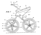
- a velocipede described with primary reference to a bicycle configuration and with further reference to a tricycle alternative is constructed as follows:
- a central unitary frame 1 is provided which may be manufactured by any known technique such as by casting or by fabrication but which is preferably manufactured by pressing left hand and right hand halves 2 and 3 respectively (Fig. 4) of the frame from sheet metal so that each half has a peripheral flange 4. The peripheral flanges are then fastened together, for example by welding, to form the central unitary frame 1 having a hollow interior.
- the central unitary frame could be constructed in other ways and from other material, for example by moulding or casting from a suitable plastics material.
- the central unitary frame has a forward portion forming a headstock 5 is which are supported bearings 6 and 7 arranged to rotatably support a spindle 8.
- the bearing 6 may, for example, be a plain bearing to damp the steering due to inherent friction and the bearing 7 may be a cone bearing arranged to support the weight of the bicycle.
- the spindle may be located in the bearings by a clamp 9 located immediately above the plain bearing 6.
- the bicycle is provided with handle bars 10 in the form of a tube 11 fastened to and extending upwardly from the spindle 8 and then curved forwardly to terminate in an upper end 12 to which is fastened a transverse member 13 to form T-shaped handle bars.
- the handle bars may be provided with a hand brake actuator 14 to actuate cable operated brakes on the bicycle.
- the spindle 8 engages the externally knurled lower end of the tube 11.
- the lower cone bearing 7 is pressed onto the spindle 8 which is flared outwardly at its lower end 15.
- a cap 40 is provided which engages with the cone bearing and also assists in holding the two halves of the frame 1 together.
- the bearing self-aligns and tightens when weight is placed on the bicycle.
- the clamp 9, which prevents the handle bars from dropping when the bicycle is lifted by the frame or seat, can be adjusted to take up slack in the system or to lower the cone bearing for lubrication.
- the lower end 15 of the spindle is flared outwardly and tubes 16 are welded to either side of the outwardly flared portion to form the front forks of the bicycle.
- the front forks are provided with an axle 17 supporting the front wheel 18 which may, for example be a conventional spoked bicycle wheel having a pneumatic tyre.
- the wheels are formed from a nylon reinforced plastics material, provided with a pneumatic tyre 19 in the conventional manner.
- the front wheel is provided with pedal cranks 20 and pedals 21 which may be rigidly secured to the axle 17 or alternatively may be arranged to drive the front wheel through a ratchet mechanism providing a free wheeling effect for ease of riding the bicycle.
- the direct drive so provided is suitable for some low speed industrial or "off-road” situations, but for other uses the bicycle is provided with an integral overdrive planetary gearbox incorporated within the hub 22 of the front wheel.
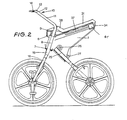
- the bicycle is provided with rear forks 23 comprising two tubes welded either side of a central tube 25 which is housed within the lower part of the central unitary frame 1.
- the tube 25 is held in place by friction achieved by tightening pinch bolts 26 and 27 to tighten the sides 2 and 3 of the central unitary frame about the tube 25 and hold it firmly in place.
- the rear forks are cantilevered downwardly and rearwardly from the headstock area 5 in a substantially straight line intersecting with the spindle 8 of the headstock.
- a rear wheel 28 is provided mounted in suitable bearings on an axle 29 supported in the rear forks 23 and is provided with a pneumatic tyre 30 in a similar manner to the front wheel.
- the bicycle is kept to a very compact overall dimension by using wheel sizes which are smaller than those commonly used on bicycles.
- the wheels are approximately 500 mm (20") in diameter. Larger wheels could, of course, be used but it is not envisaged that a bicycle of this configuration would have wheels larger than 600 mm (24") in diameter.
- the wheel base of the bicycle is able to be kept very short due to the configuration of the bicycle and it is not envisaged that the wheel base would exceed 900 mm (36").
- the wheel base of the bicycle is less than 750 mm (30") and preferably of the order of 625 to 700 mm.
- the bicycle is provided with an elongate seat 31 mounted on top of the unitary frame 1 and cantilevered rearwardly and upwardly from the headstock 5.
- the seal may be formed of any suitable material but is preferably mounted from a self-skinning plastics foam forming a compressible outer layer 32 about a plastics inner shell 33.
- the plastics inner shell is provided with a hinged end at the rear 34 to provide access to a tool box compartment 41.
- the seat is mounted on the unitary frame as a force fit so that inwardly protruding flanges 36 in either side of the seat engage with corresponding inwardly formed ribs 37 in the central frame to hold the seat firmly in place.
- the forward portion 38 of the seat is raised upwardly and continued forwards around the handle bar rod 11 to provide protection for the rider in the event of a collision.
- the seat is inclined to the horizontal at as angle of between 5° and 25° and preferably at an angle of approximately 15°. Because of the elongate and angled nature of the seat; it is possible for riders of different sizes to use the bicycle without making any adjustments to the frame and yet to be placed in the ideal ergonomic position for operation of the pedals and handle bars.
- the rider is lower to the ground than on a conventional bicycle which assists in maintaining balance and steadying the bicycle when at rest.
- the seat 31 may be made sufficiently long to support a pillion rider on the rear end of the seat.
- a clear open space 39 is left above the rear wheel and behind and below the seat 31.
- This space may be utilised by mounting a load carrying tray or luggage rack above the rear wheel.
- the container is located directely over the rear wheel and fairly low to the ground due to the small diameter of the wheel, a large load may be carried without upsetting the balance of the bicycle or making the bicycle difficult to ride.
- the thighs of the rider extend forwardly from the seat 31 and do not cross the open space 39. This allows the luggage rack or container to be much wider than the bicycle without fouling the legs of the rider and so permits a larger load to be carried.
- the rear forks and rear wheel assembly may be quickly and conveniently removed from the central unitary frame by loosening the pinch bolts 26 and 27.
- the rear assembly may be replaced by a rear frame supporting two rear wheels side by side and resulting in a tricycle configuration.
- the rear frame may be a simple T-shaped from having a central stalk tube fitted into the central unitary frame in place of the tube 25 and terminating in a hori- .zontal head tube axle having the two rear wheels located at either end.
- the rear frame may comprise a tube insertable into the unitary frame as before but of shortened length and terminating in a T-head tube extending across the end of the central tube and then being turned downwardly and rearwardly at each end to form locating points for individual axles for each rear wheel.
- This configuration has the advantage that there is no continuous axles between the two rear wheels and enables a large load carrying container to be mounted between the rear wheels for carrying a load of considerable size and weight. It is envisaged that the tricycle configuration has many applications both in industrial situations where it can be used for the simple transportation of goods or components from place to place within an industrial complex, and also in underdeveloped countries as a viable alternative form of man- powered transportation for transporting people and goods.
- Both the bicycle and tricycle configuration are particularly suitable for use in underdeveloped countries as all the components are particularly simple and rubust requiring little maintenance and having an expected long life.
- the construction is also very economical compared ' with conventional bicycles as the components are all simple and easy to manufacture, and the amount of material used is kept to a minimum due to the compact size and configuration of the bicycle.
Landscapes
- Engineering & Computer Science (AREA)
- Mechanical Engineering (AREA)
- Steering Devices For Bicycles And Motorcycles (AREA)
- Automatic Cycles, And Cycles In General (AREA)
- Materials For Medical Uses (AREA)
- Motorcycle And Bicycle Frame (AREA)
Priority Applications (1)
| Application Number | Priority Date | Filing Date | Title |
|---|---|---|---|
| AT80304100T ATE11258T1 (de) | 1979-11-15 | 1980-11-14 | Veloziped. |
Applications Claiming Priority (2)
| Application Number | Priority Date | Filing Date | Title |
|---|---|---|---|
| AUPE134079 | 1979-11-15 | ||
| AU1340/79 | 1979-11-15 |
Publications (3)
| Publication Number | Publication Date |
|---|---|
| EP0029359A2 EP0029359A2 (en) | 1981-05-27 |
| EP0029359A3 EP0029359A3 (en) | 1982-01-27 |
| EP0029359B1 true EP0029359B1 (en) | 1985-01-16 |
Family
ID=3768334
Family Applications (1)
| Application Number | Title | Priority Date | Filing Date |
|---|---|---|---|
| EP80304100A Expired EP0029359B1 (en) | 1979-11-15 | 1980-11-14 | A velocipede |
Country Status (10)
| Country | Link |
|---|---|
| US (1) | US4389055A (OSRAM) |
| EP (1) | EP0029359B1 (OSRAM) |
| JP (1) | JPS5848396B2 (OSRAM) |
| AT (1) | ATE11258T1 (OSRAM) |
| AU (1) | AU534927B2 (OSRAM) |
| CA (1) | CA1163656A (OSRAM) |
| DD (1) | DD154090A5 (OSRAM) |
| DE (1) | DE3069988D1 (OSRAM) |
| NZ (1) | NZ195510A (OSRAM) |
| PL (1) | PL227880A1 (OSRAM) |
Cited By (1)
| Publication number | Priority date | Publication date | Assignee | Title |
|---|---|---|---|---|
| DE19736266C2 (de) * | 1997-08-15 | 1999-07-08 | Thomas Dipl Ing Kretschmer | Liegefahrrad mit Vorderradantrieb |
Families Citing this family (16)
| Publication number | Priority date | Publication date | Assignee | Title |
|---|---|---|---|---|
| NL1007924C2 (nl) * | 1997-12-29 | 1999-06-30 | Langenberg Bv | Twee- of driewielig voertuig. |
| US4666172A (en) * | 1986-04-07 | 1987-05-19 | Hartmann Dirck T | Multiple speed planetary transmission for pedal-powered vehicles |
| US4706982A (en) * | 1986-04-21 | 1987-11-17 | Hartmann Dirck T | Dual range planetary transmission for pedal powered vehicles |
| US4721015A (en) * | 1986-09-08 | 1988-01-26 | Hartmann Dirck T | Three stage planetary driving wheel for pedal powered vehicles |
| GB8719384D0 (en) * | 1987-08-19 | 1987-09-23 | Bullen P G | Three in one fun bike |
| GB2232390B (en) * | 1989-05-31 | 1993-08-18 | Wang Fu Chao | Foldable multipurpose bicycle |
| US5129665A (en) * | 1990-11-21 | 1992-07-14 | Roadmaster Corporation | Bicycle frame with one or two improved wishbone stays |
| EP0910531B1 (de) * | 1996-07-09 | 1999-12-29 | GRIMM, Friedrich | Einspuriges zweirad |
| DE19824745A1 (de) * | 1998-06-03 | 1999-12-09 | Thomas Kretschmer | Farradnabe mit Mehrgangschaltung und integrierter Tretachse |
| USD496885S1 (en) | 2003-07-29 | 2004-10-05 | Eric Noble | Motorized cycle |
| JP2006137410A (ja) * | 2004-10-18 | 2006-06-01 | Radio Flyer Inc | 変換式乗用玩具 |
| US20080048412A1 (en) * | 2006-08-22 | 2008-02-28 | A.T.D. - Airwalking Technologies & Development Ltd. | Pedal-Powered Vehicle |
| NZ569837A (en) * | 2008-07-17 | 2011-06-30 | Projectgarlic Ltd | A collapsible cycle with wheels of different diameter, one of the wheels having a recess capable of accepting the other wheel |
| DE102011122836B4 (de) | 2011-10-17 | 2013-07-25 | Karsten Bettin | Kompaktes, zusammenklappbares Fahrrad |
| WO2015035095A1 (en) * | 2013-09-04 | 2015-03-12 | Helical Robotics, Llc | Three-wheeled mobile robot |
| WO2017046856A1 (ja) * | 2015-09-14 | 2017-03-23 | 有限会社 デザイン・アンリミテッド | 折りたたみ二輪車 |
Family Cites Families (9)
| Publication number | Priority date | Publication date | Assignee | Title |
|---|---|---|---|---|
| US185401A (en) * | 1876-12-19 | Improvement in velocipedes | ||
| US385258A (en) * | 1888-06-26 | Velocipede | ||
| US1476732A (en) * | 1922-05-10 | 1923-12-11 | Smith Mfg Co Inc | Article of manufacture |
| US1772231A (en) * | 1928-06-12 | 1930-08-05 | John R Smith | Child's bicycle |
| US2244709A (en) * | 1938-11-15 | 1941-06-10 | Electro Metallurg Co | Vehicle |
| US3377084A (en) * | 1966-05-12 | 1968-04-09 | M T & D Company | Seat for velocipede |
| FR2256070A1 (en) * | 1973-12-28 | 1975-07-25 | Sahuc Auguste | Folding tricycle for child - has handlebar and wheel portion swinging into horiz. position on saddle |
| FR2335393A1 (fr) * | 1975-12-15 | 1977-07-15 | Grammatico Roger | Perfectionnements apportes a une bicyclette a propulsion brachiale |
| DE2804993A1 (de) * | 1977-02-16 | 1978-08-17 | Ampaglas Spa | Klappfahrrad |
-
1979
- 1979-11-15 AU AU64249/80A patent/AU534927B2/en not_active Ceased
-
1980
- 1980-11-07 US US06/205,050 patent/US4389055A/en not_active Expired - Lifetime
- 1980-11-10 NZ NZ195510A patent/NZ195510A/en unknown
- 1980-11-13 CA CA000364545A patent/CA1163656A/en not_active Expired
- 1980-11-14 AT AT80304100T patent/ATE11258T1/de not_active IP Right Cessation
- 1980-11-14 DE DE8080304100T patent/DE3069988D1/de not_active Expired
- 1980-11-14 EP EP80304100A patent/EP0029359B1/en not_active Expired
- 1980-11-15 PL PL22788080A patent/PL227880A1/xx unknown
- 1980-11-15 JP JP55161319A patent/JPS5848396B2/ja not_active Expired
- 1980-11-17 DD DD80225268A patent/DD154090A5/de unknown
Cited By (1)
| Publication number | Priority date | Publication date | Assignee | Title |
|---|---|---|---|---|
| DE19736266C2 (de) * | 1997-08-15 | 1999-07-08 | Thomas Dipl Ing Kretschmer | Liegefahrrad mit Vorderradantrieb |
Also Published As
| Publication number | Publication date |
|---|---|
| JPS5686875A (en) | 1981-07-15 |
| PL227880A1 (OSRAM) | 1981-08-07 |
| US4389055A (en) | 1983-06-21 |
| ATE11258T1 (de) | 1985-02-15 |
| EP0029359A2 (en) | 1981-05-27 |
| NZ195510A (en) | 1984-05-31 |
| JPS5848396B2 (ja) | 1983-10-28 |
| CA1163656A (en) | 1984-03-13 |
| DD154090A5 (de) | 1982-02-24 |
| AU534927B2 (en) | 1984-02-23 |
| DE3069988D1 (en) | 1985-02-28 |
| AU6424980A (en) | 1981-07-16 |
| EP0029359A3 (en) | 1982-01-27 |
Similar Documents
| Publication | Publication Date | Title |
|---|---|---|
| EP0029359B1 (en) | A velocipede | |
| US4079957A (en) | Convertible tricycle | |
| US5072961A (en) | Bicycle with universal adjustable frame | |
| US4373740A (en) | Three-wheel vehicle | |
| US5470089A (en) | Scooter | |
| US5067738A (en) | Child powered bicycle trailer | |
| US4917396A (en) | Tricycle | |
| US3193305A (en) | Front wheel drive for bicycles | |
| US4368897A (en) | Bicycle frame structure | |
| US3834721A (en) | Twin chain drive for tricycles | |
| US8157279B2 (en) | Trailing cycle | |
| US5620196A (en) | Recumbent bicycle frame | |
| US3997185A (en) | Bicycle frame | |
| US11142274B1 (en) | Recumbent bicycle and methods of riding employing supplemental upper body power, enhanced aerodynamics, stability, and control | |
| US9278723B2 (en) | Recumbent vehicle | |
| US5133569A (en) | Training wheel assembly for bicycle | |
| EP2147852A1 (en) | Recumbent Tricycle | |
| US3866945A (en) | Recreational vehicle | |
| US5342074A (en) | Dual recumbent vehicle | |
| US3913946A (en) | Rear wheel drive for a tricycle | |
| US3371944A (en) | Variable axis center wheel | |
| US3724873A (en) | Three-wheeled vehicle | |
| US6409195B1 (en) | Handcranked rear-wheel axle-driven sport wheelchair | |
| US2815222A (en) | Tricycle driving and braking arrangement | |
| JPH11180369A (ja) | 多機能自転車 |
Legal Events
| Date | Code | Title | Description |
|---|---|---|---|
| PUAI | Public reference made under article 153(3) epc to a published international application that has entered the european phase |
Free format text: ORIGINAL CODE: 0009012 |
|
| AK | Designated contracting states |
Designated state(s): AT BE CH DE FR GB IT LU NL SE |
|
| PUAL | Search report despatched |
Free format text: ORIGINAL CODE: 0009013 |
|
| AK | Designated contracting states |
Designated state(s): AT BE CH DE FR GB IT LU NL SE |
|
| 17P | Request for examination filed |
Effective date: 19820517 |
|
| ITF | It: translation for a ep patent filed | ||
| GRAA | (expected) grant |
Free format text: ORIGINAL CODE: 0009210 |
|
| AK | Designated contracting states |
Designated state(s): AT BE CH DE FR GB IT LI LU NL SE |
|
| REF | Corresponds to: |
Ref document number: 11258 Country of ref document: AT Date of ref document: 19850215 Kind code of ref document: T |
|
| REF | Corresponds to: |
Ref document number: 3069988 Country of ref document: DE Date of ref document: 19850228 |
|
| ET | Fr: translation filed | ||
| PLBE | No opposition filed within time limit |
Free format text: ORIGINAL CODE: 0009261 |
|
| STAA | Information on the status of an ep patent application or granted ep patent |
Free format text: STATUS: NO OPPOSITION FILED WITHIN TIME LIMIT |
|
| PG25 | Lapsed in a contracting state [announced via postgrant information from national office to epo] |
Ref country code: LU Free format text: LAPSE BECAUSE OF NON-PAYMENT OF DUE FEES Effective date: 19851130 |
|
| 26N | No opposition filed | ||
| PGFP | Annual fee paid to national office [announced via postgrant information from national office to epo] |
Ref country code: AT Payment date: 19861112 Year of fee payment: 7 |
|
| PGFP | Annual fee paid to national office [announced via postgrant information from national office to epo] |
Ref country code: NL Payment date: 19861130 Year of fee payment: 7 |
|
| PG25 | Lapsed in a contracting state [announced via postgrant information from national office to epo] |
Ref country code: AT Effective date: 19871114 |
|
| PG25 | Lapsed in a contracting state [announced via postgrant information from national office to epo] |
Ref country code: SE Effective date: 19871115 |
|
| PG25 | Lapsed in a contracting state [announced via postgrant information from national office to epo] |
Ref country code: LI Effective date: 19871130 Ref country code: CH Effective date: 19871130 Ref country code: BE Effective date: 19871130 |
|
| BERE | Be: lapsed |
Owner name: ACROW PTY. LTD Effective date: 19871130 |
|
| PG25 | Lapsed in a contracting state [announced via postgrant information from national office to epo] |
Ref country code: NL Effective date: 19880601 |
|
| NLV4 | Nl: lapsed or anulled due to non-payment of the annual fee | ||
| GBPC | Gb: european patent ceased through non-payment of renewal fee | ||
| PG25 | Lapsed in a contracting state [announced via postgrant information from national office to epo] |
Ref country code: FR Free format text: LAPSE BECAUSE OF NON-PAYMENT OF DUE FEES Effective date: 19880729 |
|
| REG | Reference to a national code |
Ref country code: CH Ref legal event code: PL |
|
| PG25 | Lapsed in a contracting state [announced via postgrant information from national office to epo] |
Ref country code: DE Effective date: 19880802 |
|
| REG | Reference to a national code |
Ref country code: FR Ref legal event code: ST |
|
| PG25 | Lapsed in a contracting state [announced via postgrant information from national office to epo] |
Ref country code: GB Effective date: 19881118 |
|
| EUG | Se: european patent has lapsed |
Ref document number: 80304100.3 Effective date: 19880913 |