EP0029348A2 - Metal printing screen for flat screen printing - Google Patents
Metal printing screen for flat screen printing Download PDFInfo
- Publication number
- EP0029348A2 EP0029348A2 EP80304067A EP80304067A EP0029348A2 EP 0029348 A2 EP0029348 A2 EP 0029348A2 EP 80304067 A EP80304067 A EP 80304067A EP 80304067 A EP80304067 A EP 80304067A EP 0029348 A2 EP0029348 A2 EP 0029348A2
- Authority
- EP
- European Patent Office
- Prior art keywords
- printing
- screen
- former
- metal
- printing screen
- Prior art date
- Legal status (The legal status is an assumption and is not a legal conclusion. Google has not performed a legal analysis and makes no representation as to the accuracy of the status listed.)
- Granted
Links
Images


Classifications
-
- B—PERFORMING OPERATIONS; TRANSPORTING
- B41—PRINTING; LINING MACHINES; TYPEWRITERS; STAMPS
- B41F—PRINTING MACHINES OR PRESSES
- B41F15/00—Screen printers
- B41F15/14—Details
- B41F15/34—Screens, Frames; Holders therefor
- B41F15/36—Screens, Frames; Holders therefor flat
-
- B—PERFORMING OPERATIONS; TRANSPORTING
- B41—PRINTING; LINING MACHINES; TYPEWRITERS; STAMPS
- B41C—PROCESSES FOR THE MANUFACTURE OR REPRODUCTION OF PRINTING SURFACES
- B41C1/00—Forme preparation
- B41C1/14—Forme preparation for stencil-printing or silk-screen printing
- B41C1/142—Forme preparation for stencil-printing or silk-screen printing using a galvanic or electroless metal deposition processing step
Definitions
- the present invention relates to a metal printing screen for flat screen printing of the type comprising of flat printing portion and an outer peripheral mounting portion integral with and extending over at least portion of the periphery of the printing portion, the mounting portion being adapted for releasable engagement with a forme frame. Additionally, the invention relates to a method and a former for manufacturing the metal printing screen as well as a printing screen forme incorporating the metal printing screen.
- the screen comprises a metal mesh of, for example, stainless steel, and a mask of photosensitive material is applied to the metal mesh.
- the mask is removed from unwanted portions of the mesh to form the printing pattern by exposing those portions of the mask to light.
- by exposing the mask using a negative of the printing pattern is substantially similar to conventional silk screens, with the exception that instead of a screen of textile fibres a metal mesh screen is used.
- the printing screen comprises a metal mesh, preferably of stainless steel and a metal mask is formed on the mesh by, for example, electrolytically depositing a metal foil onto the mesh. The printing pattern is then etched in the foil leaving portions of the mesh exposed.
- the screen comprises a metal mesh, again preferably of stainless steel, and a mask formed by a sheet of metal material, preferably of copper, is soldered to the mesh. The printing pattern is then etched from the metal mask and soldered leaving portions of the mesh exposed.
- U.S. Patent Specification No. 4084506 describes a still further type of metal printing screen.
- the metal mesh is formed on a metal plate which subsequently forms the mask.
- the metal plate is preferably of copper material and the mesh is formed by electrolytically depositing, for example, nickel on the copper plate. The printing pattern is then etched from the copper plate.
- each of these types of printing screen require a metal mesh, and in each case, the outer edges of the mesh or screen are bent upwardly to form side members to engage a forme frame.
- the side members are bent upwardly after the printing pattern has been formed.
- the printing pattern is not accurately positioned relative to the side members and consequently registration problems occur during subsequent printing. Even if the side members are formed before the printing pattern is formed, the problem of accurately positioning the printing pattern relative to the side members is still encountered.
- An object of the invention is to provide a metal printing screen for flat screen printing which will overcome these problems. It is also an object of the invention to provide a method and former for manufacturing the metal printing screen. Additionally, it is an object of the invention to provide a printing screen forme incorporating the metal printing screen.
- the printing portion and in turn the printing pattern is accurately positioned relative to the mounting portion of the printing screen. Additionally, where it is desired to form a number of printing screens from the same former, the printing screens will be similar to each other and the printing screens can readily be interchanged without registration problems during subsequent printing. Furthermore, because the entire screen is formed by electrolytic deposition, a metal mesh is not required and therefore, each of the openings which forme the printing pattern may be positioned in any desired location, thus ensuring that small details in the printing pattern will be printed, where heretofore small details in a printing pattern could be obliterated by a wire, strand or fibre forming the mesh of the printing screen.
- the mounting portion comprises an upstanding mounting member adjacent at least two opposing sides of the printing portion.
- the advantage of this embodiment of the invention is that the printing screen can readily and easily be mounted on a forme frame.
- the upstanding mounting member extends around the periphery of the printing portion.
- the advantage of this embodiment of the invention is that the screen can be adequately tensioned in all directions.
- the printing portion and the mounting pdrtion are simultaneously formed on the former.
- the advantage of this embodiment of the invention is that the mounting portion may be used for registering the printing pattern, and furthermore it enables the printing screen to be evenly tensioned in all directions leading to improved quality of printing.
- the object of the invention is also achieved in accordance with the present invention in as much as the method for manufacturing the metal printing screen comprises the steps of forming a negative of the printing portion and the mounting portion on a former, and forming the printing portion and the mounting portion by electrolytic deposition onto the former.
- the printing screen will similarly be accurately formed, thus leading to imporved quality of printing. Additionally, the printing portion of the printing screen and in turn the printing pattern are accurately positioned relative to the mounting portion.
- the mounting portion is simultaneously formed with the printing portion, the printing portion and the mounting . portion being electrolytically deposited on a corresponding forming face and corresponding side faces, respectively, of the former.
- the mounting portion may be used for registering the printing screen.
- the negative of the printing screen is engraved onto the former.
- the advantage of this embodiment of the invention is that it provides a durable former suitable for manufacturing relatively large quantities of similar printing screens.
- the invention provides a former for carrying out the method for manufacturing the metal printing screen, the former having a negative of the printing screen engraved thereon.
- the negative may be engraved by mechanical engraving or it could be etched by acid or electrolytic means.
- the advantage of this embodiment of the invention is that the former is durable and a relatively large number of similar printing screens can be produced from the same former. Further, the invention privides a printing screen forme comprising .the printing screen mounted on a forme frame.
- a printing screen forme according to the invention indicated generally by the reference numeral 1 for flat screen printing.
- the printing screen forme comprises a printing screen 2 also accroding to the invention releasably mounted to a forme frame 3.
- the forme frame 3 is made up of four timber sections 4 adjustable outwardly so that the printing screen 2 may be tensioned onto the frame 3.
- Locking screws 6 are provided to lock the frame 3 in position when the screen 2 is suitably tensioned.
- Fixing holes 7 are provided in the frame 3 to engage pegs 8 for securing the screen 2 to the frame 3.
- the printing screen 2 comprises a printing portion 9 in'which is formed a printing pattern 10, and a mounting portion, provided by upstanding side mounting members 11 around the periphery of the printing portion 9.
- the printing portion 9 and the side members 11 are of nickel material and are formed simultaneously by electrolytic deposition of nickel onto a former as will be described in detail below.
- the side members 11 embrace the forme frame 3, and fixing holes 12 in the side members 11 are provided to engage the pegs 8.
- the printing pattern on the screen 2 comprises a large square formed by boundary lines 20 and having a shaded portion 21 at opposing corners of the large square.
- a small rectangle shaded portion 22 is provided in the centre of the large square.
- a detail of portion of the printing pattern is shown in Fig. 3 and it can be seen that the lines 20 are each formed by a plurality of openings 24, while the shaded portions 1 are also formed by a plurality of openings 25 forming a grid pattern to accomodate the passage of printing ink.
- Figs. 4 and 5 show a former 15 on which the printing screen 2 is formed by electrolytic deposition.
- the former 15 is of brass material and comprises a forming face 16 on which the printing portion 9 of the screen 2 is formed and side faces 17 on which the side members 11 are formed.
- a negative 18 of the printing pattern 10 of the screen 2 is engraved into the forming face 16.
- the negative 18 includes a plurality of openings 26 and 27 corresponding to the openings 24 and 25 on the printing screen 2 engraved into the forming face 16 of the former 15, see-Fig. 5. Accordingly, when the screen is being formed on the former 15 the openings 26 and 27 form the openings 24 and 25 in the screen 2. Similarly, holes 28 engraved into the side faces 17 form the fixing holes 12 in the printing screen 2.
- the former 15 is immersed in a nickel plating solution (not shown) and acts as a cathode. Electric current passed through nickel anodes (also not shown) in the solution and the former 15 causes nickel to be deposited onto the forming face 16 and side faces 17 of the former 15, thus forming the printing screen 2. Nickel is not deposited over the openings 26 and 27 and the holes 28, thereby forming the openings 24 and 25 and the holes 12 in the printing screen 2.
- the printing screen 2 is then seperated from the former and mounted on the forme frame 3 by the pegs 8.
- the frame 3 is extended outwardly by means of the expandable joints 5 to tension the printing portion 9 over the frame 3.
- the locking screws 6 are tightened and the printing forme 1 is used in conventional manner.
- the printing pattern 10 is always accurately positioned relative to the side members 11. This is mainly because the side faces 17 of the former can be accurately machined and in turn the side members are accurately formed.
- each of the openings forming the grid pattern can be positioned in any desired location by merely providing a hole or opening in the forming face 16 of the former 15.
- an opening or hole corresponding to the detail can be provided on the forming face 16 of the former 15.
- Figs. 6 and 7 show a former 15 according to another embodiment of the invention.
- This former 15 is essentially similar to the former 15 described with reference to Figs. 4 and 5, and like parts are identified by the same reference numerals.
- the negative 18 is formed by a deposit of electro-resist material on the forming face 16 and the side faces 17 of the former 16.
- the deposits of electro-resist material correspond to openings in the printing screen and prevent nickel being formed on the former at those positions.
- a plurality of , circular deposits 45 of electro-resist material correspond to the opening 24 which form the lines 20 in the printing screen 2.
- circular deposits 46 of electro-resist material correspond to the openings 25 in the printing screen 2 which form the shaded area'21.
- Circular deposits 47 of electro-resist material on the side faces 17 of the former correspond to fixing holes 12 of the printing screen 2.
- a coating of a negative working photo-resist material having electro-resist properties is applied to the forming face 16 and the side faces 17 of the former 15. Needless to say, if desired a coating of positive working photo-resist material could be applied instead.
- the faces 16 and 17 are then negatively exposed using a negative of the printing pattern, and are subsequently developed. The portions exposed to light are hardened and form the deposits of electro-resist material, and the areas of the coating which have not been exposed are washed off.
- the printing screen 2 is then formed on the former 15 as already described with reference to Figs 4 and 5.
- the portions of the forming face covered by the electro-resist material prevent nickel being deposited on these areas, which in turn form the openings in the printing pattern.
- the apparatus includes a printing forme substantially similar to that described with reference to Figs. 1 to 3 and like components are identified by the same reference numerals.
- the apparatus includes a printing table, the top portion 30 of which is shown.
- the medium on which the pattern is printed, in this embodiment of the invention, a sheet 31 of textile material is placed on the top 30 of the table.
- the printing screen 2 is of nickel material again formed by electrolytic deposition onto a former (not shown).
- the printing screen 2 includes registering means provided by a pair of register holes 29 outside the printing pattern.
- the registered holes are formed during the electrolytic forming process by corresponding holes in the forming face of the former, thus ensuring accurate positioning of the register holes.
- Alignment means provided by pins 32 project from the printing table 30 to engage the register holes 29, so that the printing pattern 10 can be readily and easily aligned with the sheet 31. Therefore, when it is desired to print a multi-coloured pattern and a number of printing screens are used with corresponding register holes 29, registration of the printed pattern for each of the , colours is readily and easily assured.
- the register holes 29 could be used to print dots onto the sheet 31, and the register holes 29 of subsequent screens could be then aligned with the dots.
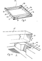
- Figs. 9 and 10 show a printing forme according to another embodiment of the invention.
- the printing forme is substantially similar to that described with reference to Figs. 1 to 3 and accordingly, like components are identified by the same reference numerals.
- the printing screen 2 of nickel material has only two side mounting members 11.
- the side members 11 are bent upwardly into position after the printing screen has been formed by electrolytic deposition on a flat forming face of a former (not shown).
- Lips 35 ' to engage the frame 3 are formed on the side members 11 by bending the top portion of the side members inwardly.
- a plurality of pegs or nails 8 secure the lips 35 to the frame 3.
- the frame 3 comprises a pair of outwardly adjustable side members 36 and transverse members 37 which engage recesses 38 in the side members 37. It can be seen in Fig. 10 that ends 39 of the transverse members 37 are inclined downwardly. Inner faces 40 of the recesses 38 are correspondingly inclined, so that by pressing the transverse members 37 downwardly into the recesses 38 in the direction of the arrow A (see Fig. 10) a wedging action is achieved, forcing the side members 36 outwardly to tension the screen 2.
- any of the printing screens may be formed on a flat face of a former with the printing portion, and the side members can subsequently be formed by bending the mounting portion upwardly as described with reference to the embodiment of the invention of Figs. 9 and 10, without departing from the scope of the invention.
- the side mounting members could be provided by a tab on opposing sides of the printing portion if desired.
- the mounting portion could be in the same plane as the printing portion, and the mounting portion could be secured to the underside of the forme frame by gluing, nailing or the like.
- the printing screen has been described as being formed from nickel material, other suitable metals could have been used. It will also be appreciated that a former of a material other than copper could have been used. Similarly, it will be appreciated that materials other than timber could have been used in the forme frame, for example, plastics material or metal.
- a metal forme frame may be provided.
- the outer dimensions of the forme frame would be machined to correspond to those of the former. This would ensure that the printing screen and the forme frame would be an accurate fit with each other. It is also envisaged that this forme frame could be made adjustable or colapsable to facilate fitting or removal of the screen to or from the forme frame.
- the printing screen could be formed with its' upstanding side mounting members inwardly inclined to facilitate fixing to the forme frame.
- the side faces of the former would be correspondingly inclined and a forme frame with similarily inclined sides would also be provided.
- fixing means other than those described to secure the printing screen to the forme frame could be used.
- a printing screen with printing patterns other than those described could be manufactured.
- the printing pattern it is not necessary that the printing pattern be restricted to geometric shapes, printing patterns including images of people, landscapes and the like could be manufactured according to the invention, and washed colours.could, for example, be obtained by varying the spacing and diameter of the openings in the printing pattern of the printing screen.
- the printing screen could be used for printing on many other media, for example, on paper and cardboard, for example, in packaging cartons and the like, or on pottery. Indeed, it is also envisaged that the printing screen could be used in the printing of printed circuit boards.
- a sealing member for example, an o-ring seal. may be fitted between the printing screen and the bottom portion of the forme frame to prevent the ingress of printing ink or paint between the screen and the forme frame.
Landscapes
- Engineering & Computer Science (AREA)
- Manufacturing & Machinery (AREA)
- Mechanical Engineering (AREA)
- Printing Plates And Materials Therefor (AREA)
- Screen Printers (AREA)
Abstract
Description
- The present invention relates to a metal printing screen for flat screen printing of the type comprising of flat printing portion and an outer peripheral mounting portion integral with and extending over at least portion of the periphery of the printing portion, the mounting portion being adapted for releasable engagement with a forme frame. Additionally, the invention relates to a method and a former for manufacturing the metal printing screen as well as a printing screen forme incorporating the metal printing screen.
- There are a number of known types of metal printing screens for flat screen printing. For example, in one type the screen comprises a metal mesh of, for example, stainless steel, and a mask of photosensitive material is applied to the metal mesh. The mask is removed from unwanted portions of the mesh to form the printing pattern by exposing those portions of the mask to light. In other-words, by exposing the mask using a negative of the printing pattern. This type of screen is substantially similar to conventional silk screens, with the exception that instead of a screen of textile fibres a metal mesh screen is used.
- Another type of metal printing screen is described in British Patent Specification No. 1393056. In this type, the printing screen comprises a metal mesh, preferably of stainless steel and a metal mask is formed on the mesh by, for example, electrolytically depositing a metal foil onto the mesh. The printing pattern is then etched in the foil leaving portions of the mesh exposed.
- A further type of metal printing screen is described in U.S. Patent Specification 2421607. In this type, the screen comprises a metal mesh, again preferably of stainless steel, and a mask formed by a sheet of metal material, preferably of copper, is soldered to the mesh. The printing pattern is then etched from the metal mask and soldered leaving portions of the mesh exposed.
- U.S. Patent Specification No. 4084506 describes a still further type of metal printing screen. In this printing screen the metal mesh is formed on a metal plate which subsequently forms the mask. The metal plate is preferably of copper material and the mesh is formed by electrolytically depositing, for example, nickel on the copper plate. The printing pattern is then etched from the copper plate.
- However, each of these types of printing screen require a metal mesh, and in each case, the outer edges of the mesh or screen are bent upwardly to form side members to engage a forme frame. In general, the side members are bent upwardly after the printing pattern has been formed. Unfortunately, without relatively complex and expensive apparatus, it is virtually impossible to ensure that the sides are bent accurately. Accordingly, the printing pattern is not accurately positioned relative to the side members and consequently registration problems occur during subsequent printing. Even if the side members are formed before the printing pattern is formed, the problem of accurately positioning the printing pattern relative to the side members is still encountered.
- Furthermore, because of the difficulty of accurately forming the side members, in general, it is not possible to adequately tension the screen onto the forme frame. This, needless to say, leads to poor quality of subsequent printing.
- Additionally, in known printing screens, because mesh material is used and the mesh extends across the openings in the printing pattern, the clarity and definition of the subsequent print suffers. In fact, in the case of many known printing screens it is common to find saw-toothing around the edges of prints subsequently printed. Such saw-toothing is caused by the wires or strands of the mesh. Indeed, if a small detail in the printing pattern coincides with a wire or strand of the mesh, such a detail will not be printed.
- There is, therefore, a need for a metal printing screen which will overcome these problems and a printing forme incorporating the screen, as well as a method and former for manufacturing the printing screen.
- An object of the invention is to provide a metal printing screen for flat screen printing which will overcome these problems. It is also an object of the invention to provide a method and former for manufacturing the metal printing screen. Additionally, it is an object of the invention to provide a printing screen forme incorporating the metal printing screen.
- These objects are achieved in accordance with the present invention in as much as the printing portion and the mounting portion of the printing screen are formed by electrolytic deposition onto a former.
- The advantages achieved by the invention are that the printing portion and in turn the printing pattern is accurately positioned relative to the mounting portion of the printing screen. Additionally, where it is desired to form a number of printing screens from the same former, the printing screens will be similar to each other and the printing screens can readily be interchanged without registration problems during subsequent printing. Furthermore, because the entire screen is formed by electrolytic deposition, a metal mesh is not required and therefore, each of the openings which forme the printing pattern may be positioned in any desired location, thus ensuring that small details in the printing pattern will be printed, where heretofore small details in a printing pattern could be obliterated by a wire, strand or fibre forming the mesh of the printing screen.
- In one embodiment of the invention the mounting portion comprises an upstanding mounting member adjacent at least two opposing sides of the printing portion.
- The advantage of this embodiment of the invention is that the printing screen can readily and easily be mounted on a forme frame.
- Preferably, the upstanding mounting member extends around the periphery of the printing portion.
- The advantage of this embodiment of the invention is that the screen can be adequately tensioned in all directions.
- Advantageously, the printing portion and the mounting pdrtion are simultaneously formed on the former.
- The advantage of this embodiment of the invention is that the mounting portion may be used for registering the printing pattern, and furthermore it enables the printing screen to be evenly tensioned in all directions leading to improved quality of printing.
- The object of the invention is also achieved in accordance with the present invention in as much as the method for manufacturing the metal printing screen comprises the steps of forming a negative of the printing portion and the mounting portion on a former, and forming the printing portion and the mounting portion by electrolytic deposition onto the former.
- The advantage of this is that provided the negative on the former is accurately formed, the printing screen will similarly be accurately formed, thus leading to imporved quality of printing. Additionally, the printing portion of the printing screen and in turn the printing pattern are accurately positioned relative to the mounting portion.
- Preferably, the mounting portion is simultaneously formed with the printing portion, the printing portion and the mounting . portion being electrolytically deposited on a corresponding forming face and corresponding side faces, respectively, of the former.
- The advantage of this embodiment of the invention is that provided that the side faces of the former are accurately machined relative to the forming face, the mounting portion may be used for registering the printing screen.
- In one embodiment of the invention the negative of the printing screen is engraved onto the former.
- The advantage of this embodiment of the invention is that it provides a durable former suitable for manufacturing relatively large quantities of similar printing screens.
- The above objects are also achieved in that the invention provides a former for carrying out the method for manufacturing the metal printing screen, the former having a negative of the printing screen engraved thereon. For example, the negative may be engraved by mechanical engraving or it could be etched by acid or electrolytic means.
- The advantage of this embodiment of the invention is that the former is durable and a relatively large number of similar printing screens can be produced from the same former. Further, the invention privides a printing screen forme comprising .the printing screen mounted on a forme frame.
- The invention will be more clearly understood form the following description of some prefered embodiments thereof given by way of example only with reference to the accompanying drawings, in which:
- Fig. 1 is a perspective view of a printing screen forme incorporating a printing screen according to the invention;
- Fig. 2 is an exploded view of the printing screen forme of Fig. 1;
- Fig. 3 is a detailed view of portion of the printing screen of Fig. 1;
- Fig. 4 is a perspective view of a former according to the invention for manufacturing the printing screen of Fig. 1;
- Fig. 5 is a'detailed view showing portion of the former of Fig. 4;
- Fig. 6 is a view similar to Fig. 4 of a former according to an outer embodiment of the invention;
- Fig. 7 is a view similar to Fig. 5 of the former of Fig. 6;
- Fig. 8 is a perspective view of portion of apparatus for screen printing incorporating a printing screen forme according to another embodiment of the invention;
- Fig. 9 is a perspective view of a printing screen forme frame according to a further embodiment of the invention, and
- Fig. 10 is a detail of portion of the forme frame of Fig. 9.
- Referring to the drawings and initally to Figs. 1 to 3, there is provided a printing screen forme according to the invention, indicated generally by the
reference numeral 1 for flat screen printing. The printing screen forme comprises aprinting screen 2 also accroding to the invention releasably mounted to aforme frame 3. - The
forme frame 3 is made up of fourtimber sections 4 adjustable outwardly so that theprinting screen 2 may be tensioned onto theframe 3. Lockingscrews 6 are provided to lock theframe 3 in position when thescreen 2 is suitably tensioned. Fixing holes 7 are provided in theframe 3 to engagepegs 8 for securing thescreen 2 to theframe 3. - The
printing screen 2 comprises aprinting portion 9 in'which is formed aprinting pattern 10, and a mounting portion, provided by upstandingside mounting members 11 around the periphery of theprinting portion 9. Theprinting portion 9 and theside members 11 are of nickel material and are formed simultaneously by electrolytic deposition of nickel onto a former as will be described in detail below. Theside members 11 embrace theforme frame 3, and fixingholes 12 in theside members 11 are provided to engage thepegs 8. - In this embodiment of the invention it can be seen that the printing pattern on the
screen 2 comprises a large square formed byboundary lines 20 and having a shadedportion 21 at opposing corners of the large square. A small rectangle shadedportion 22 is provided in the centre of the large square. A detail of portion of the printing pattern is shown in Fig. 3 and it can be seen that thelines 20 are each formed by a plurality ofopenings 24, while theshaded portions 1 are also formed by a plurality ofopenings 25 forming a grid pattern to accomodate the passage of printing ink. - Figs. 4 and 5 show a former 15 on which the
printing screen 2 is formed by electrolytic deposition. The former 15 is of brass material and comprises a formingface 16 on which theprinting portion 9 of thescreen 2 is formed and side faces 17 on which theside members 11 are formed. A negative 18 of theprinting pattern 10 of thescreen 2 is engraved into the formingface 16. The negative 18 includes a plurality ofopenings openings printing screen 2 engraved into the formingface 16 of the former 15, see-Fig. 5. Accordingly, when the screen is being formed on the former 15 theopenings openings screen 2. Similarly, holes 28 engraved into the side faces 17 form the fixing holes 12 in theprinting screen 2. - To manufacture the
printing screen 2, the former 15 is immersed in a nickel plating solution (not shown) and acts as a cathode. Electric current passed through nickel anodes (also not shown) in the solution and the former 15 causes nickel to be deposited onto the formingface 16 and side faces 17 of the former 15, thus forming theprinting screen 2. Nickel is not deposited over theopenings holes 28, thereby forming theopenings holes 12 in theprinting screen 2. - The
printing screen 2 is then seperated from the former and mounted on theforme frame 3 by thepegs 8. Theframe 3 is extended outwardly by means of theexpandable joints 5 to tension theprinting portion 9 over theframe 3. When the desired tension is obtained the locking screws 6 are tightened and theprinting forme 1 is used in conventional manner. - It has been found that because the
side members 11 and theprinting portion 9 are formed simultaneously on the former 15, theprinting pattern 10 is always accurately positioned relative to theside members 11. This is mainly because the side faces 17 of the former can be accurately machined and in turn the side members are accurately formed. - Furthermore, it has been found that because the
side members 11 are accurately formed more even tensioning of thescreen 2 on theforme frame 3 can be achieved than could be heretofore achieved. , - It has also been found that the quality of prints obtained from the
printing screen 2 are of considerably higher quality than those heretofore obtained from known printing screens. The reason for this is that in the present printing screen a metal mesh is not required, because the grid pattern formed in the printing pattern is actually formed by the electrolytic process. Accrodingly, it will be appreciated that each of the openings forming the grid pattern can be positioned in any desired location by merely providing a hole or opening in the formingface 16 of the former 15. Thus, where a small detail is to be printed an opening or hole corresponding to the detail can be provided on the formingface 16 of the former 15. - Figs. 6 and 7 show a former 15 according to another embodiment of the invention. This former 15 is essentially similar to the former 15 described with reference to Figs. 4 and 5, and like parts are identified by the same reference numerals. In this embodiment of the invention, instead of being engraved on the former 15, the negative 18 is formed by a deposit of electro-resist material on the forming
face 16 and the side faces 17 of the former 16. The deposits of electro-resist material correspond to openings in the printing screen and prevent nickel being formed on the former at those positions. For example, a plurality of ,circular deposits 45 of electro-resist material correspond to theopening 24 which form thelines 20 in theprinting screen 2. Similarly,circular deposits 46 of electro-resist material correspond to theopenings 25 in theprinting screen 2 which form the shaded area'21.Circular deposits 47 of electro-resist material on the side faces 17 of the former correspond to fixingholes 12 of theprinting screen 2. - To form the negative 18 of electro-resist material on the former 15, a coating of a negative working photo-resist material having electro-resist properties is applied to the forming
face 16 and the side faces 17 of the former 15. Needless to say, if desired a coating of positive working photo-resist material could be applied instead. The faces 16 and 17 are then negatively exposed using a negative of the printing pattern, and are subsequently developed. The portions exposed to light are hardened and form the deposits of electro-resist material, and the areas of the coating which have not been exposed are washed off. - The
printing screen 2 is then formed on the former 15 as already described with reference to Figs 4 and 5. The portions of the forming face covered by the electro-resist material prevent nickel being deposited on these areas, which in turn form the openings in the printing pattern. - If a positive working photo-resist material is used, when this is exposed, the Tight softens the exposed resist material which is subsequently washed off, thus again leaving a negative of the printing screen on the former which forms the electro-resist.
- Referring now to Fig. 8 apparatus for flat screen printing is illustrated. The apparatus includes a printing forme substantially similar to that described with reference to Figs. 1 to 3 and like components are identified by the same reference numerals. The apparatus includes a printing table, the
top portion 30 of which is shown. The medium on which the pattern is printed, in this embodiment of the invention, asheet 31 of textile material is placed on the top 30 of the table. - In this embodiment of the invention, the
printing screen 2 is of nickel material again formed by electrolytic deposition onto a former (not shown). Theprinting screen 2 includes registering means provided by a pair of register holes 29 outside the printing pattern. The registered holes are formed during the electrolytic forming process by corresponding holes in the forming face of the former, thus ensuring accurate positioning of the register holes. Alignment means provided bypins 32 project from the printing table 30 to engage the register holes 29, so that theprinting pattern 10 can be readily and easily aligned with thesheet 31. Therefore, when it is desired to print a multi-coloured pattern and a number of printing screens are used with corresponding register holes 29, registration of the printed pattern for each of the , colours is readily and easily assured. - Needless to say, it will be appreciated that instead of using the register pins 32 the register holes 29 could be used to print dots onto the
sheet 31, and the register holes 29 of subsequent screens could be then aligned with the dots. - Figs. 9 and 10 show a printing forme according to another embodiment of the invention. The printing forme is substantially similar to that described with reference to Figs. 1 to 3 and accordingly, like components are identified by the same reference numerals. In this embodiment of the invention the
printing screen 2 of nickel material has only twoside mounting members 11. Theside members 11 are bent upwardly into position after the printing screen has been formed by electrolytic deposition on a flat forming face of a former (not shown).Lips 35 'to engage theframe 3 are formed on theside members 11 by bending the top portion of the side members inwardly. A plurality of pegs ornails 8 secure thelips 35 to theframe 3. - The
frame 3 comprises a pair of outwardlyadjustable side members 36 andtransverse members 37 which engage recesses 38 in theside members 37. It can be seen in Fig. 10 that ends 39 of thetransverse members 37 are inclined downwardly. Inner faces 40 of therecesses 38 are correspondingly inclined, so that by pressing thetransverse members 37 downwardly into therecesses 38 in the direction of the arrow A (see Fig. 10) a wedging action is achieved, forcing theside members 36 outwardly to tension thescreen 2. - It will be appreciated that the mounting portion of any of the printing screens may be formed on a flat face of a former with the printing portion, and the side members can subsequently be formed by bending the mounting portion upwardly as described with reference to the embodiment of the invention of Figs. 9 and 10, without departing from the scope of the invention.
- Furthermore, it will be appreciated that it is not necessary for the side mounting members to extend around the periphery of the printing portion nor indeed is it necessary for them to extend along a side of the printing portion, for example, the side mounting members could be provided by a tab on opposing sides of the printing portion if desired. Indeed, if desired, the mounting portion could be in the same plane as the printing portion, and the mounting portion could be secured to the underside of the forme frame by gluing, nailing or the like.
- Needless to say, it will be appreciated that while the printing screen has been described as being formed from nickel material, other suitable metals could have been used. It will also be appreciated that a former of a material other than copper could have been used. Similarly, it will be appreciated that materials other than timber could have been used in the forme frame, for example, plastics material or metal.
- Indeed it is envisaged that a metal forme frame may be provided. The outer dimensions of the forme frame would be machined to correspond to those of the former. This would ensure that the printing screen and the forme frame would be an accurate fit with each other. It is also envisaged that this forme frame could be made adjustable or colapsable to facilate fitting or removal of the screen to or from the forme frame.
- It is also envisaged that the printing screen could be formed with its' upstanding side mounting members inwardly inclined to facilitate fixing to the forme frame. In this case it is envisaged that the side faces of the former would be correspondingly inclined and a forme frame with similarily inclined sides would also be provided.
- It will be appreciated that fixing means other than those described to secure the printing screen to the forme frame could be used. Furthermore, a printing screen with printing patterns other than those described could be manufactured. Needless to say, it is not necessary that the printing pattern be restricted to geometric shapes, printing patterns including images of people, landscapes and the like could be manufactured according to the invention, and washed colours.could, for example, be obtained by varying the spacing and diameter of the openings in the printing pattern of the printing screen.
- It is further envisaged that as well as being used for printing on textile materials the printing screen could be used for printing on many other media, for example, on paper and cardboard, for example, in packaging cartons and the like, or on pottery. Indeed, it is also envisaged that the printing screen could be used in the printing of printed circuit boards.
- It is further envisaged that a sealing member, for example, an o-ring seal. may be fitted between the printing screen and the bottom portion of the forme frame to prevent the ingress of printing ink or paint between the screen and the forme frame.
Claims (11)
Applications Claiming Priority (4)
| Application Number | Priority Date | Filing Date | Title |
|---|---|---|---|
| IE219479A IE50691B1 (en) | 1979-11-15 | 1979-11-15 | A metal printing screen and a method for producing the printing screen |
| IE219479 | 1979-11-15 | ||
| IE156880 | 1980-07-28 | ||
| IE156880 | 1980-07-28 |
Publications (3)
| Publication Number | Publication Date |
|---|---|
| EP0029348A2 true EP0029348A2 (en) | 1981-05-27 |
| EP0029348A3 EP0029348A3 (en) | 1982-01-20 |
| EP0029348B1 EP0029348B1 (en) | 1984-12-12 |
Family
ID=26319123
Family Applications (1)
| Application Number | Title | Priority Date | Filing Date |
|---|---|---|---|
| EP80304067A Expired EP0029348B1 (en) | 1979-11-15 | 1980-11-13 | Metal printing screen for flat screen printing |
Country Status (3)
| Country | Link |
|---|---|
| EP (1) | EP0029348B1 (en) |
| DE (1) | DE3069809D1 (en) |
| IE (1) | IE50691B1 (en) |
Cited By (6)
| Publication number | Priority date | Publication date | Assignee | Title |
|---|---|---|---|---|
| WO1993025061A1 (en) * | 1992-06-03 | 1993-12-09 | David Godfrey Williams | Improved stencil or mask for applying solder to circuit boards and support frame therefor |
| GB2291624A (en) * | 1994-07-26 | 1996-01-31 | Micro Metallic Ltd | Improved stencil or mask |
| GB2294905A (en) * | 1994-11-05 | 1996-05-15 | Bengel & Bros Bebro | Stencil holder |
| US6119592A (en) * | 1996-07-03 | 2000-09-19 | Matsushita Electric Industrial Co., Ltd. | Apparatus for screen printing having a belt screen and locking frame |
| GB2419357A (en) * | 2004-10-20 | 2006-04-26 | Dek Int Gmbh | Mandrels for electroforming printing screens and methods of forming screens thereby. |
| US8490545B2 (en) | 2002-05-02 | 2013-07-23 | Dek Vectorguard Limited | Printing screens, frames therefor and printing screen units |
Families Citing this family (1)
| Publication number | Priority date | Publication date | Assignee | Title |
|---|---|---|---|---|
| CN110228280B (en) * | 2019-06-29 | 2021-12-10 | 山东同大印制系统有限公司 | 130T-shaped printing rotary screen, preparation method and application thereof |
Citations (4)
| Publication number | Priority date | Publication date | Assignee | Title |
|---|---|---|---|---|
| US2024087A (en) * | 1927-12-12 | 1935-12-10 | Standard Process Corp | Printing plate |
| US3482300A (en) * | 1966-10-31 | 1969-12-09 | Screen Printing Systems Inc | Printing screen and method of making same |
| US3862018A (en) * | 1971-11-12 | 1975-01-21 | Pat F Mentone | Rigidizing process for screens with aluminum frames |
| GB1393056A (en) * | 1972-08-28 | 1975-05-07 | Rca Corp | Metal mask screen for screen-printing |
-
1979
- 1979-11-15 IE IE219479A patent/IE50691B1/en not_active IP Right Cessation
-
1980
- 1980-11-13 EP EP80304067A patent/EP0029348B1/en not_active Expired
- 1980-11-13 DE DE8080304067T patent/DE3069809D1/en not_active Expired
Patent Citations (4)
| Publication number | Priority date | Publication date | Assignee | Title |
|---|---|---|---|---|
| US2024087A (en) * | 1927-12-12 | 1935-12-10 | Standard Process Corp | Printing plate |
| US3482300A (en) * | 1966-10-31 | 1969-12-09 | Screen Printing Systems Inc | Printing screen and method of making same |
| US3862018A (en) * | 1971-11-12 | 1975-01-21 | Pat F Mentone | Rigidizing process for screens with aluminum frames |
| GB1393056A (en) * | 1972-08-28 | 1975-05-07 | Rca Corp | Metal mask screen for screen-printing |
Cited By (14)
| Publication number | Priority date | Publication date | Assignee | Title |
|---|---|---|---|---|
| WO1993025061A1 (en) * | 1992-06-03 | 1993-12-09 | David Godfrey Williams | Improved stencil or mask for applying solder to circuit boards and support frame therefor |
| CN1055819C (en) * | 1992-06-03 | 2000-08-23 | 阿尔法·弗赖公司 | Improved stencil or mask for applying solder to circuit boards and support frame thereof |
| GB2291624A (en) * | 1994-07-26 | 1996-01-31 | Micro Metallic Ltd | Improved stencil or mask |
| GB2294905A (en) * | 1994-11-05 | 1996-05-15 | Bengel & Bros Bebro | Stencil holder |
| US6119592A (en) * | 1996-07-03 | 2000-09-19 | Matsushita Electric Industrial Co., Ltd. | Apparatus for screen printing having a belt screen and locking frame |
| US8490545B2 (en) | 2002-05-02 | 2013-07-23 | Dek Vectorguard Limited | Printing screens, frames therefor and printing screen units |
| US8904929B2 (en) | 2002-05-02 | 2014-12-09 | Dek Vectorguard Limited | Printing screens, frames therefor and printing screen units |
| EP2347901B2 (en) † | 2002-05-02 | 2016-03-02 | Asm Vectorguard Limited | Printing screen unit |
| US9623650B2 (en) | 2002-05-02 | 2017-04-18 | Asm Vectorguard Limited | Printing screen unit having screen and frame with interface members |
| US10081211B2 (en) | 2002-05-02 | 2018-09-25 | ASM Assembly Systems Weymouth Ltd. | Printing screens, frames therefor and printing screen units |
| WO2006043049A1 (en) | 2004-10-20 | 2006-04-27 | Dek International Gmbh | Mandrels for electroforming printing screens, and electroforming apparatus |
| CN101107125A (en) * | 2004-10-20 | 2008-01-16 | Dek国际有限责任公司 | Mandrels for electroforming printing screens, and electroforming apparatus |
| GB2419357B (en) * | 2004-10-20 | 2010-04-21 | Dek Int Gmbh | Mandrels for electroforming printing screens, electroforming systems for electroforming printing screens, methods of electroforming printing screens. |
| GB2419357A (en) * | 2004-10-20 | 2006-04-26 | Dek Int Gmbh | Mandrels for electroforming printing screens and methods of forming screens thereby. |
Also Published As
| Publication number | Publication date |
|---|---|
| IE50691B1 (en) | 1986-06-25 |
| EP0029348B1 (en) | 1984-12-12 |
| IE792194L (en) | 1981-05-15 |
| DE3069809D1 (en) | 1985-01-24 |
| EP0029348A3 (en) | 1982-01-20 |
Similar Documents
| Publication | Publication Date | Title |
|---|---|---|
| US3943851A (en) | Flat screen alignment device | |
| US4380956A (en) | Mounting of flexible printing plates | |
| US5606911A (en) | Screen printing stencil | |
| EP0029348A2 (en) | Metal printing screen for flat screen printing | |
| KR100272674B1 (en) | Method for forming reference mark in resin stencil and stencil by the method | |
| DE10244195A1 (en) | Inkjet cartridge and method for identifying the color of its ink through a flexible circuit board | |
| US6189448B1 (en) | Dual image stencil apparatus having stencil including sections with curled edges | |
| DE10244193A1 (en) | Identifiable flexible printed circuit and method of making the same | |
| DE3810151C2 (en) | ||
| US4563085A (en) | Method of producing lithographic plates | |
| DE2050285A1 (en) | Screen printing plate - produced using intermediate photo-sensitive polymeric foil | |
| JPH0692053A (en) | Production of metal mask plate for printing | |
| EP1809477B1 (en) | Mandrels for electroforming printing screens, and electroforming apparatus | |
| DE3532099A1 (en) | PIN REGISTER SYSTEM FOR ANILINE PRINTING PLATES | |
| US4383482A (en) | Printing mask for use in printing on a board having a projected portion and manufacturing process therefor | |
| JPH0357697A (en) | Printing metal mask and preparation thereof | |
| JPH06340054A (en) | Screen printing method | |
| US6910414B2 (en) | Multi-frame screen printing | |
| JP3103904B2 (en) | Screen printing metal mask and method of manufacturing the same | |
| DE4238800A1 (en) | Multi-colour printing press printing plate alignment - determining registration information by comparison with optically-measured values of reference printing plate, for aligning of cylinder plates | |
| US4855793A (en) | Step and repeat system | |
| US1034606A (en) | Registering device for printing-plates and the like. | |
| JPH0234691Y2 (en) | ||
| JPS6367147A (en) | Method for aligning screen printing position | |
| JPH0452778B2 (en) |
Legal Events
| Date | Code | Title | Description |
|---|---|---|---|
| PUAI | Public reference made under article 153(3) epc to a published international application that has entered the european phase |
Free format text: ORIGINAL CODE: 0009012 |
|
| AK | Designated contracting states |
Designated state(s): DE FR GB IT NL |
|
| PUAL | Search report despatched |
Free format text: ORIGINAL CODE: 0009013 |
|
| AK | Designated contracting states |
Designated state(s): DE FR GB IT NL |
|
| 17P | Request for examination filed |
Effective date: 19820716 |
|
| GRAA | (expected) grant |
Free format text: ORIGINAL CODE: 0009210 |
|
| AK | Designated contracting states |
Designated state(s): DE FR GB IT NL |
|
| PG25 | Lapsed in a contracting state [announced via postgrant information from national office to epo] |
Ref country code: IT Free format text: LAPSE BECAUSE OF FAILURE TO SUBMIT A TRANSLATION OF THE DESCRIPTION OR TO PAY THE FEE WITHIN THE PRESCRIBED TIME-LIMIT;WARNING: LAPSES OF ITALIAN PATENTS WITH EFFECTIVE DATE BEFORE 2007 MAY HAVE OCCURRED AT ANY TIME BEFORE 2007. THE CORRECT EFFECTIVE DATE MAY BE DIFFERENT FROM THE ONE RECORDED. Effective date: 19841212 |
|
| REF | Corresponds to: |
Ref document number: 3069809 Country of ref document: DE Date of ref document: 19850124 |
|
| ET | Fr: translation filed | ||
| PLBE | No opposition filed within time limit |
Free format text: ORIGINAL CODE: 0009261 |
|
| STAA | Information on the status of an ep patent application or granted ep patent |
Free format text: STATUS: NO OPPOSITION FILED WITHIN TIME LIMIT |
|
| 26N | No opposition filed | ||
| PGFP | Annual fee paid to national office [announced via postgrant information from national office to epo] |
Ref country code: NL Payment date: 19861130 Year of fee payment: 7 |
|
| PG25 | Lapsed in a contracting state [announced via postgrant information from national office to epo] |
Ref country code: NL Effective date: 19880601 |
|
| NLV4 | Nl: lapsed or anulled due to non-payment of the annual fee | ||
| PG25 | Lapsed in a contracting state [announced via postgrant information from national office to epo] |
Ref country code: FR Free format text: LAPSE BECAUSE OF NON-PAYMENT OF DUE FEES Effective date: 19880729 |
|
| PG25 | Lapsed in a contracting state [announced via postgrant information from national office to epo] |
Ref country code: DE Effective date: 19880802 |
|
| REG | Reference to a national code |
Ref country code: FR Ref legal event code: ST |
|
| REG | Reference to a national code |
Ref country code: GB Ref legal event code: 732E |
|
| PGFP | Annual fee paid to national office [announced via postgrant information from national office to epo] |
Ref country code: GB Payment date: 19961104 Year of fee payment: 17 |
|
| PG25 | Lapsed in a contracting state [announced via postgrant information from national office to epo] |
Ref country code: GB Free format text: LAPSE BECAUSE OF NON-PAYMENT OF DUE FEES Effective date: 19971113 |
|
| GBPC | Gb: european patent ceased through non-payment of renewal fee |
Effective date: 19971113 |