EP0029071B1 - Process for producing permanent magnet alloy - Google Patents
Process for producing permanent magnet alloy Download PDFInfo
- Publication number
- EP0029071B1 EP0029071B1 EP80900442A EP80900442A EP0029071B1 EP 0029071 B1 EP0029071 B1 EP 0029071B1 EP 80900442 A EP80900442 A EP 80900442A EP 80900442 A EP80900442 A EP 80900442A EP 0029071 B1 EP0029071 B1 EP 0029071B1
- Authority
- EP
- European Patent Office
- Prior art keywords
- magnetic field
- aging
- temperature
- coercive force
- hours
- Prior art date
- Legal status (The legal status is an assumption and is not a legal conclusion. Google has not performed a legal analysis and makes no representation as to the accuracy of the status listed.)
- Expired
Links
- 239000000956 alloy Substances 0.000 title claims abstract description 23
- 238000000034 method Methods 0.000 title claims abstract description 23
- 229910045601 alloy Inorganic materials 0.000 title claims abstract description 22
- 230000032683 aging Effects 0.000 claims abstract description 45
- 238000010438 heat treatment Methods 0.000 claims abstract description 17
- 229910052802 copper Inorganic materials 0.000 claims abstract description 8
- 229910052804 chromium Inorganic materials 0.000 claims abstract description 6
- 229910052719 titanium Inorganic materials 0.000 claims abstract description 6
- 229910052772 Samarium Inorganic materials 0.000 claims abstract description 5
- 229910052758 niobium Inorganic materials 0.000 claims abstract description 5
- 229910052721 tungsten Inorganic materials 0.000 claims abstract description 5
- 229910052726 zirconium Inorganic materials 0.000 claims abstract description 5
- 229910052735 hafnium Inorganic materials 0.000 claims abstract description 4
- 229910052759 nickel Inorganic materials 0.000 claims abstract description 4
- 229910052715 tantalum Inorganic materials 0.000 claims abstract description 4
- 239000000463 material Substances 0.000 claims description 18
- 238000005245 sintering Methods 0.000 claims description 12
- 238000001816 cooling Methods 0.000 claims description 7
- 238000004519 manufacturing process Methods 0.000 claims description 7
- 239000006104 solid solution Substances 0.000 claims description 7
- 229910052748 manganese Inorganic materials 0.000 claims description 4
- 229910052684 Cerium Inorganic materials 0.000 claims description 3
- 229910052693 Europium Inorganic materials 0.000 claims description 3
- 229910001122 Mischmetal Inorganic materials 0.000 claims description 3
- 229910052779 Neodymium Inorganic materials 0.000 claims description 3
- 229910052777 Praseodymium Inorganic materials 0.000 claims description 3
- 229910052727 yttrium Inorganic materials 0.000 claims description 3
- 239000000203 mixture Substances 0.000 abstract description 17
- 230000005415 magnetization Effects 0.000 abstract description 14
- 229910000765 intermetallic Inorganic materials 0.000 abstract description 8
- 150000001875 compounds Chemical class 0.000 abstract description 6
- 230000001965 increasing effect Effects 0.000 abstract description 5
- 229910052761 rare earth metal Inorganic materials 0.000 abstract description 5
- 229910017052 cobalt Inorganic materials 0.000 abstract description 4
- 239000010941 cobalt Substances 0.000 abstract description 4
- 229910052742 iron Inorganic materials 0.000 abstract description 3
- KZUNJOHGWZRPMI-UHFFFAOYSA-N samarium atom Chemical compound [Sm] KZUNJOHGWZRPMI-UHFFFAOYSA-N 0.000 abstract description 2
- 230000000052 comparative effect Effects 0.000 description 6
- 239000010949 copper Substances 0.000 description 6
- 239000012071 phase Substances 0.000 description 5
- 239000013078 crystal Substances 0.000 description 4
- 230000000694 effects Effects 0.000 description 4
- 230000004907 flux Effects 0.000 description 4
- XEEYBQQBJWHFJM-UHFFFAOYSA-N iron Substances [Fe] XEEYBQQBJWHFJM-UHFFFAOYSA-N 0.000 description 4
- 150000002910 rare earth metals Chemical class 0.000 description 4
- GUTLYIVDDKVIGB-UHFFFAOYSA-N cobalt atom Chemical group [Co] GUTLYIVDDKVIGB-UHFFFAOYSA-N 0.000 description 3
- 230000002431 foraging effect Effects 0.000 description 3
- RYGMFSIKBFXOCR-UHFFFAOYSA-N Copper Chemical compound [Cu] RYGMFSIKBFXOCR-UHFFFAOYSA-N 0.000 description 2
- 229910000828 alnico Inorganic materials 0.000 description 2
- 230000005347 demagnetization Effects 0.000 description 2
- 238000010586 diagram Methods 0.000 description 2
- 230000005496 eutectics Effects 0.000 description 2
- 238000002844 melting Methods 0.000 description 2
- 230000008018 melting Effects 0.000 description 2
- 239000000843 powder Substances 0.000 description 2
- 239000000654 additive Substances 0.000 description 1
- 230000000996 additive effect Effects 0.000 description 1
- 239000000470 constituent Substances 0.000 description 1
- 230000008878 coupling Effects 0.000 description 1
- 238000010168 coupling process Methods 0.000 description 1
- 238000005859 coupling reaction Methods 0.000 description 1
- 230000003247 decreasing effect Effects 0.000 description 1
- 238000010891 electric arc Methods 0.000 description 1
- 238000005516 engineering process Methods 0.000 description 1
- 239000010419 fine particle Substances 0.000 description 1
- 230000006698 induction Effects 0.000 description 1
- 239000007791 liquid phase Substances 0.000 description 1
- 229910001004 magnetic alloy Inorganic materials 0.000 description 1
- 239000000696 magnetic material Substances 0.000 description 1
- 230000005389 magnetism Effects 0.000 description 1
- 229910052750 molybdenum Inorganic materials 0.000 description 1
- -1 or Mo to R2 (Co Inorganic materials 0.000 description 1
- 239000002245 particle Substances 0.000 description 1
- 239000002994 raw material Substances 0.000 description 1
- 238000003303 reheating Methods 0.000 description 1
- 229910052710 silicon Inorganic materials 0.000 description 1
- 238000006467 substitution reaction Methods 0.000 description 1
- 229910052720 vanadium Inorganic materials 0.000 description 1
- 238000005303 weighing Methods 0.000 description 1
- 229910000859 α-Fe Inorganic materials 0.000 description 1
Images

Classifications
-
- H—ELECTRICITY
- H01—ELECTRIC ELEMENTS
- H01F—MAGNETS; INDUCTANCES; TRANSFORMERS; SELECTION OF MATERIALS FOR THEIR MAGNETIC PROPERTIES
- H01F1/00—Magnets or magnetic bodies characterised by the magnetic materials therefor; Selection of materials for their magnetic properties
- H01F1/01—Magnets or magnetic bodies characterised by the magnetic materials therefor; Selection of materials for their magnetic properties of inorganic materials
- H01F1/03—Magnets or magnetic bodies characterised by the magnetic materials therefor; Selection of materials for their magnetic properties of inorganic materials characterised by their coercivity
- H01F1/032—Magnets or magnetic bodies characterised by the magnetic materials therefor; Selection of materials for their magnetic properties of inorganic materials characterised by their coercivity of hard-magnetic materials
- H01F1/04—Magnets or magnetic bodies characterised by the magnetic materials therefor; Selection of materials for their magnetic properties of inorganic materials characterised by their coercivity of hard-magnetic materials metals or alloys
- H01F1/047—Alloys characterised by their composition
- H01F1/053—Alloys characterised by their composition containing rare earth metals
- H01F1/055—Alloys characterised by their composition containing rare earth metals and magnetic transition metals, e.g. SmCo5
- H01F1/0555—Alloys characterised by their composition containing rare earth metals and magnetic transition metals, e.g. SmCo5 pressed, sintered or bonded together
- H01F1/0557—Alloys characterised by their composition containing rare earth metals and magnetic transition metals, e.g. SmCo5 pressed, sintered or bonded together sintered
-
- C—CHEMISTRY; METALLURGY
- C22—METALLURGY; FERROUS OR NON-FERROUS ALLOYS; TREATMENT OF ALLOYS OR NON-FERROUS METALS
- C22F—CHANGING THE PHYSICAL STRUCTURE OF NON-FERROUS METALS AND NON-FERROUS ALLOYS
- C22F1/00—Changing the physical structure of non-ferrous metals or alloys by heat treatment or by hot or cold working
- C22F1/10—Changing the physical structure of non-ferrous metals or alloys by heat treatment or by hot or cold working of nickel or cobalt or alloys based thereon
Definitions
- This invention relates to a method of manufacturing rare earth-cobalt permanent magnet alloys.
- Rare earth metals and cobalt form various intermetallic compounds.
- the intermetallic compounds, RCo 5 whose atomic ratio between rare earth metals (R) and cobalt (Co) is 1:5, exhibit extremely large magneto-crystalline anisotropy and have come to be used as permanent magnet alloy materials.
- SmCo 5 is already being commercially produced.
- the desirable characteristics of a permanent magnet required in recent apparatus such as small rotary machines, small meters, detectors, etc., which utilizes air gap flux caused by a permanent magnet in a magnetic circuit are a high residual magnetic flux density and a high energy product.
- the Sm2Co" intermetallic compound attracted attention since it has a higher saturation magnetization, a higher energy product and higher Curie temperature than SmCo 5 .
- the saturation magnetization of Sm2Co" reaches 12 KG, whereby, in theory, an energy product of 36 MG . Oe is obtainable.
- coercive force is not obtainable with the Sm2Co" permanent magnet, and it was necessary to drastically improve the coercive force of the intermetallic compound, Sm 2 Co 17 , in order to produce a permanent magnet.
- R 2 Co 17 whose permanent magnetization has been desirable because of the high magnetocrystalline anisotropy saturation magnetization, and Curie temperature. Thus, it has not come to be commercially produced as a permanent magnet material. Furthermore, in order to develop it into a high performance magnet, the composition must truly be of the R 2 Co 17 phase or constitutes mainly of a Co+R 2 Co 17 compound having a greater Co component than in the R 2 Co 17 phase, and it is necessary to partially substitute Co with Fe in order to obtain higher saturation magnetization.
- US-A-4,135,953 reports on permanent magnets produced by adding Cr, Mn, Ti, W, or Mo to R 2 (Co, Fe) 17 composition, and alloys of the composition that gained coercive force by sintering the above molded products at 1110-1180°C, followed by solid solution treatment and heat treatment at 400-600°C, as well as their manufacturing processes.
- the above invention is a manufacturing process for a liquid phase sintered magnet in which a powder sintering additive with low melting point is mixed in.
- DE-A-27 27 243 discloses a process for manufacturing permanent magnet alloys wherein an alloy of the formula with R being one or more than one elements of the rare earth metals and M being one or more than one elements of Si, Ti, Zr, V, Nb, Cr, and Mo, and with 0.01 ⁇ 0.40; 0.02 ⁇ y ⁇ 0.25; 0.001 ⁇ z ⁇ 0.15; 6.5 ⁇ A ⁇ 8.3; is finely powdered and compression-molded in a magnetic field and wherein said molded mass, following sintering at a temperature of 1180 or 1200°C in vacuum or in an inert atmosphere, is subjected to solid solution heat treatment for about one hour at about 1200°C, and is subjected to heat aging which is carried out for e.g.
- This invention provides a process for manufacturing permanent magnet alloys wherein an alloy is finely powdered and compression-molded in a magnetic field or without impressing a magnetic field; and wherein said molded mass, following sintering at an elevated temperature in vacuum or in an inert atmosphere, is subjected to solid solution heat treatment and heat aging, characterized in that with R being one or more than one elements of Y, Ce, Nd, Pr, Sm, Eu, and M.M.; and M consisting of one or more than one elements of Ti, Cr, Mn, Ni, Cu, Zr, Nb, Hf, Ta, and W; M.M.
- the process according to the invention is further characterized in that a magnetic field of more than 0.5 KOe is impressed during aging.
- a magnetic field of more than 0.5 KOe is impressed during aging.
- the direction of impressing a magnetic field matches in parallel with the direction of orientation of the magnet during aging in the case of an anisotropic magnet.
- This invention involves weighing of various elements for the alloy composition, (R is one or more than one elements of Y, Ce, Nd, Pr, Sm, Eu, and M.M; and M consists of one or more than one elements of Ti, Cr, Mn, Ni, Cu, Zr, Nb, Hf, Ta, and W; where M.M. is misch metal; 0.02 ⁇ x ⁇ 0.5, 0.01 ⁇ y ⁇ 0.3, 8.3 ⁇ z ⁇ 9.0), to obtain a prescribed composition, melting them in a high frequency induction furnace or an electric arc furnace in an inert atmosphere, and obtaining ingots in a water-quenched copper mold. This ingot is finely pulverized to particle diameters of 0.5-5 1 im with a vibration mill or jet mill.
- This is compression-molded (pressure of 1 ⁇ 10t/cm 2 ) in a magnetic or non-magnetic field to obtain the green material.
- the said molded mass is sintered at a temperature of 1100-1250°C, followed by solid solution treatment to produce a sintered mass.
- This invention presents the following heat aging process: the same objective can be achieved by reheating the material in the temperature range of 700-800°C, or in the process of cooling to room temperature following sintering, by cooling slowly during the temperature range of 700-800°C, or maintaining the temperature constant at 700-800°C before cooling to room temperature.
- the most effective heating time to provide heat aging at 700-800°C is 0.5-200 hours. In the case of heat aging at a temperature below 700°C, a sufficient increase in coercive force cannot be obtained, and the aging time is not effective either unless the heat treatment is more than 200 hours.
- the most effective aging temperature is in the range of 700-800 0 C.
- this heat aging process revealed that while it provides the increasing effect of coercive force, it also includes an effect to reduce the magnetic characteristic by reducing the saturation magnetization of the material in the case of protracted aging. This is believed to be due to the fact that in the case of R 2 C O17 compounds, the temperatures in the vicinity of 750°C correspond to the eutectic temperature for these compounds, and reformation of crystals is accelerated during the protracted aging, at which time crystals develop in directions that mutually cancel the magnetic moments held by mutual crystals.
- the aging treatment was carried out while magnetically fixing the direction of the magnetic moments of the crystals. Then, it was confirmed that the initial saturation magnetization was maintained even after the protracted aging treatment, and in addition, the process contributed to an improvement in the angularity of the demagnetization curve.
- the object of this invention can be achieved usually by carrying out the aging process while impressing a magnetic field from the outside of the heating furnace with an electromagnet, etc., or by carrying out the aging process while having the heated part in contact with or positioned nearby a magnet (e.g. alnico magnet) that can hold magnetism even in the temperature range of 700-800°C.
- the objective of this invention can also be achieved by applying the fact that the Curie temperature of R 2 C 017 compounds is above 800°C and carrying out the aging process in the magnetized state by magnetizing the sintered mass once prior to the aging process.
- the strength of the magnetic field required for achieving the objective of this invention should be at least 1 KOe.
- the coercivity at 700-800°C, in the case of R 2 C O17 compounds, is known to decrease down to 10-30% of the coercivity at room temperature.
- the above value can be determined based on the fact that the alloys having the composition that includes this invention possess a coercive force of 5-10 KOe at room temperature state.
- the objective of this invention is achieved even at a strength of the magnetic field below 1 KOe, but it is insufficient to completely prevent a decrease in saturation magnetization.
- the addition of the aging heat process of this invention has effects of not only improving the coercive force, but enabling an improvement of the angularity of the demagnetization curve with respect to alloys related to this invention, whose chief constituent is a R z Co i7 intermetallic compound with which coercive force has been unobtainable in spite of the high saturation magnetization present.
- a magnetic alloy having a lower content of expensive rare earth components can be used, and a decrease in the expensive cobalt (Co) component is promoted by increasing the iron (Fe) component, thus having the effect of supplying an alloy with inexpensive materials compared with conventional alloys.
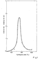
- Fig. 1 is a graph showing changes in coercive force after heat aging of a sintered alloy having the composition of at various temperatures.
- Fig. 2 is a graph showing the changes in coercive force with respect to aging time when a sintered alloy having a composition of is heat-aged at 750°C.
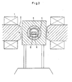
- Fig. 3 is a cross-sectional diagram showing an example of an apparatus for aging process in a magnetic field.
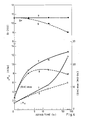
- Fig 4 is a graph showing the magnetic characteristic of a sample following aging process in a magnetic field at 750°C for up to 75 hours in comparison with that of a sample following aging process in a non-magnetic field under the same conditions.
- Component elements were weighed to make the composition of melted with arc in Ar atmosphere, and water-quenched to obtain an ingot in a copper mold. Then, the ingot was first roughly pulverized, then made into fine particles of 3 pm in average grain size with a vibration mill. This powder was oriented in a 10 KOe magnetic field and compression-molded under the pressure of approx. 5tt CM 2 to obtain green material. After the green material was vacuum-exhausted (about 10- 3 Torr), it was sintered by heating for 2 hours at 1180°C, furnace-cooled to room temperature, and used as a sample for aging tests.
- Green material was obtained in the same manner as in practical Example 1 from an ingot with the composition of Next, after sintering for one hour at 1200°C in vacuum, the material was furnace-cooled to room temperature and, in order to examine the state of aging, it was reheated to 750°C for preparing samples with varied heating time. The relationship between the heating time and coercive force was studied by measuring the coercive force of these samples, and the result shown in Fig. 2 was obtained. It is clear from the graph that the coercive force increases from 0.5 hr. showing state of saturation after 20 hrs and becoming constant.
- Ingots having the composition of where z 8.3, 8.5, 8.7, and 8.9, were prepared in the same manner as in practical example 1.
- the ingots were finely pulverized to average granular diameter of 2 ⁇ m with a vibration mill, oriented in a magnetic field and compression-molded to form green materials.
- Green material was obtained from an ingot having the composition of in the same manner as in practical example 1.
- Green material was obtained from an ingot having the composition of in the same manner as in comparative Example 1.
- the green material was vacuum-exhausted (about 10- 3 Torr) and sintered by heating for one hour at 1190°C, furnace-cooled to room temperature, and used as a sample for aging tests in a magnetic field.
- Part of this sample was magnetized: the sample was positioned in an electric furnace which was placed between the poles of electromagnets (Fig. 3) such that the direction of the orientation match the direction of the magnetic field generated between the magnetic poles (2), and aging process was carried out while energizing the electromagnets.
- the remaining sample was not magnetized and aging process was practiced in a non-magnetic field, and the two samples were compared.
- Fig. 3 the poles of electromagnets
Landscapes
- Chemical & Material Sciences (AREA)
- Crystallography & Structural Chemistry (AREA)
- Engineering & Computer Science (AREA)
- Physics & Mathematics (AREA)
- Thermal Sciences (AREA)
- Materials Engineering (AREA)
- Mechanical Engineering (AREA)
- Metallurgy (AREA)
- Organic Chemistry (AREA)
- Inorganic Chemistry (AREA)
- Power Engineering (AREA)
- Hard Magnetic Materials (AREA)
Abstract
Description
- This invention relates to a method of manufacturing rare earth-cobalt permanent magnet alloys.
- Rare earth metals and cobalt form various intermetallic compounds. Among them, the intermetallic compounds, RCo5, whose atomic ratio between rare earth metals (R) and cobalt (Co) is 1:5, exhibit extremely large magneto-crystalline anisotropy and have come to be used as permanent magnet alloy materials. In particular, an energy product of about 24 MG . Oe, a several times over the conventional alnico or ferrite permanent magnets, is obtainable with a SmCo5 permanent magnet in which R is samarium (Sm). SmCo5 is already being commercially produced.
- However, the desirable characteristics of a permanent magnet required in recent apparatus such as small rotary machines, small meters, detectors, etc., which utilizes air gap flux caused by a permanent magnet in a magnetic circuit, are a high residual magnetic flux density and a high energy product. Under such circumstances, the Sm2Co" intermetallic compound attracted attention since it has a higher saturation magnetization, a higher energy product and higher Curie temperature than SmCo5. In other words, the saturation magnetization of Sm2Co" reaches 12 KG, whereby, in theory, an energy product of 36 MG . Oe is obtainable. However, coercive force is not obtainable with the Sm2Co" permanent magnet, and it was necessary to drastically improve the coercive force of the intermetallic compound, Sm2Co17, in order to produce a permanent magnet.
- A method to improve the coercive force by partial substitution of Co with Cu or Cu and Fe, etc. has been reported as a measure to improve the coercive force as disclosed in US―A― 3,560,200. Furthermore, it became possible to increase the residual flux density and coercive force and to improve the angularity of demagnetizing characteristic, enabling the achievement of permanent magnet alloys that reach 30 Mg. Oe in energy product, (BH)max. However, the composition having such a characteristic was not the stoichiometric composition whose R-Co ratio is 2:17, but it was obtained with an alloy having the intermediate composition between the RCo5 phase and the R2Co17 phase. As mentioned above, sufficient magnetic characteristic could not be obtained with R2Co17 whose permanent magnetization has been desirable because of the high magnetocrystalline anisotropy saturation magnetization, and Curie temperature. Thus, it has not come to be commercially produced as a permanent magnet material. Furthermore, in order to develop it into a high performance magnet, the composition must truly be of the R2Co17 phase or constitutes mainly of a Co+R2Co17 compound having a greater Co component than in the R2Co17 phase, and it is necessary to partially substitute Co with Fe in order to obtain higher saturation magnetization.
- US-A-4,135,953 reports on permanent magnets produced by adding Cr, Mn, Ti, W, or Mo to R2 (Co, Fe)17 composition, and alloys of the composition that gained coercive force by sintering the above molded products at 1110-1180°C, followed by solid solution treatment and heat treatment at 400-600°C, as well as their manufacturing processes. However, the above invention is a manufacturing process for a liquid phase sintered magnet in which a powder sintering additive with low melting point is mixed in.
- DE-A-27 27 243 discloses a process for manufacturing permanent magnet alloys wherein an alloy of the formula

- It is an object of this invention to present an improved process for the manufacture of permanent magnet alloys having a high coercive force.
- This invention provides a process for manufacturing permanent magnet alloys wherein an alloy is finely powdered and compression-molded in a magnetic field or without impressing a magnetic field; and wherein said molded mass, following sintering at an elevated temperature in vacuum or in an inert atmosphere, is subjected to solid solution heat treatment and heat aging, characterized in that

- Preferably, the process according to the invention is further characterized in that a magnetic field of more than 0.5 KOe is impressed during aging. Preferably, the direction of impressing a magnetic field matches in parallel with the direction of orientation of the magnet during aging in the case of an anisotropic magnet.
- This invention involves weighing of various elements for the alloy composition,

- This invention presents the following heat aging process: the same objective can be achieved by reheating the material in the temperature range of 700-800°C, or in the process of cooling to room temperature following sintering, by cooling slowly during the temperature range of 700-800°C, or maintaining the temperature constant at 700-800°C before cooling to room temperature. The most effective heating time to provide heat aging at 700-800°C is 0.5-200 hours. In the case of heat aging at a temperature below 700°C, a sufficient increase in coercive force cannot be obtained, and the aging time is not effective either unless the heat treatment is more than 200 hours. Or, in the case of heat aging at a temperature above 800°C, it is above the eutectic temperature of the R2Co17 phase and the increase in coercive force, which is the objective of this invention, cannot be attained. Thus the most effective aging temperature is in the range of 700-8000C.
- However, this heat aging process revealed that while it provides the increasing effect of coercive force, it also includes an effect to reduce the magnetic characteristic by reducing the saturation magnetization of the material in the case of protracted aging. This is believed to be due to the fact that in the case of R2CO17 compounds, the temperatures in the vicinity of 750°C correspond to the eutectic temperature for these compounds, and reformation of crystals is accelerated during the protracted aging, at which time crystals develop in directions that mutually cancel the magnetic moments held by mutual crystals. Thus, in order to prevent a decrease in the magnetization during aging, the aging treatment was carried out while magnetically fixing the direction of the magnetic moments of the crystals. Then, it was confirmed that the initial saturation magnetization was maintained even after the protracted aging treatment, and in addition, the process contributed to an improvement in the angularity of the demagnetization curve.
- As for the method of magnetic fixation, the object of this invention can be achieved usually by carrying out the aging process while impressing a magnetic field from the outside of the heating furnace with an electromagnet, etc., or by carrying out the aging process while having the heated part in contact with or positioned nearby a magnet (e.g. alnico magnet) that can hold magnetism even in the temperature range of 700-800°C. The objective of this invention can also be achieved by applying the fact that the Curie temperature of R2C017 compounds is above 800°C and carrying out the aging process in the magnetized state by magnetizing the sintered mass once prior to the aging process. In this case, there is an effect to interfere with the decrease in magnetization by preventing the antiparallel coupling of the magnetocrystalline moment produced during the aging process by the intrinsic magnetic field held by the magnet. Also, it is necessary in the case of anisotropic magnets that the direction of the external magnetic field match the direction of orientation of the magnet. The strength of the magnetic field required for achieving the objective of this invention should be at least 1 KOe. The coercivity at 700-800°C, in the case of R2CO17 compounds, is known to decrease down to 10-30% of the coercivity at room temperature. Thus, the above value can be determined based on the fact that the alloys having the composition that includes this invention possess a coercive force of 5-10 KOe at room temperature state. However, the objective of this invention is achieved even at a strength of the magnetic field below 1 KOe, but it is insufficient to completely prevent a decrease in saturation magnetization.
- As a result, the addition of the aging heat process of this invention has effects of not only improving the coercive force, but enabling an improvement of the angularity of the demagnetization curve with respect to alloys related to this invention, whose chief constituent is a RzCoi7 intermetallic compound with which coercive force has been unobtainable in spite of the high saturation magnetization present. In regard to raw material cost, a magnetic alloy having a lower content of expensive rare earth components can be used, and a decrease in the expensive cobalt (Co) component is promoted by increasing the iron (Fe) component, thus having the effect of supplying an alloy with inexpensive materials compared with conventional alloys.
- Fig. 1 is a graph showing changes in coercive force after heat aging of a sintered alloy having the composition of

- Fig. 2 is a graph showing the changes in coercive force with respect to aging time when a sintered alloy having a composition of

- Fig. 3 is a cross-sectional diagram showing an example of an apparatus for aging process in a magnetic field.
- Fig 4 is a graph showing the magnetic characteristic of a sample following aging process in a magnetic field at 750°C for up to 75 hours in comparison with that of a sample following aging process in a non-magnetic field under the same conditions.
- 1, coil; 2, magnetic pole; 3, adiabatic material and heater; 4, core pipe; 5, product container; 6, magnetic material; 7, aging in magnetic field; 8, aging in non-magnetic field.
- Next, the optimum form to carry out this invention is described by the following comparative examples and the specific practical example according to the invention.
- Component elements were weighed to make the composition of

- Green material was obtained in the same manner as in practical Example 1 from an ingot with the composition of

- Ingots having the composition of


- Green material was obtained from an ingot having the composition of

- This was sintered in vacuum for one hour at 1200°C, furnace-cooled to 750°C, soaked for 2 hours at 750°C, and furnace-cooled to room temperature. Magnetic characteristic of this sample was measured and following results were obtained.
- Br=10.1KG
- iHc=4.45 KOe
- (BH)max=18.0 MG . Oe
- Green material was obtained from an ingot having the composition of

Claims (6)

Applications Claiming Priority (4)
| Application Number | Priority Date | Filing Date | Title |
|---|---|---|---|
| JP4833379A JPS55140203A (en) | 1979-04-18 | 1979-04-18 | Manufacture of permanent-magnet alloy |
| JP48333/79 | 1979-04-18 | ||
| JP102363/79 | 1979-08-11 | ||
| JP10236379A JPS5625941A (en) | 1979-08-11 | 1979-08-11 | Manufacture of permanent magnet alloy |
Publications (3)
| Publication Number | Publication Date |
|---|---|
| EP0029071A1 EP0029071A1 (en) | 1981-05-27 |
| EP0029071A4 EP0029071A4 (en) | 1983-02-09 |
| EP0029071B1 true EP0029071B1 (en) | 1986-01-29 |
Family
ID=26388583
Family Applications (1)
| Application Number | Title | Priority Date | Filing Date |
|---|---|---|---|
| EP80900442A Expired EP0029071B1 (en) | 1979-04-18 | 1980-11-04 | Process for producing permanent magnet alloy |
Country Status (4)
| Country | Link |
|---|---|
| US (1) | US4369075A (en) |
| EP (1) | EP0029071B1 (en) |
| DE (1) | DE3071376D1 (en) |
| WO (1) | WO1980002297A1 (en) |
Families Citing this family (13)
| Publication number | Priority date | Publication date | Assignee | Title |
|---|---|---|---|---|
| US4565587A (en) * | 1983-02-23 | 1986-01-21 | Crucible Materials Corporation | Permanent magnet alloy |
| CA1253720A (en) * | 1983-11-17 | 1989-05-09 | David J. Larson, Jr. | Ordered arrays of ferromagnetic composites |
| US4585473A (en) * | 1984-04-09 | 1986-04-29 | Crucible Materials Corporation | Method for making rare-earth element containing permanent magnets |
| US4723994A (en) * | 1986-10-17 | 1988-02-09 | Ovonic Synthetic Materials Company, Inc. | Method of preparing a magnetic material |
| WO1988004464A1 (en) * | 1986-12-10 | 1988-06-16 | Ios Spa | Rare earth-cobalt based magnetic material and permanent magnet |
| US4939121A (en) * | 1988-10-20 | 1990-07-03 | General Dynamics Corporation, Electronics Division | Method and apparatus for inducing grain orientation by magnetic and electric field ordering during bulk superconductor synthesis |
| US4911882A (en) * | 1989-02-08 | 1990-03-27 | Sps Technologies, Inc. | Process for producing permanent magnets |
| US5084115A (en) * | 1989-09-14 | 1992-01-28 | Ford Motor Company | Cobalt-based magnet free of rare earths |
| US5032355A (en) * | 1990-10-01 | 1991-07-16 | Sumitomo Metal Mining Company Limited | Method of manufacturing sintering product of Fe-Co alloy soft magnetic material |
| US5382303A (en) * | 1992-04-13 | 1995-01-17 | Sps Technologies, Inc. | Permanent magnets and methods for their fabrication |
| WO2002061769A1 (en) * | 2001-01-30 | 2002-08-08 | Sumitomo Special Metals Co., Ltd. | Method for preparation of permanent magnet |
| ES2543652B1 (en) * | 2013-12-30 | 2016-03-01 | Universidad De Sevilla | Method for powder metallurgy manufacturing |
| CN109155174A (en) * | 2016-03-30 | 2019-01-04 | 先锋磁体实验室有限公司 | Method of making permanent magnets |
Family Cites Families (16)
| Publication number | Priority date | Publication date | Assignee | Title |
|---|---|---|---|---|
| US3560200A (en) * | 1968-04-01 | 1971-02-02 | Bell Telephone Labor Inc | Permanent magnetic materials |
| FR2217430B1 (en) * | 1973-02-09 | 1976-10-08 | Matsushita Electric Industrial Co Ltd | |
| DE2507157C2 (en) * | 1974-02-21 | 1984-10-31 | Shin-Etsu Chemical Co., Ltd., Tokio/Tokyo | Permanent magnet and process for its manufacture |
| CH601484A5 (en) * | 1974-12-18 | 1978-07-14 | Bbc Brown Boveri & Cie | |
| US4116726A (en) * | 1974-12-18 | 1978-09-26 | Bbc Brown, Boveri & Company Limited | As-cast permanent magnet Sm-Co-Cu material with iron, produced by annealing and rapid quenching |
| JPS5211121A (en) * | 1975-07-18 | 1977-01-27 | Fujitsu Ltd | Magnet material |
| US4135953A (en) * | 1975-09-23 | 1979-01-23 | Bbc Brown, Boveri & Company, Limited | Permanent magnet and method of making it |
| CH603802A5 (en) * | 1975-12-02 | 1978-08-31 | Bbc Brown Boveri & Cie | |
| US4210471A (en) * | 1976-02-10 | 1980-07-01 | Tdk Electronics, Co., Ltd. | Permanent magnet material and process for producing the same |
| JPS52155124A (en) * | 1976-06-18 | 1977-12-23 | Hitachi Metals Ltd | Permanent magnetic alloy |
| US4213803A (en) * | 1976-08-31 | 1980-07-22 | Tdk Electronics Company Limited | R2 Co17 Rare type-earth-cobalt, permanent magnet material and process for producing the same |
| JPS53131222A (en) * | 1977-03-25 | 1978-11-15 | Tdk Corp | Permanent magnet material |
| JPS5386624A (en) * | 1977-09-14 | 1978-07-31 | Hitachi Metals Ltd | Permanent magnet alloy |
| JPS5386623A (en) * | 1977-09-14 | 1978-07-31 | Hitachi Metals Ltd | Permanent magnet alloy |
| JPS54104408A (en) * | 1978-02-03 | 1979-08-16 | Namiki Precision Jewel Co Ltd | Rare earthhcobalt base permanent magnet alloy |
| US4213802A (en) * | 1979-04-27 | 1980-07-22 | The United States Of America As Represented By The Secretary Of The Army | Method of treating a permanent magnet alloy |
-
1980
- 1980-02-29 WO PCT/JP1980/000038 patent/WO1980002297A1/en not_active Ceased
- 1980-02-29 DE DE8080900442T patent/DE3071376D1/en not_active Expired
- 1980-02-29 US US06/220,023 patent/US4369075A/en not_active Expired - Fee Related
- 1980-11-04 EP EP80900442A patent/EP0029071B1/en not_active Expired
Also Published As
| Publication number | Publication date |
|---|---|
| EP0029071A1 (en) | 1981-05-27 |
| WO1980002297A1 (en) | 1980-10-30 |
| US4369075A (en) | 1983-01-18 |
| DE3071376D1 (en) | 1986-03-13 |
| EP0029071A4 (en) | 1983-02-09 |
Similar Documents
| Publication | Publication Date | Title |
|---|---|---|
| US4773950A (en) | Permanent magnet | |
| EP0126802B1 (en) | Process for producing of a permanent magnet | |
| EP0134304B2 (en) | Permanent magnets | |
| US4762574A (en) | Rare earth-iron-boron premanent magnets | |
| US4747874A (en) | Rare earth-iron-boron permanent magnets with enhanced coercivity | |
| US4369075A (en) | Method of manufacturing permanent magnet alloys | |
| USRE31317E (en) | Rare earth-cobalt system permanent magnetic alloys and method of preparing same | |
| JP2774372B2 (en) | Permanent magnet powder | |
| EP0386286B1 (en) | Rare earth iron-based permanent magnet | |
| JPH04268051A (en) | R-fe-co-b-c permanent magnet alloy reduced in irreversible demagnetization and excellent in heat stability | |
| US4954186A (en) | Rear earth-iron-boron permanent magnets containing aluminum | |
| US5055129A (en) | Rare earth-iron-boron sintered magnets | |
| US4952252A (en) | Rare earth-iron-boron-permanent magnets | |
| US4981513A (en) | Mixed particulate composition for preparing rare earth-iron-boron sintered magnets | |
| US4878958A (en) | Method for preparing rare earth-iron-boron permanent magnets | |
| JPH0536495B2 (en) | ||
| JP3080275B2 (en) | R-Fe-Co-Al-Nb-Ga-B sintered magnet excellent in corrosion resistance and heat resistance and method for producing the same | |
| US4933009A (en) | Composition for preparing rare earth-iron-boron-permanent magnets | |
| US5015304A (en) | Rare earth-iron-boron sintered magnets | |
| JPH0536494B2 (en) | ||
| US5015306A (en) | Method for preparing rare earth-iron-boron sintered magnets | |
| JPH04143221A (en) | Permanent magnet manufacturing method | |
| JPH0794311A (en) | Nd-fe-co-b type sintered magnet | |
| JPH0620815A (en) | Manufacture of rare earth bonded magnet | |
| JPH04318152A (en) | Rare earth magnetic material and its manufacture |
Legal Events
| Date | Code | Title | Description |
|---|---|---|---|
| PUAI | Public reference made under article 153(3) epc to a published international application that has entered the european phase |
Free format text: ORIGINAL CODE: 0009012 |
|
| 17P | Request for examination filed |
Effective date: 19801107 |
|
| AK | Designated contracting states |
Designated state(s): CH DE NL |
|
| GRAA | (expected) grant |
Free format text: ORIGINAL CODE: 0009210 |
|
| AK | Designated contracting states |
Designated state(s): CH DE NL |
|
| REF | Corresponds to: |
Ref document number: 3071376 Country of ref document: DE Date of ref document: 19860313 |
|
| PLBE | No opposition filed within time limit |
Free format text: ORIGINAL CODE: 0009261 |
|
| STAA | Information on the status of an ep patent application or granted ep patent |
Free format text: STATUS: NO OPPOSITION FILED WITHIN TIME LIMIT |
|
| 26N | No opposition filed | ||
| PGFP | Annual fee paid to national office [announced via postgrant information from national office to epo] |
Ref country code: NL Payment date: 19870228 Year of fee payment: 8 |
|
| PG25 | Lapsed in a contracting state [announced via postgrant information from national office to epo] |
Ref country code: CH Effective date: 19880229 |
|
| PG25 | Lapsed in a contracting state [announced via postgrant information from national office to epo] |
Ref country code: NL Effective date: 19880901 |
|
| NLV4 | Nl: lapsed or anulled due to non-payment of the annual fee | ||
| REG | Reference to a national code |
Ref country code: CH Ref legal event code: PL |
|
| PG25 | Lapsed in a contracting state [announced via postgrant information from national office to epo] |
Ref country code: DE Effective date: 19881101 |