EP0029055B1 - Cycle a pedales oscillantes - Google Patents
Cycle a pedales oscillantes Download PDFInfo
- Publication number
- EP0029055B1 EP0029055B1 EP80901051A EP80901051A EP0029055B1 EP 0029055 B1 EP0029055 B1 EP 0029055B1 EP 80901051 A EP80901051 A EP 80901051A EP 80901051 A EP80901051 A EP 80901051A EP 0029055 B1 EP0029055 B1 EP 0029055B1
- Authority
- EP
- European Patent Office
- Prior art keywords
- pedal
- cycle
- levers
- chain
- pedal levers
- Prior art date
- Legal status (The legal status is an assumption and is not a legal conclusion. Google has not performed a legal analysis and makes no representation as to the accuracy of the status listed.)
- Expired
Links
Images


Classifications
-
- B—PERFORMING OPERATIONS; TRANSPORTING
- B62—LAND VEHICLES FOR TRAVELLING OTHERWISE THAN ON RAILS
- B62M—RIDER PROPULSION OF WHEELED VEHICLES OR SLEDGES; POWERED PROPULSION OF SLEDGES OR SINGLE-TRACK CYCLES; TRANSMISSIONS SPECIALLY ADAPTED FOR SUCH VEHICLES
- B62M1/00—Rider propulsion of wheeled vehicles
- B62M1/24—Rider propulsion of wheeled vehicles with reciprocating levers, e.g. foot levers
- B62M1/28—Rider propulsion of wheeled vehicles with reciprocating levers, e.g. foot levers characterised by the use of flexible drive members, e.g. chains
-
- Y—GENERAL TAGGING OF NEW TECHNOLOGICAL DEVELOPMENTS; GENERAL TAGGING OF CROSS-SECTIONAL TECHNOLOGIES SPANNING OVER SEVERAL SECTIONS OF THE IPC; TECHNICAL SUBJECTS COVERED BY FORMER USPC CROSS-REFERENCE ART COLLECTIONS [XRACs] AND DIGESTS
- Y10—TECHNICAL SUBJECTS COVERED BY FORMER USPC
- Y10T—TECHNICAL SUBJECTS COVERED BY FORMER US CLASSIFICATION
- Y10T74/00—Machine element or mechanism
- Y10T74/21—Elements
- Y10T74/2164—Cranks and pedals
- Y10T74/2168—Pedals
- Y10T74/217—Pedals with toe or shoe clips
Definitions
- This invention relates to an oscillating pedal cycle.
- Conventional rotary pedal type bicycles have enjoyed wide usage over the years. They have the advantages of simplicity and ease of manufacture. However, they are also very restricted in their mode of operation and are limited in their capabilities. For example, considering a conventional ten-speed bicycle having a 68.5 cm wheel diameter, and a ratio of 3.6 revolutions of the rear wheel to 1 revolution of the pedals, and assuming that the ten speed bicycle is in high gear, and that the rider is making 60 strokes per minute with each leg, or one revolution per second of the pedals, under these conditions the bicycle will be travelling at a speed of approximately 27.7 km per hour or approximately 7.7 metres per second. No flexibility is provided in the application of power to the pedals.
- the rider must either fully rotate his legs at the rate of 60 times a minute or he cannot apply force to the rotating wheels. There is no possibility for the rider to shorten his stroke or apply brief impulses of high power to the bicycle. It is not possible to apply force with both legs to the two pedals simultaneously, if this should be desired.
- the conventional bicycle is therefore severely limited in its capabilities, as its mechanical limitations inflexibly dictate the mode of operation of the rider.
- the diameter of the circle through which each pedal rotates is about 33 cm.
- power is only applied to each pedal on the downward stroke during about 180 degrees.
- the toe normally engages the pedal.
- the cosine of the angle ranging from 100% at 0 degrees (horizontal) to zero at plus and minus 90 degrees when the pedal is at the top and bottom of its stroke.
- 50% of the downwardly applied force is effective; and at plus and minus 30 degrees, about 87% of the force is effectively translated into rotational torque, neglecting friction.
- an oscillating pedal cycle in correspondance with the precharacterising part of claim 1 has been disclosed in German Offen- legungsschrift No. 2,511,663.
- This cycle includes a frame, front and rear wheels and a seat; and pedal levers, for applying power to drive the cycle, having a predetermined range of reciprocating or oscillating movement.
- the pedal levers comprise a front member and a rear member rigidly connected together, and are mounted for operation wholly independently of each other.
- Pedals, secured to the front of the pedal levers are provided with restoring means including means for engaging the foot or shoe of the rider, to restore the front of the pedal levers to an upper position thereof.
- the cycle further includes a chain, one end of which is attached to the rear member at a driving point to drive the rear wheel of said cycle; and the other end of which is attached to a spring for maintaining the chain under tension.
- a cycle including: a frame, front and rear wheels, and a seat; means including a pair of pedal levers each having a predetermined range of reciprocating or oscillating movement for applying power to drive said cycle; pedal means secured to the front of said pedal levers for engagement by the feet for driving said cycle, each of said pedal levers having a front member and a rear member rigidly connected together, and an intermediate pivot point substantially where said two members join, said pedal levers being mounted for operation wholly independently of one-another, whereby said pedal means may be operated with different length strokes, or together, or alternatively, with equal length strokes, and with the pedal raising motion at a different and more rapid or slower speed than the power stroke; means for restoring the front of said pedal levers to their upper positions, including means associated with each pedal means for engaging the foot or shoe of the rider; chain or belt means having one end coupled to the rear member of each of said pedal levers at a driving point to drive the rear wheel of said cycle; and means connected to the other end of
- each of the pedal levers may be coupled by separate clutches to the rear hub of the bicycle.
- the means for engaging the foot or shoe of the rider may be, for example, heel clips or members which engage the rider's instep.
- Said pedal means may comprise forwardly mounted foot platforms which have a pivot point about 8 to 12 cm forward from the rear of the rider's heel.
- the distance from the pivot point of the pedal lever to the pivot point of the pedal platform, or the radius of the pedal motion, is preferably about 28 to 36 cm, which is approximately equal to the diameter between pedals of a conventional bicycle.
- the full stroke of the pedal lever may extend through an arc that is more than 60 degrees and less than 120 degrees (and preferably in the order of 85 degrees) so that the average efficiency is more than 90%.
- the motion of the rear member of the pedal lever assembly is confined to the space to the rear of the seat and away from the operating positions of the rider's legs and ankles to avoid possibility of injury to the rider, and for cleaner mechanical design.
- the pedal lever serves to interconnect the driving point where the chain is effectively connected, the pivot point for the pedal lever and the pedal mounting point for the pedal platforms.
- the pedal levers may assume various configurations, it is desirable that the angle including the pivot point of said pedal lever as an apex and extending from said driving point on the rear member to the mounting point for said pedal means on the front member, is an oblique angle, directed downward and to the rear when said pedal levers are in an intermediate position.
- the oblique angle is preferably more than 145 degrees, and successful results have been obtained using an oblique angle in the order of 150 to 170 degrees.
- each of the pedal levers carries a slider which may be locked in position and moved by remote controls operated by the rider with the pedal levers in any orientation.
- a locking element forming part of each of the sliders is first positively moved to unlock the slider, and then the sliders are moved longitudinally to change the speed ratio.
- the rear member of the pedal lever may include two side members, and an interconnecting transverse plate, providing a beam of H-shaped cross-section, with the transverse plate forming a camming surface to release the slider from locking recesses in the pedal lever portion.
- Other known beam cross-sections such as “T”, “U”, “I”, “L”, or cross configurations may be used to provide the desired mechanical strength, locking recesses for the slider in the form of notches or holes in the beams, and camming surfaces to unlock the slider.
- the front member of the pedal lever may be bent between the pivot point and the pedal to increase the length of the stroke and, in one embodiment, to avoid interference with the tensioning means.
- each of the pedal levers may be of T-shaped or L-shaped configuration, or other beam configurations of high mechanical strength and low weight.
- the tensioning means may comprise a spring with one end thereof secured to the lower end of the cycle chain and the other end thereof mounted at a point between the pivot point of the pedal lever and the point of attachment of the pedal lever when it is at the lowest point of the power stroke.
- the slider for changing the cycle gear ratio may be controlled by a cable which is both shifted in longitudinal position and also rotated, so that the slider movement and its locking may be independently controlled by a single cable.
- Each chain may be provided with quick release arrangements at either or both of its upper end where it engages the movable slider on the pedal lever, and its lower end where it is secured to such a spring.
- each chain may be displaced inwardly toward the frame of the cycle out of the plane of movement of the pedal levers to permit greater flexibility in design.
- Each such spring may be secured to the front member of the pedal lever to provide a degree of automatic tension adjustment as the chain is operated.
- embodiments of the present invention provide a cycle in which the rider controls the application of power to the cycle instead of having the cycle dictate the mode of application of power to it by the rider; a way of increasing the efficiency of the application of human power to propel a cycle and significantly reducing the complexity of variable speed or variable ratio cycles.
- the cycles according to embodiments of the present invention are mechanically sound, have a minimum number of parts, and minimum maintenance requirements.
- Another advantage involves the significant reduction in distance travelled by the foot in the present cycle, as contrasted with conventional cycles. Assuming a stroke from top to bottom of 33 cm, for both a conventional cycle and for the present oscillating pedal type one having a pedal radius (instead of diameter) equal to the same 33 cm, the distance travelled by each foot in a conventional cycle will be in the order of50% greater than with the cycle in accordance with the invention. Further, as noted above, the direct extension of the leg and the application of force onto the firm pedal platform results in much higher energy conversion efficiency than is obtained with rotary pedal action using toe engagement required for the smooth pedalling of conventional cycle. In the present cycle, the cycle powering stroke may vary from 2.5 cm up to 45.7 cm, and may even be increased to close to 50.8 cm, without interfering with the mounting of such a spring or otherwise interfering with good cycle design requirements.
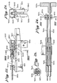
- Figure 1 shows an oscillating pedal type bicycle including a front wheel 12, a rear driving wheel 14, a frame 16 which happens to be in the form of a woman's type bicycle, and a seat 18.
- the bicycle is provided with two pedal levers 20 and 22, with the pedal lever 20 being on the near side of the bicycle frame, and pedal lever 22 being on the far side of the bicycle frame, as shown in Figure 1.
- Pivotally mounted at the front of the pedal levers are pedal platforms 24 and 26. These pedal platforms are arranged with a pivot point in the order of 10.16 to 12.70 cm forward the position of the heel of the rider in order to provide more direct power from the rider's legs on to the front ends of the pedal levers, instead of the usual application of pressure by the toe of the rider on to the pedals.
- the pedal lever 20 and associated mechanism are better shown in Figure 2 of the drawings. More particularly, the pedal lever 20 includes a front pedal supporting member 28 having a mounting point 134 for mounting a pedal platform and a rear power transmission member 30. These two members are fixedly secured together, and make an oblique angle with one another. The apex of this oblique angle points downwardly and to the rear. The oblique angle as shown is approximately equal to 150°, but it is contemplated that it could extend from about 120° to about 170°.
- the centrally located pivot point 32 is located substantially intermediate the two members, and secures the pedal lever 20 to the frame of the bicycle. Each pedal lever is provided with a lower stop which stops the pedal platform about 8 to 13 cm above the ground and provides a full range of arcuate movement for the pedal lever of somewhat less than 90°.
- the rear wheel 14 of the bicycle is driven through clutches which are included in a hub 34.
- the hub 34 may be provided with two sprocket gears, one for each of chains 36 and 38 associated with the pedal levers 20 and 22, respectively.
- the chain 36 is secured to the end of the member 30 at a point 40. It extends over a roller 42 on a slider 44 which is selectively locked in position at different points along the length of the transmission member 30 to determine the speed or ratio of the bicycle.
- the other end 46 of the chain 36 is secured to a constant tension flat roll-type spring 48 which is mounted on a drum 50, pivotally mounted on the frame.
- Figure 3 shows a slightly modified version of the arrangement shown in Figure 2, in which the constant tension spring 48 is mounted on a drum 32a, and to the bicycle frame at the point where the pedal lever 20 is pivoted.
- the details of the locking and release mechanism for the slider 44 over which the chain 36 passes are disclosed in Figures 4 and 5. More specifically, the chain 36 normally exerts a force directed to the left as shown in Figure 4.
- the transmission member 30 is actually made up of two side plates 52 and 54 bridged by a transversely extending plate 56 upon which a roller 58, pivotally secured to the slider 44, rides.
- two cables having outer housings 60 and 62 are shown with their outer coaxial sleeves secured to the transmission member 30 by a bracket 64.
- a movable wire 66 which slides within the outer housing 60 is actuated to release the slider 44 from its normally locked position in which a locking axle 68 is located within one of recesses 70.
- the release function is accomplished by a camming member 72 which pivots in the slider 44 at a point 74.
- a camming member 72 which pivots in the slider 44 at a point 74.
- tension is applied to an upper point 76 of the camming member 72, the rear of slider 44 is raised as a roller 78 presses against transversely extending plate 56. This action raises locking axle 68 out of the recesses 70 in side plates 52 and 54 so that it is free for longitudinal movement.
- the slider 44 With regard to longitudinal movement of the slider 44, it is normally biased to the rear by the force of the chain 36. On the other hand, the application of tension to a wire 80 moves the slider 44 to the right, as shown in Figure 4, thereby reducing the amount of travel of the chain 36 for a given angular movement of the transmission member 30. On the other hand, when it is desired to go faster, and to increase the ratio of wheel rotation to angular movement of the transmission member 30, the slider 44 is shifted to the left, and the locking axle 68 is located in one of the outer sets of recesses 70 on the member 30. This movement to the left may be accomplished by operating the movable wire 66 and then relaxing tension on the wire 80 so that the slider 44 will move to the left under the force provided by the chain 36.
- an alternative slider 44' is riding on the transmission member 30'.
- the pedal lever member 30' is provided with recesses 70' which are slightly asymmetric, to counteract the normal biasing force exerted by the chain 36 toward the rear of the member 30'.
- the position of the slider 44' is controlled by a cable wire 82 which is movable within an outer concentric cable housing 84, which has its lower end secured to the member 30' by a bracket 86.
- the position of the slider 44' is controlled by a camming and control member 88, pivoted at a point 90 and having a cam 92 rigidly secured to it.
- a pin at point 90 normally drops down into one of the recesses 70'.
- the arrangement of Figure 6 may be provided with an additional cable 98 having a housing and an inner actuating wire 100 to provide separate movement control for the slider 44' along the transmission member 30'.
- the cable housing 84 may be mounted by a bracket 102 on the movable slider 44', rather than on the arm 30' as shown in Figure 6.
- the end of the outer concentric housing 98 enclosing the tension member or inner wire 100 is secured to member 30' by a bracket 104.
- Figure 8 shows a cable control drum assembly 106 mounted by a bracket 108 to the front frame or to the handle bars of the bicycle where it may be easily reached by the rider.
- the arrangement of Figure 8 is intended for association with the two cable arrangements shown in Figure 7. More specifically, note that the outer concentric housing 98 passes through the bracket 108, and is therefore rigidly held to the frame of the bicycle.
- the entire drum assembly 106 is rotated on the bracket 108, by grasping a handle 110.
- the release cable is' mounted by a bracket 102 on to the drum assembly 106 to rotate with it.
- a smaller handle 114 is moved in the clockwise direction to apply tension to movable wire 66 and raise the locking axle out of the locking recess in member 30'.
- the speed or ratio of the bicycle may be changed by moving the position of the slider through the rotation of the drum assembly 106 under the control of handle 110.
- either one or two of the assemblies 106 may be provided. More specifically, if it is always desired to actuate both pedals with precisely the same gear ratio, then a single assembly 106 may be provided, with the cables for both of the two sliders secured thereto. However, if a rider has one leg which is somewhat weaker than the other and wishes to have a different ratio, then it is quite practical to provide two drum assemblies so that one of the transmission members 30 may be adjusted to a high ratio while the other is at a somewhat lower ratio.
- Figure 9 shows another alternative method for unlocking and shifting the slider mechanism 44 on the rearwardly extending member 30 of the pedal lever which is pivoted at 32.
- a cable is provided in which an inner wire 116 and an outer concentric housing 118 move together in order to change the position of the slider 44, but the inner wire 116 is shifted relative to the housing 118 in order to unlock a detente 120 from the recess 70 in which it is seated when in the locked position.
- the slider 44 is provided with the roller 50 which rides on the transversely extending plate 56, and a release mechanism 122 is pivoted about a point 124 under the control of wire 116 to force roller 126 into engagement with the plate 56 so that detente 120 is raised out of any one of the recesses 70 in which it may be locked. Thereafter, the entire cable comprising housing 118 and wire 116 is moved to permit the slider 44 to move along the rearwardly extending member 30 of the pedal lever.
- This movement of slider 44 on member 30 may be either under the force of the chain 36, as described above, which would move the slider to the left as shown in Figure 9, or by rotation of a drum on which the housing 118 and wire 116 may be wrapped, to move it to the right as shown in Figure 9 against the spring pressure on the spring 36.
- the actuating mechanism for the cable comprising wire 116 and housing 118 of Figure 9 may be substantially as shown in Figure 8, with the entire cable including the housing 118 being secured in a manner similar to cable housing 60 as shown in Figure 8 to extend around and be actuated in its entirety by the rotation of the drum assembly 106, but with the smaller handle 114 supplementally moving the inner wire 116 relative to the housing 118 which is fixed to the drum (not the frame of the bicycle).
- the housing 118 must move longitudinally, and rollers such as externally grooved roller 128 shown in Figure 9 are provided on the frame of the bicycle between the drum assembly 106 and the pulley or roller 128.
- FIG 10 and 11 are schematic diagrams of one of the pedal platforms 24 pivotally mounted at the front end of forwardly extending pedal supporting member 28 of the pedal lever 20, as shown in Figures 1 and 2.
- the pedal platform 24 includes an underlying plate 132 which is pivotally mounted to the forward pivot point 134 (see Figure 2) by a bracket.
- Spring heel clips 138 are preferably provided for each of the pedal platforms 24, and these may be adjustably mounted to the underlying plate 132 by a bracket 140 pivotally secured to a vertically extending member 142, which is in turn adjustably mounted to extend within a hollow lower support member 144.
- the heel clips 138 may be adjusted to the proper size for the rider and then clamped in the proper position by clamping mechanisms 146 and 148 which may be of any suitable configuration. It has been determined that the preferred way of raising the pedals and restoring them to their upper positions between strokes is through the use of heel clips secured to the heels, and by providing the motive power by the rider. This permits freedom of control by the rider without arbitrary constraint being forced upon the rider by the mechanism of the bicycle. Other oscillating pedal type bicycles have provided restoring springs, or interconnecting mechanisms whereby the depressing of one pedal raises the other pedal; however, such arrangements have introduced unnecessary back or reverse pressure, or have unduly constrained the mode of operation of the bicycle. Accordingly, the inventor has determined that restoration under the control of the rider through the use of heel clips, such as those shown in Figures 10 and 11, are to be preferred.
- Figure 12 shows an alternative arrangement in which a special shoe 160 is provided with a metal attachment 150 for engaging a slot 152 mounted at the rear of a pivoted pedal platform 154.
- the pedal platform 154 is pivotally mounted on the pedal supporting member 28.
- An additional bracket 156 is provided for engagement with the front left-hand side of the shoe 160.
- the arrangement of Figure 12 is primarily intended for racing bicycles in which special shoes may be employed.
- FIG 13 is a diagrammatic representation of the mode of biasing or orienting the pedal platforms, such as pedal platform 24 mounted at the front end of the pedal support member 28 of pedal lever 20 (see Figures 1 and 2).
- a torsion spring 162 is employed to orient the pedal platform 24 relative to the pedal support member 28. More specifically, in the absence of the torsion spring 162, the high centre of gravity of the pedal platform 24 could turn it over so that a rider could not easily place his foot upon it. Accordingly, the orientation of the pedal platform 24 relative to the end of the pedal support member 28 of the pedal lever is determined by the torsion spring 162.
- One end of the torsion spring 162 extends through an opening 164 in an upwardly extending bracket 166 forming part of the pedal platform 24.
- the other end of the torsion spring 162 may be inserted into any one of a series of holes 107 in the end of the pedal support member, so that the proper angular orientation of the pedal platform 24 is obtained.
- the spring can be of greatly reduced extent, and may be on the inner side of the front end of the pedal support members, with a pivot rod 172 extending through to the left-hand side of pedal support member 28, as shown in Figure 13, and being rigidly secured to the pedal platform 24. The torsion spring could then be secured to the pivot rod 172 and hold it in the desired orientation relative to the pedal lever.
- Figure 14 shows yet another arrangement for unlocking the slider 44 from the rear power transmission member 30 and shifting its longitudinal position. More specifically in the arrangement of Figure 14, unlocking is accomplished by a release cable 176 which rotates a circular cam 178 about a combined pivot point and locking rod 180.
- Figure 14 shows the locking rod 180 raised up out of the locking recesses 70, with the cam 178 riding on the transversely extending plate 56.
- the position of the slider 44 may be moved by actuation of a speed ratio control cable 182 which is secured to the member 30.
- the slider By rotating the drum assembly 106, as shown in Figure 8, with the handle 114 depressed, the slider may be moved to the left or right to change the speed ratio of the bicycle.
- Figure 14 is of interest in showing an arrangement in which the speed ratio control cable 182 operates below the member 30, while the release cable 176 operates above the member 30.
- Figure 15 shows an arrangement in which a slider 184 is moved along the member 30 by a single movable cable 186.
- a detente 188 is initially raised up out of the recess 70 in which it is located, and then the slider 184 moves to the right as shown in Figure 15, to shift the detente 188 to the next subsequent locking recess 70.
- the cable 186 may be momentarily pulsed, and then released so that the detente 188 would move upward and to the left as shown in Figure 15 under the pressure of the chain 36.
- FIG 16 shows an alternative arrangement in which a flexible drive belt or cable 192 is employed instead of the chain 36 shown in other embodiments.
- the belt 192 is secured to and wraps around a hub 194 at the rear wheel of the bicycle.
- the hub 194 is coupled to the rear wheel by means of a roll type locking clutch with very little back play, as will be described below.
- the hub 194 is biased at an angular orientation by a return spring 196 which is indicated schematically in this Figure.
- a flat constant force spring 198 is secured to the outer end of member 30 by a bolt 200, and is pivotally mounted on the slider 44 to bias it toward the end of member 30.
- a cable or belt 202 is actuated to both unlock and move the slider 44 along the length of the member 30, as in earlier embodiments.
- FIG 17 shows another embodiment employing a drive belt, instead of a chain.
- the belt 192 is secured to the movable slider 44, which is mounted as shown near the outer end of the transmission member 30.
- the constant force spring 198 is secured to the outer end of the member 30, and is rotatably mounted on the slider 44 at a pivot point 206 to urge the slider 44 toward the outer end of member 30.
- Locking and unlocking of the slider 44 is accomplished by a cable 208 in a manner discussed hereinabove in connection with other embodiments, and movement of the slider 44 along the length of member 30 is accomplished by a cable 210.
- Figure 18 shows an alternative arrangement in which a single cable 214 performs both the unlocking and the control function for moving a slider 216 in a rearwardly extending portion 218 of a pedal lever.
- balls 220 extend outwardly into locking recesses 222 in the rearwardly extending portion 218.
- the initial action is to compress a spring 224, with an element 226 moving to the right to engage the main portion of slider 216 which lies to the right of the element 226.
- the balls 220 move inwardly to release the slider 216 so that it may move either to the right under continued tension exerted on cable 214, or to the left under the force of a chain or belt 228 secured to the slider 216.
- FIG 19 shows the rear wheel hub assembly. More specifically, a wheel hub 232 supports spokes 234 which extend outwardly and are connected to the rim of the wheel which carries the tyre.
- Two outer sprockets 236 and 238 receive the chains which are connected to the rearwardly extending portions of the pedal levers 20 and 22 as shown in Figure 1.
- roller clutches 240 and 242 Immediately within the sprockets 236 and 238 are roller clutches 240 and 242, respectively, which transmit torque on a unidirectional basis to the wheel hub 232.
- Roller clutches perform a function similar to a ratchet in that torque is transmitted in one direction, but not in the other.
- roller clutches of modern design have virtually no lost motion and are virtually instantaneously put into operation upon reversal of motion.
- a plastic washer 244 mounted outside the clutch 242 is a plastic washer 244, which is held in place by a retaining ring 246.
- a similar washer and retaining ring are located at the other end of the assembly.
- the frame of the bicycle is mounted on threaded surfaces 248 and 250, and is held in place by the usual retaining nuts.
- the other components shown in Figure 19 are generally conventional.
- the driving chain 36 may be relatively short. More specifically, it is preferably in the order of 40.64 to 50.80 cm long for a 68.58 cm wheel, with a shorter range of lengths being appropriate for smaller bicycles, or bicycles with a reduced range of speed ratios. This short length precludes the transverse vibrations which tend to plague the operation of bicycles having extending tension members.
- the inertia of the reciprocating chain assembly is held to a minimum in that the only other working part that moves back and forth with it is the sprocket gear on hub 34, the flat constant tension spring 48, and the lightweight coupling between spring 48 and the short bicycle type chain 36.
- the spring 48 has a tension of only about 1.6 kilograms, and is preferably between 1.1 and 2.3 kilograms.
- Another minor feature involves the provision of the vertical toe plates or brackets such as 156 on the inner side of the pedal platforms, to prevent inadvertent inward sliding of the front of the shoe into engagement with the frame of the bicycle.
- this bicycle is similar in many respects to those described hereinabove in connection with Figures 1 to 19.
- the bicycle includes a front wheel 302, a rear wheel 304, a seat 306, and handlebars 308.
- the part of the bicycle which is of greater interest to us in connection with Figure 20 is that relating to the drive mechanism, and specifically including two pedal levers, with the one in the foreground including a front portion 310 and a rear portion 312, and the one in the background including a front portion 314 and a rear portion 316 which is nearly in the vertical orientation.
- Suitable pedal platforms as described hereinabove are mounted on the pedal levers at 318 and 320.
- a slider 322 which may be moved along the rear portion 312 of the pedal lever to change the effective gear ratio of the bicycle, a chain 324 which drives the bicycle, and a constant force spring 326 which is secured to the other end of chain 324 and is mounted at a point 328.
- the chain and spring associated with the rear pedal lever, as shown in Figure 20, are not visible, but the constant force springs are mounted coaxially at a point 328 on each side of the frame and rear wheel 304.
- a gear changing and locking control mechanism 332 is provided with a handle 334, and the entire unit is mounted conveniently on the bicycle frame.
- Figure 21 is an enlarged showing of one of the pedal levers including the front portion 310 and the rear portion 312, which has a central pivot journal 336. It may be noted that the front portion 310 of the pedal lever is bent up in the region 338. As shown in Figure 20, this permits a longer stroke for the forward portion of the pedal lever without interfering with the mounting point 328 for the constant force spring retractors for the chain.
- a stop structure 337 provides resilient material in the path of both of the two pedal lever portions 310 and 314, to stop their downward travel, and to preclude their impingement on the ground.
- Figures 22 and 23 illustrate one gear changing arrangement for the bicycle of Figure 20. More specifically, the upper surface of the rear portion 312 of one of the pedal levers is provided with a series of notches or recesses 340 into which the slider 322 is secured by a detent 343, and held by a cam 342. With the detent 343 and cam 342 oriented as shown in Figures 22 and 23, detent 343 engages one of the recesses 340, and prevents the slider 322 from moving up or down the portion 312.
- a cable 344 When it is desired to change gears, a cable 344 is rotated, and the cam 342 is moved out of engagement with a stop 346, thereby unlocking the detent 343 and permitting free longitudinal movement of the slider 322 as a result of the angle between detent 343 and the end wall of recess 340, as a result of the longitudinal force on slider 322.
- Such longitudinal movement is accomplished by the action of the cable 344 as it is moved from left to right or vice versa as shown in Figure 22.
- the cable 344 is clamped by a clamping mechanism 348 on to the slider 322, and more specifically in engagement with the rotating cam 342.
- This rotating cam 342 is in turn journalled within an opening 350 in a housing of the slider 322, and is retained in position by a heavy sheet metal bracket 352 which extends around the rear of the cam 342.
- the upper end of the chain 324 (see Figure 20) is secured in a recess 356, so that it may be readily detached when the bicycle is to be disassembled or repaired.
- bolts 358 hold the bracket 352 in place.
- Figures 24 and 25 show the controls for the gear changing arrangements which appear in Figure 20 at reference numerals 332 and 334, with 334 indicating the handle.
- the handle 334 is pulled or pushed to control the longitudinal position of rods 362 and 364 and their associated cables 344 and 366, respectively.
- the mechanism 332 is secured to the frame by suitable brackets such as the bracket 368.
- a gear box 370 including a gear 372 secured to rod 362, and a gear 374 secured to rod 364 cause the shafts to rotate in opposite directions simultaneously, when the handle 334 is turned.
- rotation of the handle 334 in the opposite direction releases the detent 343 and permits the changing of the effective gear ratio by the longitudinal movement of the slider 322 when the. handle 334 is pulled or pushed.
- it prior to changing the gear ratio by longitudinal movement of the handle 334, it must first be rotated to release the detent 343, as discussed above.
- an outer housing 345 of cable 344 is fixed at one end to mechanism 332, and at the other end to the rear portion 312 of the pedal (see Figure 22).
- Figures 26 and 27 show top and side views, respectively, of the chain 324 and the quick release arrangements for securing the chain 324 to the slider 322 and the constant force spring 326. More specifically, at one end the chain is provided with a coupling member 382 which has a central width between pins 384 and 386 which is a close fit to slide between members 388 and 390 of slider 322 as shown in Figure 23. In addition, the pins 384 and 386 are sized to fit into the recesses 356 in both members 388 and 390.
- the constant force spring 326 is provided with a pair of clamping members 392 and 394 and a transversely extending pin 396 having an extension 398 which is directed toward the main portion of the spring 326.
- the chain 324 is provided with an end member 402 having an opening 404 for receiving and engaging the pin 396. Accordingly, with the arrangements as shown in Figures 26, 27 and 22, the chain 324 may be released both from the slider 322 and from the constant force spring 326 in a matter of seconds. On the other hand, once the members are assembled, the tension of the spring 326, and the close fit of the elements in operation, prevent their inadvertent release.
- Figure 28 shows the arrangements for mounting the constant tension spring 326 on a bicycle frame member 408, at the position of the mounting point 328 which appears in Figure 20 of the drawings.
- the spring 326 is mounted in a spool shaped holder 410 which is freely rotatable on a mounting pin 412 which is adjustably secured into an opening 414 in the bicycle frame 408 by a set screw 416.
- a spring 418 maintains the housing 410 in engagement with the enlarged head 420 of the pin 412.
- an open "H" type configuration may be employed as shown at 312' in Figures 29, 30 and 31.
- the central portion of the portion 312', as shown in Figure 29, includes two side frame members 424 and 426, which are secured together, both at their outer ends by an element 428, and toward the pivot journal 336 by webbing 430.
- the slider arrangement of Figures 29 through 31 is similar to that of Figure 28 as disclosed hereinabove.
- the cable 432 with its inner movable wire 434 serves to both move the slider longitudinally on the portion 312' and also to selectively release the latching mechanism.
- the arrangements for operating the cable 432 would not be as shown in connection with Figures 24 and 25 of the drawings, but would be as described hereinabove in connection with Figures 8 and 9.
- the housing of the cable 432 is secured to the main body of the slider 436.
- the inner wire 434 is secured to a cam actuator lever 438 which turns a shaft 440 about its axis when the central wire 434 is moved longitudinally relative to the housing of cable 432.
- a cam actuator lever 438 Secured to the shaft 440 to rotate with it are two cam members 442, which bear on inwardly extending rails 444 secured to the side members 424 and 426 of the pedal lever portion 312'.
- a roller 446 also rides on the inwardly extending rails 444.
- the chain 324 is secured to member 450 which is pivotally mounted for free rotation on the centre of the shaft 440.
- Spring elements 451 are mounted on a pin 454 to bias the slider 436 counterclockwise about the roller 446 to maintain the shaft 440 in engagement with the recesses 448 when the cams 442 are not operated.
- the bicycle includes the same basic front and rear wheels 302 and 304, seat or saddle 306, and handlebars 308 as in prior embodiments.
- the frame includes a main vertical support 470, and angular bracing members 472, 474, 476 and 478, which are arranged to provide additional strength and support at a pivot point 480 for the pedal levers, including the front portion 482 and the rear portion 484.
- a resilient stop 486 is firmly secured to the frame, and limits the downward movement of each of the pedal levers by engagement with the front portion 482.
- an independently movable pedal lever not visible in Figure 32, is mounted to pivot about the same pivot point 480.
- the two pedal levers may be operated either synchronously or alternately; therefore, the other pedal lever may be oriented precisely behind that shown in the foreground in Figure 32.
- a slider 488 which is movable along the length of the portion 484 to change the effective gear ratio of the bicycle.
- the chain 324 extends over a sprocket 490, and the free end of the chain is secured to a constant force spring 326 mounted at point 328 on the bicycle frame.
- Figure 33 is a top view of the rear portion 484 of the pedal lever, together with a more detailed showing of the configuration of the slider 488 which is mounted on portion 484.
- the slider 488 is provided with a detent 494 which may be locked into any of recesses 496 in portion 484 to hold the slider 488 in its proper position along the length of the portion 484, thereby determining the lever arm through which force is applied to the chain 324 to drive the bicycle.
- the detent 494 is selectively held in place in one of the recesses 496 by a cam 498 which is rotated with the rotation of the control cable 344, in the manner described hereinabove for cam 342, in connection with Figures 22 and 23 of the drawings.
- the detent 494 When the cam 498 is rotated to its inactive position, the detent 494 is pivoted to rotate about a point 502 (see Figure 33), and longitudinal pressure on the slider 488 will cause the detent 494 to pop out of the recesses 496 to permit changing of the effective gear ratio of the bicycle.
- the cable 344 When the slider 488 has been shifted to a new position, the cable 344 will be rotated so that the detent 494 is held into its new position in another recess 496 by the cam 498.
- the chain 324 may be secured to the slider 488 as shown in Figure 34 so that plane of the chain is not aligned with the plane of movement of the portions 484 and 482 of the pedal lever.
- the spring 326 need not be aligned with the front portion 482 of the pedal lever, and may be mounted at the point 328 inside the path of travel of the front portion 428 of the pedal lever so that the pedal lever may swing past the constant force spring mounting point 328.
- Figures 24 and 25 One arrangement for moving the two cables longitudinally, and for rotating both of the two cables for the two pedal levers concurrently was shown in Figures 24 and 25.
- Figure 35 Another arrangement which may be used interchangeably with that of Figures 24 and 25 is shown in Figure 35.
- the gear 372 and its associated rod 362 may be rotated by a rack 506 to which a handle 508 is provided for engagement by the fingers of the bicycle rider.
- An opposing fixed member 510 provides a good location for engagement by the thumb, when the rack 506 is moved vertically as the handle 508 is moved up.
- a spring 512 normally exerts a downward force on the rack 506, biasing the rods 362 and 364 in the proper orientation to lock the cams, including cam 498, in their locking positions.
- the detent 498 is released, and the position of the slider 488, and the corresponding slider on the other pedal lever, may be shifted by longitudinal movement of the rods 362 and 364 in the housing of the mechanism 332.
- the foregoing mode of operation is, as noted above, substantially as described hereinabove for the mechanical arrangements of Figures 24 and 25; however, the location of the unit in Figure 32 makes for easier operation by the bicycle rider.
- Figure 36 shows a single speed bicycle having a pedal lever including a forward portion 522 and a rearwardly extending portion 524.
- the bicycle is generally configured along the lines of that shown in Figure 32, but the chain 324 is fixedly secured at a point 527 to the rear portion 524, and through the short extension spring 526 to a point 528 on the forward portion 522 of the pedal lever.
- a simple short extension spring 526 with limited extensibility, is adequate to maintain appropriate tension on the chain.
- the pedal platform 523 may be provided with a clip 534 which extends over the instep of the rider, to both permit easy raising of the pedal by the rider, and also to permit free and easy disengagement of the foot from the pedal when it is desired to dismount, or the like.
- the bent configuration of the front portions 310 of the pedal lever provides significant advantages. More particularly, with the arrangement as shown in Figure 20 and subsequent more detailed showings, the total travel of the pedals may be in the order of 47 cm, using a 30.48 cm radius between the pivot journal 336, as shown in Figure 20, and the point of attachment of the pedal platform 318. Further, in the representative showing of Figure 20, the angle is nearly 90 degrees, with the starting point being in the order of 37 degrees above the horizontal and the final position being in the order of 50 degrees below the horizontal.
- the independent articulation of the two pedal lever assemblies is again emphasised.
- This permits great flexibility and freedom of movement in supplying power to the bicycle for example, the two pedal levers may be moved together; a single pedal only may be operated; in turning a corner the inner pedal lever may be operated with short strokes while the outer lever is operated through a full stroke; persons with reduced mobility of one leg can take full strokes with one leg, and partial stroke with the other, etc. etc.
- Such freedom of operation not only facilitates high speed competitive operation of the bicycle, but also makes pleasure riding much more enjoyable.
- the number of parts in the cycle may be reduced, and the cost of the cycle reduced.
Landscapes
- Engineering & Computer Science (AREA)
- Chemical & Material Sciences (AREA)
- Combustion & Propulsion (AREA)
- Transportation (AREA)
- Mechanical Engineering (AREA)
- Steering Devices For Bicycles And Motorcycles (AREA)
- Mechanical Control Devices (AREA)
- Electrophonic Musical Instruments (AREA)
- Control Of Throttle Valves Provided In The Intake System Or In The Exhaust System (AREA)
- Saccharide Compounds (AREA)
Claims (18)
Applications Claiming Priority (2)
| Application Number | Priority Date | Filing Date | Title |
|---|---|---|---|
| US06/036,150 US4300784A (en) | 1978-02-21 | 1979-05-04 | Efficient, versatile oscillating pedal cycle |
| US36150 | 1979-05-04 |
Publications (3)
| Publication Number | Publication Date |
|---|---|
| EP0029055A1 EP0029055A1 (fr) | 1981-05-27 |
| EP0029055A4 EP0029055A4 (fr) | 1981-09-21 |
| EP0029055B1 true EP0029055B1 (fr) | 1985-12-04 |
Family
ID=21886942
Family Applications (1)
| Application Number | Title | Priority Date | Filing Date |
|---|---|---|---|
| EP80901051A Expired EP0029055B1 (fr) | 1979-05-04 | 1980-11-17 | Cycle a pedales oscillantes |
Country Status (6)
| Country | Link |
|---|---|
| US (1) | US4300784A (fr) |
| EP (1) | EP0029055B1 (fr) |
| AT (1) | ATE16785T1 (fr) |
| CA (1) | CA1144579A (fr) |
| DE (1) | DE3071268D1 (fr) |
| WO (1) | WO1980002406A1 (fr) |
Families Citing this family (27)
| Publication number | Priority date | Publication date | Assignee | Title |
|---|---|---|---|---|
| US4421334A (en) * | 1981-11-16 | 1983-12-20 | Boris Efros | High speed cycle |
| US4574649A (en) * | 1982-03-10 | 1986-03-11 | B. D. Yim | Propulsion and speed change mechanism for lever propelled bicycles |
| US4666173A (en) * | 1985-01-08 | 1987-05-19 | Graham Garnard E | Foot pedal drive for bicycles |
| US4666174A (en) * | 1986-01-06 | 1987-05-19 | Boris Efros | Wide powerful range bicycle |
| US4811964A (en) * | 1987-09-25 | 1989-03-14 | Horn Douglas J | Wheelchair propelled by rowing |
| GB2241476A (en) * | 1990-03-03 | 1991-09-04 | Show Lang Huang | Step-drive bicycle |
| US5163886A (en) * | 1990-08-01 | 1992-11-17 | Augustine Rheem | Exercising and rehabilitation apparatus |
| US5088340A (en) * | 1991-03-27 | 1992-02-18 | Seol Marn T | Multipurpose transmission mechanism for bicycles |
| FR2703974A1 (fr) * | 1993-04-14 | 1994-10-21 | Smolic Joseph | Dispositif d'entraînement d'une roue montée à rotation sur un support, telle qu'une roue de bicyclette. |
| US5335927A (en) * | 1993-05-10 | 1994-08-09 | Islas John J | Pedaled propulsion system |
| US5785337A (en) * | 1996-07-15 | 1998-07-28 | Ming; Kuan Shang | Propulsion system for a bicycle |
| US5988662A (en) * | 1997-06-09 | 1999-11-23 | Volunteers For Medical Engineering | Lever driven bicycle |
| US20030173755A1 (en) * | 2002-03-18 | 2003-09-18 | John Lachenmayer | Bicycle drive mechanism |
| US6749211B1 (en) | 2003-03-28 | 2004-06-15 | Hugo H. Yliniemi | Bicycle with reciprocal pedal levers having shiftable pivot axis for transmission ratio change |
| US7487987B2 (en) | 2004-01-05 | 2009-02-10 | Ningbo Landsurf Sports Equipment Co. Ltd. | User-propelled riding toys with simultaneous pedal recovery system |
| US20080070729A1 (en) * | 2006-05-11 | 2008-03-20 | Fallbrook Technologies Inc. | Continuously variable drivetrain |
| US7293789B1 (en) * | 2006-06-15 | 2007-11-13 | Boris Efros | Wide power range bicycle with positive intuitive gear shifting system |
| US7896377B2 (en) * | 2006-08-29 | 2011-03-01 | Rashad Na'im Searborough | Lever enhanced pedaling system with multi-speed control system |
| US20080096708A1 (en) * | 2006-10-18 | 2008-04-24 | Ohannes Meguerditchian | Drive apparatus |
| US20080106061A1 (en) * | 2006-10-18 | 2008-05-08 | Ohannes Meguerditchian | Drive apparatus |
| KR200462643Y1 (ko) | 2007-04-19 | 2012-09-21 | 정옥녀 | 자전거용 다목적 전동기구 |
| US7862062B2 (en) * | 2008-02-08 | 2011-01-04 | Bravo Sports | Non-motorized vehicle |
| US7946194B2 (en) * | 2008-08-08 | 2011-05-24 | Michael Owen Davis | Continuously variable compound lever human powered transmission |
| US8857838B2 (en) * | 2013-03-15 | 2014-10-14 | Zike, Llc | Dual drive system for a non-motorized vehicle |
| US10233035B2 (en) | 2014-04-10 | 2019-03-19 | Flexible Steel Lacing Company | Conveyor transfer guards |
| US10814933B2 (en) * | 2016-10-24 | 2020-10-27 | Rashad Na'im Scarborough | Lever enhanced pedaling system with elevated crank sprockets |
| CN108502081B (zh) * | 2018-05-25 | 2024-06-21 | 曾东斌 | 一种速度可调的省力自行车 |
Family Cites Families (11)
| Publication number | Priority date | Publication date | Assignee | Title |
|---|---|---|---|---|
| US527349A (en) * | 1894-10-09 | Pedal for bicycles | ||
| US556545A (en) * | 1896-03-17 | ljungstrom | ||
| US391212A (en) * | 1888-10-16 | torkelson | ||
| GB189524298A (en) * | 1895-12-18 | 1896-02-22 | Alfonse Gravier | Improvements in Velocipedes. |
| GB189723164A (en) * | 1897-10-08 | 1898-09-10 | Christian Hinrich Jacob Stoldt | Improvements in Treadle-driving Gear for Velocipedes and like Vehicles, also applicable to Treadle-driven Machines. |
| US1237969A (en) * | 1915-07-20 | 1917-08-21 | Harry Benwell Stocks | Skee-cycle or scooter. |
| GB200385A (en) * | 1922-07-31 | 1923-07-12 | Stephen Francis Smith | Improvements in driving mechanism for velocipedes and the like |
| US2185698A (en) * | 1938-10-27 | 1940-01-02 | Wright James Monroe | Bicycle |
| US2449266A (en) * | 1947-03-25 | 1948-09-14 | Samuel J Woods | Foot propelled vehicle |
| US3759543A (en) * | 1972-05-22 | 1973-09-18 | M Clark | Variable speed lever action bicycle drive |
| DE2511663A1 (de) * | 1975-03-18 | 1976-09-30 | Imre Dipl Ing Szasz | Trethebelfahrzeug |
-
1979
- 1979-05-04 US US06/036,150 patent/US4300784A/en not_active Expired - Lifetime
-
1980
- 1980-05-01 DE DE8080901051T patent/DE3071268D1/de not_active Expired
- 1980-05-01 AT AT80901051T patent/ATE16785T1/de not_active IP Right Cessation
- 1980-05-01 WO PCT/US1980/000494 patent/WO1980002406A1/fr active IP Right Grant
- 1980-05-05 CA CA000351276A patent/CA1144579A/fr not_active Expired
- 1980-11-17 EP EP80901051A patent/EP0029055B1/fr not_active Expired
Non-Patent Citations (1)
| Title |
|---|
| RAUCH,WINKLER: "FAHRRADTECHNIK" Bielefelder Verlagsanstalt KG, Bielefeld, 2. Auflage, page 283, Abb. 623 * |
Also Published As
| Publication number | Publication date |
|---|---|
| ATE16785T1 (de) | 1985-12-15 |
| US4300784A (en) | 1981-11-17 |
| DE3071268D1 (en) | 1986-01-16 |
| CA1144579A (fr) | 1983-04-12 |
| WO1980002406A1 (fr) | 1980-11-13 |
| EP0029055A4 (fr) | 1981-09-21 |
| EP0029055A1 (fr) | 1981-05-27 |
Similar Documents
| Publication | Publication Date | Title |
|---|---|---|
| EP0029055B1 (fr) | Cycle a pedales oscillantes | |
| US4272096A (en) | Powerful oscillating pedal bicycle | |
| US7344146B2 (en) | Quadracycle | |
| KR890004250B1 (ko) | 지렛대를 이용한 자전거의 추진장치 | |
| US4666173A (en) | Foot pedal drive for bicycles | |
| US4861055A (en) | Drive mechanism | |
| US6431573B1 (en) | Automatic transmission for a cycle, such as a bicycle, and a cycle having such as transmission | |
| EP0807050B1 (fr) | Systeme d'entrainement pour roue avant de bicyclette | |
| US5970822A (en) | Unidirectional output from bi-directional inputs bicycle transmission | |
| JPH0148195B2 (fr) | ||
| US4026571A (en) | Bicycle with rear mounted crank arms and improved chain control unit | |
| WO2003002401A1 (fr) | Bicyclette a double entrainement | |
| US4109927A (en) | Hand powered and controlled tricycle | |
| EP0768969B1 (fr) | Systeme de propulsion a bras pour bicyclettes et vehicules similaires pouvant etre combine au systeme traditionnel de propulsion par les jambes | |
| KR100632354B1 (ko) | 육상 조정 기구 | |
| US20030116939A1 (en) | Hand powered cart | |
| US6129646A (en) | Apparatus for propelling a cycle | |
| AU540548B2 (en) | A transmission for a velocipede | |
| JP2001519288A (ja) | 直線駆動装置 | |
| US6382043B1 (en) | Transmission assembly for a bicycle having forward/back gear | |
| FI81755B (fi) | Cykel. | |
| US6749211B1 (en) | Bicycle with reciprocal pedal levers having shiftable pivot axis for transmission ratio change | |
| WO1990003304A1 (fr) | Vehicule a roues mu par son conducteur | |
| AU6052580A (en) | Efficient versatile oscillating pedal cycle | |
| KR20170142720A (ko) | 자전거의 추진장치 |
Legal Events
| Date | Code | Title | Description |
|---|---|---|---|
| PUAI | Public reference made under article 153(3) epc to a published international application that has entered the european phase |
Free format text: ORIGINAL CODE: 0009012 |
|
| 17P | Request for examination filed |
Effective date: 19810108 |
|
| AK | Designated contracting states |
Designated state(s): AT CH DE FR GB LU NL SE |
|
| GRAA | (expected) grant |
Free format text: ORIGINAL CODE: 0009210 |
|
| AK | Designated contracting states |
Designated state(s): AT CH DE FR GB LI LU NL SE |
|
| REF | Corresponds to: |
Ref document number: 16785 Country of ref document: AT Date of ref document: 19851215 Kind code of ref document: T |
|
| REF | Corresponds to: |
Ref document number: 3071268 Country of ref document: DE Date of ref document: 19860116 |
|
| ET | Fr: translation filed | ||
| PG25 | Lapsed in a contracting state [announced via postgrant information from national office to epo] |
Ref country code: AT Effective date: 19860501 |
|
| PG25 | Lapsed in a contracting state [announced via postgrant information from national office to epo] |
Ref country code: SE Effective date: 19860502 |
|
| PG25 | Lapsed in a contracting state [announced via postgrant information from national office to epo] |
Ref country code: LU Free format text: LAPSE BECAUSE OF NON-PAYMENT OF DUE FEES Effective date: 19860531 |
|
| PLBE | No opposition filed within time limit |
Free format text: ORIGINAL CODE: 0009261 |
|
| STAA | Information on the status of an ep patent application or granted ep patent |
Free format text: STATUS: NO OPPOSITION FILED WITHIN TIME LIMIT |
|
| 26N | No opposition filed | ||
| PGFP | Annual fee paid to national office [announced via postgrant information from national office to epo] |
Ref country code: NL Payment date: 19870531 Year of fee payment: 8 |
|
| PG25 | Lapsed in a contracting state [announced via postgrant information from national office to epo] |
Ref country code: GB Effective date: 19880501 |
|
| PG25 | Lapsed in a contracting state [announced via postgrant information from national office to epo] |
Ref country code: NL Effective date: 19881201 |
|
| GBPC | Gb: european patent ceased through non-payment of renewal fee | ||
| NLV4 | Nl: lapsed or anulled due to non-payment of the annual fee | ||
| PG25 | Lapsed in a contracting state [announced via postgrant information from national office to epo] |
Ref country code: LI Effective date: 19890531 Ref country code: CH Effective date: 19890531 |
|
| PG25 | Lapsed in a contracting state [announced via postgrant information from national office to epo] |
Ref country code: FR Free format text: LAPSE BECAUSE OF NON-PAYMENT OF DUE FEES Effective date: 19900131 |
|
| REG | Reference to a national code |
Ref country code: CH Ref legal event code: PL |
|
| PG25 | Lapsed in a contracting state [announced via postgrant information from national office to epo] |
Ref country code: DE Effective date: 19900201 |
|
| REG | Reference to a national code |
Ref country code: FR Ref legal event code: ST |
|
| EUG | Se: european patent has lapsed |
Ref document number: 80901051.5 Effective date: 19870225 |