EP0028398B1 - Device for measuring the position, the situation and/or a change in position or situation of the lower jaw of a patient - Google Patents
Device for measuring the position, the situation and/or a change in position or situation of the lower jaw of a patient Download PDFInfo
- Publication number
- EP0028398B1 EP0028398B1 EP80106652A EP80106652A EP0028398B1 EP 0028398 B1 EP0028398 B1 EP 0028398B1 EP 80106652 A EP80106652 A EP 80106652A EP 80106652 A EP80106652 A EP 80106652A EP 0028398 B1 EP0028398 B1 EP 0028398B1
- Authority
- EP
- European Patent Office
- Prior art keywords
- ordinates
- lower jaw
- points
- jaw
- represented
- Prior art date
- Legal status (The legal status is an assumption and is not a legal conclusion. Google has not performed a legal analysis and makes no representation as to the accuracy of the status listed.)
- Expired
Links
Images

Classifications
-
- A—HUMAN NECESSITIES
- A61—MEDICAL OR VETERINARY SCIENCE; HYGIENE
- A61C—DENTISTRY; APPARATUS OR METHODS FOR ORAL OR DENTAL HYGIENE
- A61C19/00—Dental auxiliary appliances
- A61C19/04—Measuring instruments specially adapted for dentistry
- A61C19/045—Measuring instruments specially adapted for dentistry for recording mandibular movement, e.g. face bows
Definitions
- the invention relates to a device for measuring the location, the position and / or a change in position or location of the lower jaw of a patient in an east-fixed coordinate system using a field generator attached to a measuring point, preferably a magnetic field generator, with field flux sensors arranged at a distance therefrom. and with an electronic device for three-dimensional detection and evaluation of electrical signals arising during a field flow or a change in the field flow.
- the representation of a point of the lower jaw does not convey any information about the position and the course of movement of the entire lower jaw.
- the object of the invention is to provide an improved device, in particular with the aim of being able to record and record not just one point, but any number of points of the lower jaw with regard to the position, the location and the course of movement.
- the object is achieved according to the invention in that means for detecting the geometrical position of any points of the lower jaw with respect to a body-fixed coordinate system assigned to the lower jaw, the origin and center of rotation of which is the measuring point, are present in that a coordinate transformer is present which coordinates the lower jaw converted into the coordinates of the stationary coordinate system, and that summing amplifiers are present which add the correction values of the jaw-related coordinates to the coordinates of the measuring point.
- the measuring point at which the field generator (magnetic field generator) is attached to the flow sensors is labeled P.
- the measuring point P 1 is fixed by the arrangement of the field generator and moves with the lower jaw designated 1.
- P 1 is considered to be in the center of rotation of the rotations ⁇ , ⁇ , ⁇ .
- the coordinates of the measuring point P 1 from the coordinate zero point are denoted by x 1 , y 1 and z 1 .
- the coordinate values x 1 , y 1 , z 1 and the rotation information from ⁇ , ⁇ , ⁇ are supplied from the device described in the above-mentioned patent application.
- Fig. 2 shows the coordinate relationship schematically for the XY plane.
- the Z axis is perpendicular to the plane of the drawing.
- P 2 denotes a point which can be chosen arbitrarily on the lower jaw 1 and which is to be depicted together with further points (P 3 ... P n ).
- the lower jaw 1 is rotated by an angle ⁇ about an axis parallel to the Z axis and passing through P 1 .
- a rigid coordinate system X o , Y o and Z o is assigned to the lower jaw 1; the point P 2 has the coordination x 02 , y 02 in relation to this (jaw-related) coordinate system.
- the point P 2 has the coordinates x 1 + x 02 or y 1 + y 02 .
- the correction variables ⁇ x and ⁇ y result for the point P 2 in relation to the stationary coordinate system X, Y.
- the body-fixed coordinate system X o , Y o (and possibly Z o ) serves, together with the angle ⁇ , to determine the relative position of the point P 2 to P 1 in the stationary coordinate system X, Y.
- the lower jaw 1 rotates about an axis parallel to the Z axis through the point P 1 .
- the correction variables ⁇ x 2 , ⁇ y 2 , ⁇ z 2 are to be used. These correction values are calculated together with the measured values X 1 , Y 1 and Z 1 according to the formula: calculated.
- FIG. 3 shows a diagrammatic representation of a jaw impression model 2 with the measuring point P 1 in which the magnetic field generator is located. It is assumed that the points P 2 , P 3 ... P n to be imaged are to be located on a center line denoted by 3.
- the point P 2 has the coordinate values x 02 , y 02 and z 02 . These coordinates are taken by suitable measuring devices.
- an X-ray film image can also be used, which can be a front, side or top view of the jaw, depending on the points to be displayed.
- the points to be imaged can be removed either with the aid of suitable raster devices (graph paper) or with the aid of optoelectronic scanning devices.
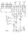
- the signal evaluation is explained in more detail with reference to FIG. 4.
- the points P 2 , P 3 ... P n to be mapped according to the measured values x 02 , y 02 , z 02 ... are entered in analog memory 4.
- the signals are passed one after the other to a coordinate transformer designated 6.
- the coordinate transformer 6 contains an internal two-dimensional coordinate transformer 7 for each rotation.
- the rotation signals ⁇ ⁇ , ⁇ are each fed to a sine and cosine converter 8, which forwards the corresponding sine or cosine signal to the internal coordinate transformers.
- the complete correction variables ⁇ x 2 , ⁇ y 2 , ⁇ z 2 of the jaw-related coordinate system X 0 , Y 0 , Z 0 are provided at the output of the coordinate transformer 6.
- the signal z 2 is evaluated with the factor a by means of a potentiometer 11. As a rule, this factor is 0.5 when viewed in perspective.
- the output signal of the addition amplifier 9 is processed with the signals x 2 , y 2 in further addition amplifiers 12 and fed to the monitor 10, on which the jaw configuration designated 13 can then be displayed and its movement can be observed.
- n points to be displayed P 2 , P 3 ... P n
- corresponding 3-n analog memories 4 are to be provided, which are then switched to the multiplexing device 5 with a specific frequency in the order of 1 to 5 kHz.
- the high switching frequency in this area compared to the movement sequence has the advantage that the movement of the points on the monitor 10 takes place practically simultaneously.
- FIG. 5 shows a perspective representation of the lower jaw model in a two-dimensional plane on a monitor 16 with an X-Y input.
- FIG. 6 shows a representation of the lower jaw model in a top view, that is to say in the XZ plane, and shows a possible course of movement for the points P 1 and P 2 in a plane perpendicular thereto, for example.
- the resulting chewing movement patterns (4 movement cycles) for points P 1 and P 2 are designated 17 and 18, respectively.
Description
Die Erfindung bezieht sich auf eine Einrichtung zur Messung des Ortes, der Lage und/oder einer Orts- bzw. Lageänderung des Unterkiefers eines Patienten in einem ostsfesten Koordinatensystem unter Verwendung eines an einem Meßpunkt angebrachten Felderzeugers, vorzugsweise eines Magnetfelderzeugers, im Abstand davon angeordneten Feldflußaufnehmern, sowie mit einer elektronischen Einrichtung zur dreidimensionalen Erfassung und Auswertung von bei einem Feldfluß bzw. einer Feldflußänderung entstehenden elektrischen Signalen.The invention relates to a device for measuring the location, the position and / or a change in position or location of the lower jaw of a patient in an east-fixed coordinate system using a field generator attached to a measuring point, preferably a magnetic field generator, with field flux sensors arranged at a distance therefrom. and with an electronic device for three-dimensional detection and evaluation of electrical signals arising during a field flow or a change in the field flow.
Eine derartige Einrichtung ist in der deutschen Patentanmeldung P 28 14 551.9 beschrieben. Die mit der dort aufgezeigten Einrichtung gewonnen Signale erfassen jedoch nur einen Punkt des Unterkiefers, nämlich den Meßpunkt, an dem der Felderzeuger befestigt ist. Die hieraus gewonnenen Signale (x1, y1, z1) entsprechen also den Koordinaten dieses einen Punktes am Unterkiefer. Zusätzlich werden mit dieser Einrichtung Informationen über eine Rotationsbewegung (α, ß, γ) um die Koordinatenachsen X, Y, Z gewonnen.Such a device is described in German patent application P 28 14 551.9. However, the signals obtained with the device shown there detect only one point of the lower jaw, namely the measuring point to which the field generator is attached. The signals obtained from this (x 1 , y 1 , z 1 ) thus correspond to the coordinates of this one point on the lower jaw. In addition, information about a rotational movement (α, β, γ) about the coordinate axes X, Y, Z is obtained with this device.
Die Darstellung eines Punktes des Unterkiefers vermittelt keine Aussage über die Lage und den Bewegungsablauf des gesamten Unterkiefers.The representation of a point of the lower jaw does not convey any information about the position and the course of movement of the entire lower jaw.
Aufgabe der Erfindung ist es, eine verbesserte Einrichtung anzugeben, insbesondere mit dem Ziel, nicht nur einen Punkt, sondern beliebig viele Punkte des Unterkiefers hinsichtlich der Lage, des Ortes und des Bewegungsverlaufes erfassen und aufzeichnen zu können.The object of the invention is to provide an improved device, in particular with the aim of being able to record and record not just one point, but any number of points of the lower jaw with regard to the position, the location and the course of movement.
Die gestellte Aufgabe wird erfindungsgemäß dadurch erzielt, daß Mittel zur Erfassung der geometrischen Lage beliebiger Punkte des Unterkiefers bezüglich eines dem Unterkiefer zugeordneten, körperfesten, Koordinatensystems, dessen Ursprung und Rotationszentrum der Meßpunkt ist, vorhanden sind, daß ein Koordinatentransformer vorhanden ist, der die unterkieferbezogenen Koordinaten in die Koordinaten des ortsfesten Koordinatensystems umrechnet, und daß Summierverstärker vorhanden sind, welche die Korrekturgrößen der kieferbezogenen Koordinaten zu den Koordinaten des Meßpunktes addieren.The object is achieved according to the invention in that means for detecting the geometrical position of any points of the lower jaw with respect to a body-fixed coordinate system assigned to the lower jaw, the origin and center of rotation of which is the measuring point, are present in that a coordinate transformer is present which coordinates the lower jaw converted into the coordinates of the stationary coordinate system, and that summing amplifiers are present which add the correction values of the jaw-related coordinates to the coordinates of the measuring point.
Vorteilhafte Ausgestaltungen und Weiterbildungen der Erfindung sind in den Unteransprüchen enthalten. Ein Ausführungsbeispiel der Erfindung wird nachfolgend anhand der Zeichnung näher erläutert. Es zeigen :
- Figur 1 eine perspektivische Darstellung eines Unterkiefers in einem Koordinatensystem,
Figur 2 eine Prinzipdarstellung zur Erläuterung der Koordinatenbeziehungen,- Figur 3 ein Kieferabdruckmodell in schaubildlicher Darstellung,
- Figur 4 ein Blockschaltbild zur Berechnung und Auswertung der Koordinaten,
- Figuren 5 und 6 zwei mögliche Bildschirmdarstellungen.
- FIG. 1 shows a perspective illustration of a lower jaw in a coordinate system,
- FIG. 2 shows a schematic diagram to explain the coordinate relationships,
- FIG. 3 shows a jaw impression model in a diagrammatic representation,
- FIG. 4 shows a block diagram for calculating and evaluating the coordinates,
- Figures 5 and 6 two possible screen displays.
Anhand der Fig. 1 wird die Relation des Meßpunktes an dem der Felderzeuger (Magnetfelderzeuger) befestigt ist zu den Flußaufnehmern erläutert. Der Meßpunkt an dem sich der Felderzeuger befindet ist mit P, bezeichnet. Der Meßpunkt P1 liegt durch die Anordnung des Felderzeugers fest und bewegt sich mit dem mit 1 bezeichneten Unterkiefer. Für die weitere Betrachtung wird P1 als im Rotationszentrum der Rotationen α, β, γ angesehen. Die Koordinaten des Meßpunktes P1 vom Koordinatennullpunkt sind mit x1, y1 und z1, bezeichnet. Die Koordinatenwerte x1, y1, z1 sowie die Rotationsinformationen aus α, β, γ werden aus der in der obengenannten Patentanmeldung beschriebenen Einrichtung geliefert. Fig. 2 gibt die Koordinatenbeziehung schematisiert für die X-Y-Ebene wieder. Die Z-Achse steht senkrecht zur Zeichenebene.1, the relation of the measuring point at which the field generator (magnetic field generator) is attached to the flow sensors is explained. The measuring point at which the field generator is located is labeled P. The measuring point P 1 is fixed by the arrangement of the field generator and moves with the lower jaw designated 1. For further consideration, P 1 is considered to be in the center of rotation of the rotations α, β, γ. The coordinates of the measuring point P 1 from the coordinate zero point are denoted by x 1 , y 1 and z 1 . The coordinate values x 1 , y 1 , z 1 and the rotation information from α, β, γ are supplied from the device described in the above-mentioned patent application. Fig. 2 shows the coordinate relationship schematically for the XY plane. The Z axis is perpendicular to the plane of the drawing.
Mit P2 ist ein beliebig am Unterkiefer 1 wählbarer Punkt bezeichnet, der zusammen mit weiteren Punkten (P3 ... Pn) bildlich dargestellt werden soll. In der Darstellung ist angenommen, daß der Unterkiefer 1 um eine zur Z-Achse parallele, durch P1 gehende Achse um den Winkel γ gedreht ist. Dem Unterkiefer 1 wird ein körperfestes Koordinatensystem Xo, Yo und Zo zugeordnet ; der Punkt P2 hat in Bezug auf dieses (kieferbezogene) Koordinatensystem die Koordination x02, y02, Unter Ausschaltung einer Rotation um den Winkel hat der Punkt P2 in Bezug auf das Koordinatensystem X, Y die Koordinaten x1 + x02 bzw. y1 + y02. Mit der in Fig. 2 dargestellten Rotation um den Winkel γ ergeben sich in Bezug auf das ortsfeste Koordinatensystem X, Y für den Punkt P2 die Korrekturgrößen Δx und Δy. Entsprechendes gilt für die Z-Achse. Das körperfeste Koordinatensystem Xo, Yo (und gegebenenfalls Zo) dient dazu, zusammen mit dem Winkel γ die relative Lage des Punktes P2 zu P1 im ortsfesten Koordinatensystem X, Y festzulegen. Bei der in Fig. 2 dargestellten Anordnung erfolgt eine Rotationsbewegung des Unterkiefers 1 um eine Achse parallel zur Z-Achse durch den Punkt P1. Zur Ermittlung der neuen Koordinaten sind hierzu die Korrekturgrößen Δx2, Δy2, Δz2 zu verwenden. Diese Korrekturgrößen werden zusammen mit den gemessenen Werten X1, Y1 und Z1 entsprechend der Formel :![]()
![]()
![]()
![]()
Für ΔZ2 ergibt sich eine Auswertung entsprechend dem nachfolgenden Blockschaltbild.For ΔZ 2 there is an evaluation according to the following block diagram.
Für den Punkt P2 ergeben sich bezüglich des ortsfesten Koordinatensystems X, Y, Z :![]()
![]()
![]()
![]()
Die Fig. 3 zeigt in einer schaubildlichen Darstellung ein Kieferabdruckmodell 2 mit dem Meßpunkt P1 in dem sich der Magnetfelderzeuger befindet. Es sei angenommen, daß die abzubildenden Punkte P2, P3 ... Pn sich auf einer mit 3 bezeichneten Mittellinie befinden sollen. Der Punkt P2 hat die Koordinatenwerte x02, y02 und z02. Diese Koordinaten werden durch geeignete Meßeinrichtungen abgenommen.3 shows a diagrammatic representation of a
Anstelle eines Abdruckmodelles kann auch ein Röntgenfilmbild verwendet werden, welches je nach der darzustellenden Punkte eine Vorder-, Seiten- oder Draufsicht des Kiefers sein kann. Die abzubildenden Punkte können entweder mit Hilfe von geeigneten Rastereinrichtungen (Millimeterpapier) oder mit Hilfe optoelektronischer Abtasteinrichtungen abgenommen werden.Instead of an impression model, an X-ray film image can also be used, which can be a front, side or top view of the jaw, depending on the points to be displayed. The points to be imaged can be removed either with the aid of suitable raster devices (graph paper) or with the aid of optoelectronic scanning devices.
Anhand der Fig. 4 wird die Signalauswertung näher erläutert. Die von den abzubildenden Punkten P2, P3 ... Pn nach den ausgemessenen Werten x02, y02, z02 ... werden in Analogspeicher 4 eingegeben. In einer Multiplexschaltung 5 werden die Signale nacheinander an einen mit 6 bezeichneten Koordinatentransformator weitergegeben. Der Koordinatentransformator 6 enthält für jede Rotation je einen internen zweidimensionalen Koordinatentransformator 7. Die Rotationssignale α β, γ werden jeweils einem Sinus-und Cosinus-Konverter 8 zugeführt, der das entsprechende Sinus- bzw. Cosinussignal an die internen Koordinatentransformatoren weitergibt. Am Ausgang des Koordinatentransformators 6 werden die vollständigen Korrekturgrößen Δx2, Δy2, Δz2 des kieferbezogenen Koordinatensystems X0, Y0, Z0 bereitgestellt. Diese Signale werden in nachfolgenden Additionsverstärkern 9 mit den gemessenen Koordinaten x1, y1, z1 des Meßpunktes P1 addiert. Am Ausgang werden die Koordinaten des Punktes P2, P3 ... Pn bezüglich des ortsfesten Koordinatensystems X, Y, Z erhalten.The signal evaluation is explained in more detail with reference to FIG. 4. The points P 2 , P 3 ... P n to be mapped according to the measured values x 02 , y 02 , z 02 ... are entered in analog memory 4. In a multiplex circuit 5, the signals are passed one after the other to a coordinate transformer designated 6. The
Für eine perspektivische Darstellung auf einem (zweidimensionalen) Monitor 10 wird das Signal z2 mittels eines Potentiometers 11 mit dem Faktor a bewertet. In der Regel beträgt dieser Faktor bei perspektivischer Darstellung 0,5. Das Ausgangssignal der Additionsverstärker 9 wird mit den Signalen x2, y2 in weiteren Additionsverstärkern 12 verarbeitet und dem Monitor 10 zugeführt, an dem dann die mit 13 bezeichnete Kieferkonfiguration dargestellt und deren Bewegung beobachtet werden kann.For a perspective representation on a (two-dimensional) monitor 10, the signal z 2 is evaluated with the factor a by means of a
Für n darzustellende Punkte (P2, P3 ... Pn) sind entsprechend 3-n Analogspeicher 4 vorzusehen, die dann der Multiplexeinrichtung 5 mit einer bestimmten Frequenz in der Größenordnung von 1 bis 5 kHz geschaltet werden. Die im Vergleich zum Bewegungsablauf hohe Schaltfrequenz in diesem Bereich hat den Vorteil, daß die Bewegung der Punkte auf dem Monitor 10 praktisch simultan erfolgen.For n points to be displayed (P 2 , P 3 ... P n ), corresponding 3-n analog memories 4 are to be provided, which are then switched to the multiplexing device 5 with a specific frequency in the order of 1 to 5 kHz. The high switching frequency in this area compared to the movement sequence has the advantage that the movement of the points on the monitor 10 takes place practically simultaneously.
Für Schulungszwecke ist es vorteilhaft den Meßpunkt P1 zu simulieren indem man die Koordinaten x1, y1, z1 und α, β, γ durch in der Darstellung nach Fig. 4 gestrichelt eingezeichneten Analogwertgeber 14 bzw. 15 ersetzt. Mit Hilfe dieser Simuliereinrichtung kann der Einfluß eines einzigen Meßwertes des Meßpunktes P1 auf die Bewegung der anderen Kieferpunkte P2, P3 ... Pn beobachtet werden.For training purposes, it is advantageous to simulate the measuring point P 1 by replacing the coordinates x 1 , y 1 , z 1 and α, β, γ by
Die Fig. 5 zeigt eine perspektivische Darstellung des Unterkiefermodells in zweidimensionaler Ebene auf einem Monitor 16 mit einem X-Y-Eingang.FIG. 5 shows a perspective representation of the lower jaw model in a two-dimensional plane on a
Die Fig. 6 zeigt eine Darstellung des Unterkiefermodells in der Draufsicht, also in der X-Z-Ebene und zeigt einen möglichen Bewegungsverlauf für die Punkte P1 und P2 in einer senkrecht dazu stehenden Ebene z. B. in der X-Y-Ebene. Die sich hieraus ergebenden Kaubewegungsmuster (4 Bewegungszyklen) für die Punkte P1 und P2 sind mit 17 bzw. 18 bezeichnet.6 shows a representation of the lower jaw model in a top view, that is to say in the XZ plane, and shows a possible course of movement for the points P 1 and P 2 in a plane perpendicular thereto, for example. B. in the XY plane. The resulting chewing movement patterns (4 movement cycles) for points P 1 and P 2 are designated 17 and 18, respectively.
Claims (10)
Applications Claiming Priority (2)
| Application Number | Priority Date | Filing Date | Title |
|---|---|---|---|
| DE19792944489 DE2944489A1 (en) | 1979-11-03 | 1979-11-03 | DEVICE FOR MEASURING THE LOCATION, LOCATION AND / OR A LOCATION OR CHANGE OF POSITION OF A PATIENT'S LOWER JAW |
| DE2944489 | 1979-11-03 |
Publications (2)
| Publication Number | Publication Date |
|---|---|
| EP0028398A1 EP0028398A1 (en) | 1981-05-13 |
| EP0028398B1 true EP0028398B1 (en) | 1983-06-01 |
Family
ID=6085109
Family Applications (1)
| Application Number | Title | Priority Date | Filing Date |
|---|---|---|---|
| EP80106652A Expired EP0028398B1 (en) | 1979-11-03 | 1980-10-29 | Device for measuring the position, the situation and/or a change in position or situation of the lower jaw of a patient |
Country Status (4)
| Country | Link |
|---|---|
| US (1) | US4386405A (en) |
| EP (1) | EP0028398B1 (en) |
| JP (1) | JPS5672844A (en) |
| DE (1) | DE2944489A1 (en) |
Families Citing this family (18)
| Publication number | Priority date | Publication date | Assignee | Title |
|---|---|---|---|---|
| US4459109A (en) * | 1981-11-25 | 1984-07-10 | Myo-Tronics Research, Inc. | Kinesiograph sensor array alignment system |
| JPS58175544A (en) * | 1982-04-07 | 1983-10-14 | 株式会社モリタ製作所 | Lower mandible motion diagnostic apparatus |
| US4528627A (en) * | 1982-11-12 | 1985-07-09 | Coben Eugene S | Method for cephalometric quantitation and expression of growth |
| US4521186A (en) * | 1983-05-17 | 1985-06-04 | Harold Wodlinger | System for determining the first prematurity contact of dental occlusion |
| DE3327742A1 (en) * | 1983-08-01 | 1985-02-14 | Siemens AG, 1000 Berlin und 8000 München | DEVICE FOR MEASURING THE LOCATION, LOCATION AND / OR LOCATION OR CHANGE OF POSITION OF A RIGID BODY IN THE SPACE |
| US4561846A (en) * | 1983-09-02 | 1985-12-31 | Denar Corporation | Dental pantograph |
| JPS62179432A (en) * | 1986-01-31 | 1987-08-06 | 坂東 永一 | Apparatus for measuring jaw motion |
| US4791934A (en) * | 1986-08-07 | 1988-12-20 | Picker International, Inc. | Computer tomography assisted stereotactic surgery system and method |
| US4837685A (en) * | 1987-02-18 | 1989-06-06 | Myo-Tronics Research, Inc. | Analog preprocessor for jaw tracking device |
| US4765345A (en) * | 1987-02-18 | 1988-08-23 | Myo-Tronics Research, Inc. | Magnetic sensor for jaw tracking device |
| US4922925A (en) * | 1988-02-29 | 1990-05-08 | Washington University | Computer based upper extremity evaluation system |
| US6152731A (en) | 1997-09-22 | 2000-11-28 | 3M Innovative Properties Company | Methods for use in dental articulation |
| US9084653B2 (en) | 1998-01-14 | 2015-07-21 | Cadent, Ltd. | Methods for use in dental articulation |
| US5989023A (en) * | 1998-12-31 | 1999-11-23 | John D. Summer | Intraoral jaw tracking device |
| US6877513B2 (en) | 2000-01-21 | 2005-04-12 | Respironics, Inc. | Intraoral apparatus for enhancing airway patency |
| DE102004015383B4 (en) * | 2004-03-26 | 2006-04-13 | SAM Präzisionstechnik GmbH | Combination device for registration of lower jaw movements with respect to the skull on the one hand and for skull-like transmission of upper jaw models in an articulator on the other |
| US8382686B2 (en) * | 2007-04-17 | 2013-02-26 | Gnath Tech Dental Systems, Llc | Apparatus and method for recording mandibular movement |
| EP3045154B1 (en) | 2008-11-25 | 2022-01-05 | Lumen Devices LLC | Medical appliance for the treatment of sleep apnea |
Family Cites Families (7)
| Publication number | Priority date | Publication date | Assignee | Title |
|---|---|---|---|---|
| US3390459A (en) * | 1959-09-17 | 1968-07-02 | Seidenberg Murray | Dental apparatus and method |
| US3822694A (en) * | 1972-10-24 | 1974-07-09 | Jankelson Bernard | Method of monitoring mandibular positions and movements |
| US3883954A (en) * | 1973-07-30 | 1975-05-20 | Threshold Tech | Method and apparatus for recording occlusal vibrations |
| DE2715106C2 (en) * | 1977-04-04 | 1982-05-27 | Siemens AG, 1000 Berlin und 8000 München | Device for measuring the location, the position and / or the change in location or position of a rigid body in space |
| DE2814551C2 (en) * | 1978-04-04 | 1986-03-13 | Siemens AG, 1000 Berlin und 8000 München | Device for measuring the location, the position and / or the change in location or position of a rigid body in space |
| JPS54136959A (en) * | 1978-04-15 | 1979-10-24 | Matsushita Electric Works Ltd | Hair curler |
| US4303919A (en) * | 1978-12-04 | 1981-12-01 | John Dimeff | Non-contacting device for sensing multi-component motion |
-
1979
- 1979-11-03 DE DE19792944489 patent/DE2944489A1/en active Granted
-
1980
- 1980-10-29 EP EP80106652A patent/EP0028398B1/en not_active Expired
- 1980-11-03 US US06/203,144 patent/US4386405A/en not_active Expired - Lifetime
- 1980-11-04 JP JP15509780A patent/JPS5672844A/en active Pending
Also Published As
| Publication number | Publication date |
|---|---|
| DE2944489C2 (en) | 1988-05-26 |
| EP0028398A1 (en) | 1981-05-13 |
| DE2944489A1 (en) | 1981-05-14 |
| JPS5672844A (en) | 1981-06-17 |
| US4386405A (en) | 1983-05-31 |
Similar Documents
| Publication | Publication Date | Title |
|---|---|---|
| EP0028398B1 (en) | Device for measuring the position, the situation and/or a change in position or situation of the lower jaw of a patient | |
| DE4225112C1 (en) | Instrument position relative to processing object measuring apparatus - has measuring device for measuring position of instrument including inertia sensor unit | |
| EP1817547B1 (en) | Method and device for navigating and positioning an object relative to a patient | |
| EP2082687B1 (en) | Overlaid presentation of exposures | |
| DE19823501B4 (en) | Device for imaging electrical activity in the heart | |
| DE4001433A1 (en) | CORRECTION PROCEDURE FOR COORDINATE MEASURING DEVICES | |
| DE19618283A1 (en) | Imaging device and method for three-dimensional non-contact measurement | |
| EP0488987A1 (en) | Method for representing moving bodies | |
| DE112010002174T5 (en) | METHOD AND DEVICE FOR A PRACTICAL 3D SEEDING SYSTEM | |
| DE19937265A1 (en) | Measuring head positioning device on a non-contact three-dimensional measuring machine has a device for determining the position of the measuring head with respect to a first reference system | |
| DE3520271A1 (en) | METHOD FOR DETERMINING THE CHANGE OF CHARACTERISTICS OF A ZONE OF A PERSON OR A TOTAL OF PERSON DEPENDING ON TIME AND DEVICE FOR CARRYING OUT THIS METHOD | |
| EP2886043A1 (en) | Method for continuing recordings to detect three-dimensional geometries of objects | |
| DE10026201A1 (en) | Device for determining the position of an object in an OXZ plane using an array of CCD cameras with a mask placed in front of them comprising an arrangement of sloping transparent and opaque bands | |
| DE102006004153B4 (en) | Automatic calibration of cooperating robots | |
| DE202019105838U1 (en) | Arrangement with a coordinate measuring machine or microscope | |
| EP1669776A1 (en) | Handheld distance measuring apparatus and a method therefore | |
| DE2649608A1 (en) | PROCEDURE FOR TRANSFERRING COORDINATE POSITIONS | |
| DE1302862B (en) | ||
| DE2259762B2 (en) | Process for the automatic evaluation of stereo images | |
| DE102009031400A1 (en) | Device and method for computer-assisted 2D navigation | |
| EP1460378A2 (en) | Method and device for tracking an object | |
| DE3324380A1 (en) | METHOD AND DEVICE FOR GENERATING IMAGES IN NUCLEAR MEDICAL CARDIOLOGICAL EXAMINATIONS | |
| DE19626889A1 (en) | Procedure for determining object geometry via multi=position 3d=sensor | |
| DE4113992A1 (en) | Automatic three=dimensional monitoring of hazardous room - using three cameras calibrated to universal standard to relate points in room to those of screen display | |
| EP2098168A1 (en) | Calibration of a C-arm x-ray device |
Legal Events
| Date | Code | Title | Description |
|---|---|---|---|
| PUAI | Public reference made under article 153(3) epc to a published international application that has entered the european phase |
Free format text: ORIGINAL CODE: 0009012 |
|
| AK | Designated contracting states |
Designated state(s): FR GB IT |
|
| RBV | Designated contracting states (corrected) |
Designated state(s): FR GB IT |
|
| 17P | Request for examination filed |
Effective date: 19811007 |
|
| ITF | It: translation for a ep patent filed |
Owner name: STUDIO JAUMANN |
|
| GRAA | (expected) grant |
Free format text: ORIGINAL CODE: 0009210 |
|
| AK | Designated contracting states |
Designated state(s): FR GB IT |
|
| EL | Fr: translation of claims filed | ||
| PLBE | No opposition filed within time limit |
Free format text: ORIGINAL CODE: 0009261 |
|
| STAA | Information on the status of an ep patent application or granted ep patent |
Free format text: STATUS: NO OPPOSITION FILED WITHIN TIME LIMIT |
|
| 26N | No opposition filed | ||
| PGFP | Annual fee paid to national office [announced via postgrant information from national office to epo] |
Ref country code: FR Payment date: 19841022 Year of fee payment: 5 |
|
| PG25 | Lapsed in a contracting state [announced via postgrant information from national office to epo] |
Ref country code: GB Effective date: 19891029 |
|
| GBPC | Gb: european patent ceased through non-payment of renewal fee | ||
| PG25 | Lapsed in a contracting state [announced via postgrant information from national office to epo] |
Ref country code: FR Effective date: 19900629 |
|
| REG | Reference to a national code |
Ref country code: FR Ref legal event code: ST |