EP0028398B1 - Einrichtung zur Messung des Ortes, der Lage und/oder einer Orts- bzw. Lageänderung des Unterkiefers eines Patienten - Google Patents
Einrichtung zur Messung des Ortes, der Lage und/oder einer Orts- bzw. Lageänderung des Unterkiefers eines Patienten Download PDFInfo
- Publication number
- EP0028398B1 EP0028398B1 EP80106652A EP80106652A EP0028398B1 EP 0028398 B1 EP0028398 B1 EP 0028398B1 EP 80106652 A EP80106652 A EP 80106652A EP 80106652 A EP80106652 A EP 80106652A EP 0028398 B1 EP0028398 B1 EP 0028398B1
- Authority
- EP
- European Patent Office
- Prior art keywords
- ordinates
- lower jaw
- points
- jaw
- represented
- Prior art date
- Legal status (The legal status is an assumption and is not a legal conclusion. Google has not performed a legal analysis and makes no representation as to the accuracy of the status listed.)
- Expired
Links
- 230000004907 flux Effects 0.000 claims description 4
- 238000001514 detection method Methods 0.000 claims description 2
- 230000005693 optoelectronics Effects 0.000 claims description 2
- 238000004088 simulation Methods 0.000 claims description 2
- 238000005259 measurement Methods 0.000 claims 5
- 238000010586 diagram Methods 0.000 description 3
- 238000011156 evaluation Methods 0.000 description 3
- 230000015654 memory Effects 0.000 description 2
- 230000001055 chewing effect Effects 0.000 description 1
- 238000011161 development Methods 0.000 description 1
- 230000018109 developmental process Effects 0.000 description 1
- 230000007717 exclusion Effects 0.000 description 1
Images

Classifications
-
- A—HUMAN NECESSITIES
- A61—MEDICAL OR VETERINARY SCIENCE; HYGIENE
- A61C—DENTISTRY; APPARATUS OR METHODS FOR ORAL OR DENTAL HYGIENE
- A61C19/00—Dental auxiliary appliances
- A61C19/04—Measuring instruments specially adapted for dentistry
- A61C19/045—Measuring instruments specially adapted for dentistry for recording mandibular movement, e.g. face bows
Definitions
- the invention relates to a device for measuring the location, the position and / or a change in position or location of the lower jaw of a patient in an east-fixed coordinate system using a field generator attached to a measuring point, preferably a magnetic field generator, with field flux sensors arranged at a distance therefrom. and with an electronic device for three-dimensional detection and evaluation of electrical signals arising during a field flow or a change in the field flow.
- the representation of a point of the lower jaw does not convey any information about the position and the course of movement of the entire lower jaw.
- the object of the invention is to provide an improved device, in particular with the aim of being able to record and record not just one point, but any number of points of the lower jaw with regard to the position, the location and the course of movement.
- the object is achieved according to the invention in that means for detecting the geometrical position of any points of the lower jaw with respect to a body-fixed coordinate system assigned to the lower jaw, the origin and center of rotation of which is the measuring point, are present in that a coordinate transformer is present which coordinates the lower jaw converted into the coordinates of the stationary coordinate system, and that summing amplifiers are present which add the correction values of the jaw-related coordinates to the coordinates of the measuring point.
- the measuring point at which the field generator (magnetic field generator) is attached to the flow sensors is labeled P.
- the measuring point P 1 is fixed by the arrangement of the field generator and moves with the lower jaw designated 1.
- P 1 is considered to be in the center of rotation of the rotations ⁇ , ⁇ , ⁇ .
- the coordinates of the measuring point P 1 from the coordinate zero point are denoted by x 1 , y 1 and z 1 .
- the coordinate values x 1 , y 1 , z 1 and the rotation information from ⁇ , ⁇ , ⁇ are supplied from the device described in the above-mentioned patent application.
- Fig. 2 shows the coordinate relationship schematically for the XY plane.
- the Z axis is perpendicular to the plane of the drawing.
- P 2 denotes a point which can be chosen arbitrarily on the lower jaw 1 and which is to be depicted together with further points (P 3 ... P n ).
- the lower jaw 1 is rotated by an angle ⁇ about an axis parallel to the Z axis and passing through P 1 .
- a rigid coordinate system X o , Y o and Z o is assigned to the lower jaw 1; the point P 2 has the coordination x 02 , y 02 in relation to this (jaw-related) coordinate system.
- the point P 2 has the coordinates x 1 + x 02 or y 1 + y 02 .
- the correction variables ⁇ x and ⁇ y result for the point P 2 in relation to the stationary coordinate system X, Y.
- the body-fixed coordinate system X o , Y o (and possibly Z o ) serves, together with the angle ⁇ , to determine the relative position of the point P 2 to P 1 in the stationary coordinate system X, Y.
- the lower jaw 1 rotates about an axis parallel to the Z axis through the point P 1 .
- the correction variables ⁇ x 2 , ⁇ y 2 , ⁇ z 2 are to be used. These correction values are calculated together with the measured values X 1 , Y 1 and Z 1 according to the formula: calculated.
- FIG. 3 shows a diagrammatic representation of a jaw impression model 2 with the measuring point P 1 in which the magnetic field generator is located. It is assumed that the points P 2 , P 3 ... P n to be imaged are to be located on a center line denoted by 3.
- the point P 2 has the coordinate values x 02 , y 02 and z 02 . These coordinates are taken by suitable measuring devices.
- an X-ray film image can also be used, which can be a front, side or top view of the jaw, depending on the points to be displayed.
- the points to be imaged can be removed either with the aid of suitable raster devices (graph paper) or with the aid of optoelectronic scanning devices.
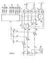
- the signal evaluation is explained in more detail with reference to FIG. 4.
- the points P 2 , P 3 ... P n to be mapped according to the measured values x 02 , y 02 , z 02 ... are entered in analog memory 4.
- the signals are passed one after the other to a coordinate transformer designated 6.
- the coordinate transformer 6 contains an internal two-dimensional coordinate transformer 7 for each rotation.
- the rotation signals ⁇ ⁇ , ⁇ are each fed to a sine and cosine converter 8, which forwards the corresponding sine or cosine signal to the internal coordinate transformers.
- the complete correction variables ⁇ x 2 , ⁇ y 2 , ⁇ z 2 of the jaw-related coordinate system X 0 , Y 0 , Z 0 are provided at the output of the coordinate transformer 6.
- the signal z 2 is evaluated with the factor a by means of a potentiometer 11. As a rule, this factor is 0.5 when viewed in perspective.
- the output signal of the addition amplifier 9 is processed with the signals x 2 , y 2 in further addition amplifiers 12 and fed to the monitor 10, on which the jaw configuration designated 13 can then be displayed and its movement can be observed.
- n points to be displayed P 2 , P 3 ... P n
- corresponding 3-n analog memories 4 are to be provided, which are then switched to the multiplexing device 5 with a specific frequency in the order of 1 to 5 kHz.
- the high switching frequency in this area compared to the movement sequence has the advantage that the movement of the points on the monitor 10 takes place practically simultaneously.
- FIG. 5 shows a perspective representation of the lower jaw model in a two-dimensional plane on a monitor 16 with an X-Y input.
- FIG. 6 shows a representation of the lower jaw model in a top view, that is to say in the XZ plane, and shows a possible course of movement for the points P 1 and P 2 in a plane perpendicular thereto, for example.
- the resulting chewing movement patterns (4 movement cycles) for points P 1 and P 2 are designated 17 and 18, respectively.
Landscapes
- Health & Medical Sciences (AREA)
- Oral & Maxillofacial Surgery (AREA)
- Life Sciences & Earth Sciences (AREA)
- Engineering & Computer Science (AREA)
- Biomedical Technology (AREA)
- Biophysics (AREA)
- Dentistry (AREA)
- Epidemiology (AREA)
- Animal Behavior & Ethology (AREA)
- General Health & Medical Sciences (AREA)
- Public Health (AREA)
- Veterinary Medicine (AREA)
- Measurement Of Length, Angles, Or The Like Using Electric Or Magnetic Means (AREA)
- Dental Tools And Instruments Or Auxiliary Dental Instruments (AREA)
- Measurement Of The Respiration, Hearing Ability, Form, And Blood Characteristics Of Living Organisms (AREA)
Applications Claiming Priority (2)
| Application Number | Priority Date | Filing Date | Title |
|---|---|---|---|
| DE19792944489 DE2944489A1 (de) | 1979-11-03 | 1979-11-03 | Einrichtung zur messung des ortes, der lage und/oder einer orts- bzw. lageaenderung des unterkiefers eines patienten |
| DE2944489 | 1979-11-03 |
Publications (2)
| Publication Number | Publication Date |
|---|---|
| EP0028398A1 EP0028398A1 (de) | 1981-05-13 |
| EP0028398B1 true EP0028398B1 (de) | 1983-06-01 |
Family
ID=6085109
Family Applications (1)
| Application Number | Title | Priority Date | Filing Date |
|---|---|---|---|
| EP80106652A Expired EP0028398B1 (de) | 1979-11-03 | 1980-10-29 | Einrichtung zur Messung des Ortes, der Lage und/oder einer Orts- bzw. Lageänderung des Unterkiefers eines Patienten |
Country Status (4)
| Country | Link |
|---|---|
| US (1) | US4386405A (OSRAM) |
| EP (1) | EP0028398B1 (OSRAM) |
| JP (1) | JPS5672844A (OSRAM) |
| DE (1) | DE2944489A1 (OSRAM) |
Families Citing this family (18)
| Publication number | Priority date | Publication date | Assignee | Title |
|---|---|---|---|---|
| US4459109A (en) * | 1981-11-25 | 1984-07-10 | Myo-Tronics Research, Inc. | Kinesiograph sensor array alignment system |
| JPS58175544A (ja) * | 1982-04-07 | 1983-10-14 | 株式会社モリタ製作所 | 下顎運動診断装置 |
| US4528627A (en) * | 1982-11-12 | 1985-07-09 | Coben Eugene S | Method for cephalometric quantitation and expression of growth |
| US4521186A (en) * | 1983-05-17 | 1985-06-04 | Harold Wodlinger | System for determining the first prematurity contact of dental occlusion |
| DE3327742A1 (de) * | 1983-08-01 | 1985-02-14 | Siemens AG, 1000 Berlin und 8000 München | Vorrichtung zur messung des ortes, der lage und/oder der orts- bzw. lageaenderung eines starren koerpers im raum |
| US4561846A (en) * | 1983-09-02 | 1985-12-31 | Denar Corporation | Dental pantograph |
| JPS62179432A (ja) * | 1986-01-31 | 1987-08-06 | 坂東 永一 | 顎運動の測定装置 |
| US4791934A (en) * | 1986-08-07 | 1988-12-20 | Picker International, Inc. | Computer tomography assisted stereotactic surgery system and method |
| US4837685A (en) * | 1987-02-18 | 1989-06-06 | Myo-Tronics Research, Inc. | Analog preprocessor for jaw tracking device |
| US4765345A (en) * | 1987-02-18 | 1988-08-23 | Myo-Tronics Research, Inc. | Magnetic sensor for jaw tracking device |
| US4922925A (en) * | 1988-02-29 | 1990-05-08 | Washington University | Computer based upper extremity evaluation system |
| US6152731A (en) * | 1997-09-22 | 2000-11-28 | 3M Innovative Properties Company | Methods for use in dental articulation |
| US9084653B2 (en) | 1998-01-14 | 2015-07-21 | Cadent, Ltd. | Methods for use in dental articulation |
| US5989023A (en) * | 1998-12-31 | 1999-11-23 | John D. Summer | Intraoral jaw tracking device |
| US6877513B2 (en) | 2000-01-21 | 2005-04-12 | Respironics, Inc. | Intraoral apparatus for enhancing airway patency |
| DE102004015383B4 (de) * | 2004-03-26 | 2006-04-13 | SAM Präzisionstechnik GmbH | Kombinationsvorrichtung zur Registrierung der Unterkieferbewegungen in Bezug auf den Schädel einerseits und zur schädelgerechten Übertragung von Oberkiefermodellen in einen Artikulator andererseits |
| US8382686B2 (en) * | 2007-04-17 | 2013-02-26 | Gnath Tech Dental Systems, Llc | Apparatus and method for recording mandibular movement |
| WO2010062952A1 (en) | 2008-11-25 | 2010-06-03 | Lumen Devices Llc | Devices, systems and methods for the treatment of sleep apnea |
Family Cites Families (7)
| Publication number | Priority date | Publication date | Assignee | Title |
|---|---|---|---|---|
| US3390459A (en) * | 1959-09-17 | 1968-07-02 | Seidenberg Murray | Dental apparatus and method |
| US3822694A (en) * | 1972-10-24 | 1974-07-09 | Jankelson Bernard | Method of monitoring mandibular positions and movements |
| US3883954A (en) * | 1973-07-30 | 1975-05-20 | Threshold Tech | Method and apparatus for recording occlusal vibrations |
| DE2715106C2 (de) * | 1977-04-04 | 1982-05-27 | Siemens AG, 1000 Berlin und 8000 München | Vorrichtung zur Messung des Ortes, der Lage und/oder der Orts- bzw. Lageänderung eines starren Körpers im Raum |
| DE2814551C2 (de) * | 1978-04-04 | 1986-03-13 | Siemens AG, 1000 Berlin und 8000 München | Vorrichtung zur Messung des Ortes, der Lage und/oder der Orts- bzw. Lageänderung eines starren Körpers im Raum |
| JPS54136959A (en) * | 1978-04-15 | 1979-10-24 | Matsushita Electric Works Ltd | Hair curler |
| US4303919A (en) * | 1978-12-04 | 1981-12-01 | John Dimeff | Non-contacting device for sensing multi-component motion |
-
1979
- 1979-11-03 DE DE19792944489 patent/DE2944489A1/de active Granted
-
1980
- 1980-10-29 EP EP80106652A patent/EP0028398B1/de not_active Expired
- 1980-11-03 US US06/203,144 patent/US4386405A/en not_active Expired - Lifetime
- 1980-11-04 JP JP15509780A patent/JPS5672844A/ja active Pending
Also Published As
| Publication number | Publication date |
|---|---|
| US4386405A (en) | 1983-05-31 |
| EP0028398A1 (de) | 1981-05-13 |
| JPS5672844A (en) | 1981-06-17 |
| DE2944489A1 (de) | 1981-05-14 |
| DE2944489C2 (OSRAM) | 1988-05-26 |
Similar Documents
| Publication | Publication Date | Title |
|---|---|---|
| EP0028398B1 (de) | Einrichtung zur Messung des Ortes, der Lage und/oder einer Orts- bzw. Lageänderung des Unterkiefers eines Patienten | |
| EP1817547B1 (de) | Verfahren und eine vorrichtung zum navigieren und positionieren eines gegenstands relativ zu einem patienten | |
| DE102011114333B4 (de) | Verfahren zur Registrierung eines Röntgenvolumens mit einem Lageerfassungssystem unter Verwendung eines Registrierphantoms | |
| EP2082687B1 (de) | Überlagerte Darstellung von Aufnahmen | |
| DE10026201A1 (de) | Vorrichtung für die Bestimmung der Position eines Gegenstandes in einem OXZ-Bezugssystem | |
| DE4001433A1 (de) | Korrekturverfahren fuer koordinatenmessgeraete | |
| DE19618283A1 (de) | Bildaufnahmevorrichtung und Verfahren für die dreidimensionale berührungsfreie Messung | |
| DE19937265A1 (de) | Verfahren und Vorrichtung zur Positionierung eines Meßkopfes auf einer kontaktfreien dreidimensionalen Meßmaschine | |
| DE3520271A1 (de) | Verfahren zum bestimmen der aenderung von charakteristika einer zone einer person oder einer person insgesamt in abhaengigkeit von der zeit und vorrichtung zur durchfuehrung dieses verfahrens | |
| DE202019105838U1 (de) | Anordnung mit einem Koordinatenmessgerät oder Mikroskop | |
| EP1669776A1 (de) | Handhaltbares Vermessungsgerät und Vermessungsverfahren für ein solches Vermessungsgerät | |
| DE2649608A1 (de) | Verfahren zum uebertragen von koordinatenstellungen | |
| DE1302862B (OSRAM) | ||
| DE102012211742B4 (de) | Verfahren zum Bestimmen eines Abstandes mittels Röntgenbildgebung und Röntgengerät | |
| EP1460378A2 (de) | Verfahren und Vorrichtung zum Ausführen einer Objektverfolgung | |
| DE3324380A1 (de) | Verfahren und geraet zur erzeugung von bildern bei nuklearmedizinischen kardiologischen untersuchungen | |
| DE102006004153B4 (de) | Automatisches Einmessen kooperierender Roboter | |
| DE19626889A1 (de) | Verfahren und Vorrichtung zur Erfassung von Geometriedaten aus unterschiedlichen Beobachtungspositionen | |
| DE4113992A1 (de) | Verfahren zur automatischen dreidimensionalen ueberwachung von gefahrenraeumen | |
| EP2098168A1 (de) | Kalibrierung eines C-Bogen-Röntgengeräts | |
| EP0563058A1 (en) | Method and sensor for the determination of the position of a position-control element relative to a reference body. | |
| DE102015013162B4 (de) | Anzuzeigende Punktsequenzdaten in Zeitreihendaten bezüglich Antriebsachsen umwandelnde Zeitreihendatenanzeigevorrichtung | |
| DE102007058293A1 (de) | Kalibriervorrichtung und Verfahren zum Abgleichen eines Roboterkoordinatensystems | |
| EP0142609A1 (de) | Vorrichtung zur Messung des Ortes, der Lage und/oder der Orts-bzw. Lageänderung eines starren Körpers im Raum | |
| DE102006005990B4 (de) | Werkstückvermessung für 3-D Lageerkennung in mehreren Multi-Roboter-Stationen |
Legal Events
| Date | Code | Title | Description |
|---|---|---|---|
| PUAI | Public reference made under article 153(3) epc to a published international application that has entered the european phase |
Free format text: ORIGINAL CODE: 0009012 |
|
| AK | Designated contracting states |
Designated state(s): FR GB IT |
|
| RBV | Designated contracting states (corrected) |
Designated state(s): FR GB IT |
|
| 17P | Request for examination filed |
Effective date: 19811007 |
|
| ITF | It: translation for a ep patent filed | ||
| GRAA | (expected) grant |
Free format text: ORIGINAL CODE: 0009210 |
|
| AK | Designated contracting states |
Designated state(s): FR GB IT |
|
| EL | Fr: translation of claims filed | ||
| PLBE | No opposition filed within time limit |
Free format text: ORIGINAL CODE: 0009261 |
|
| STAA | Information on the status of an ep patent application or granted ep patent |
Free format text: STATUS: NO OPPOSITION FILED WITHIN TIME LIMIT |
|
| 26N | No opposition filed | ||
| PGFP | Annual fee paid to national office [announced via postgrant information from national office to epo] |
Ref country code: FR Payment date: 19841022 Year of fee payment: 5 |
|
| PG25 | Lapsed in a contracting state [announced via postgrant information from national office to epo] |
Ref country code: GB Effective date: 19891029 |
|
| GBPC | Gb: european patent ceased through non-payment of renewal fee | ||
| PG25 | Lapsed in a contracting state [announced via postgrant information from national office to epo] |
Ref country code: FR Effective date: 19900629 |
|
| REG | Reference to a national code |
Ref country code: FR Ref legal event code: ST |