EP0028187B1 - Support pour carte enfichable à raccordement électrique et thermique - Google Patents
Support pour carte enfichable à raccordement électrique et thermique Download PDFInfo
- Publication number
- EP0028187B1 EP0028187B1 EP80401490A EP80401490A EP0028187B1 EP 0028187 B1 EP0028187 B1 EP 0028187B1 EP 80401490 A EP80401490 A EP 80401490A EP 80401490 A EP80401490 A EP 80401490A EP 0028187 B1 EP0028187 B1 EP 0028187B1
- Authority
- EP
- European Patent Office
- Prior art keywords
- card
- thermal
- electrical
- support
- common plane
- Prior art date
- Legal status (The legal status is an assumption and is not a legal conclusion. Google has not performed a legal analysis and makes no representation as to the accuracy of the status listed.)
- Expired
Links
Images
Classifications
-
- H—ELECTRICITY
- H01—ELECTRIC ELEMENTS
- H01R—ELECTRICALLY-CONDUCTIVE CONNECTIONS; STRUCTURAL ASSOCIATIONS OF A PLURALITY OF MUTUALLY-INSULATED ELECTRICAL CONNECTING ELEMENTS; COUPLING DEVICES; CURRENT COLLECTORS
- H01R12/00—Structural associations of a plurality of mutually-insulated electrical connecting elements, specially adapted for printed circuits, e.g. printed circuit boards [PCB], flat or ribbon cables, or like generally planar structures, e.g. terminal strips, terminal blocks; Coupling devices specially adapted for printed circuits, flat or ribbon cables, or like generally planar structures; Terminals specially adapted for contact with, or insertion into, printed circuits, flat or ribbon cables, or like generally planar structures
- H01R12/70—Coupling devices
- H01R12/7005—Guiding, mounting, polarizing or locking means; Extractors
Definitions
- the present invention relates to a support for a plug-in card with electrical and thermal connection, comprising a common flat base carrying at least one connector in the form of a bar provided with a groove for receiving an edge of the card, the internal faces of a groove arranged opposite, carrying on the one hand electrical contacts and on the other thermal contacts in connection with a cooling member.
- Printed cards used in plug-in circuits use increasingly large electrical powers and the problem of heat dissipation of the heat produced by the Joule effect arises.
- the support according to the invention proposes to solve the problem posed by the evacuation of the calories generated by the circuits with high heat dissipation which are arranged on printed boards provided with a thermal drain as described in the German application cited above. .
- the support for a plug-in card is characterized in that the connecting element is a thermal conductor supported by the bar and in that the cooler organ is formed by the plan comman base.
- Fig. 1 shows a support with electrical and thermal connection, of known type, for circuit on card.
- the support comprises a base 1, on which are fixed connectors in the form of a barrett such as 2.
- Each bar comprises a groove with two opposite faces, 3 and 4, intended to receive an edge 5 of a circuit on a card 6.
- One of the faces 3 of the groove is intended to ensure the electrical connection with the electrical circuit 7 carried by the card 6, and carries contact elements such as 8, endowed with elasticity by their material and their shape.
- the second face 4 of the groove carried by the bar 2 is mobile, and can pivot around the point 9.
- the card In the open position, it is easy to introduce the card, the position of which is defined by the stops 26 and 11, and the closed position, as shown in the figure, applies the card to the stop 11, and simultaneously compresses the contact 8 which bends by elasticity thanks to its part 20 and makes the electrical connection with the necessary bearing force.
- a connection tab 21 allows connection with external circuits.
- the thermal face 4 of the strip carries thermal contacts such as 22, made of material which is a good conductor of heat, and conveying the thermal energy to be eliminated thanks to a suitable surface section, by a transmission tab such as 23, in relationship with a cooler 24 provided with fins 25, and operating by air convection.
- Such a connector operates as follows: the two faces 3 and 4 of the bar 2 are movable relative to each other, by rotation about the axis 9. In the phase of placing the card , the connector is open, the face 4 forms an angle which releases the face 3, and the introduction of the card 6 is carried out, positioned transversely by the stop 26.
- the electrical contact occupies position 27, shown in dashes.
- the card consists of two superimposed layers, an electrically insulating layer or substrate 6, carrying the electrical circuit 7 and its connection regions, and a layer 28 made of material with good thermal conduction, such as a metal for example, a layer often designated. under the term of thermal drain.
- the connector closes, as shown in the figure, and the thermal contact 22 is applied to the surface of the drain.
- the electrical contact 8 is pushed back and takes, by elasticity, the shape shown in solid lines in the figure.
- the bearing force necessary for good thermal conduction between the drain 28 and the contact 22 is obtained by the elastic force provided by the electrical contact which makes it vis-a-vis.
- a second stopper II parallel to the direction of installation of the card, fixes the amplitude of this to avoid that, by excessive compression of the contact, the elastic limit is not exceeded.
- the introduction of the card can be effected by a sliding parallel to the grooves, or a translation perpendicular to the latter.
- This support of known type is not satisfactory for the evacuation of the calories generated by circuits with high heat dissipation.
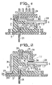
- Fig. 2 shows an embodiment of the support of the invention, with conduction cooling.
- the card is put in place by a translational movement perpendicular to the plane of the card.
- the external part 30 of the cooler no longer has fins, and it only assumes the function of thermal conduction, in the direction of the arrows such as 31 from the thermal drain 28, towards the base 1, comprising an insulating layer 33 and a thermal drain base 34, made of thermally good conductive material.
- a fixing means such as screws 35 ensures satisfactory obtaining of the two desired types of contact.
- the thermal drain 28 of the card 6 is directed upwards in the figure, the thermal contacts of the support according to the invention also being arranged on the top, so that there is an evacuation of the calories present on the thermal drain 28 to the base heat sink 34 via a thermal conductive connecting element 30, said element being supported by the bar 2.
- the support comprises four bars arranged on the common plane base according to a four-color rectangle.
- the connector of the invention ensures satisfactory results as described above, it may be advantageous to improve the thermal transmission at the points of contact of departure and arrival of the thermal conductor by interposing a product there. fluid, pasty or plastic, based on silicones for example, in 36 and 37, which dispenses with too precise surface machining between the corresponding contact regions.
Landscapes
- Coupling Device And Connection With Printed Circuit (AREA)
- Cooling Or The Like Of Electrical Apparatus (AREA)
- Multi-Conductor Connections (AREA)
- Mounting Of Printed Circuit Boards And The Like (AREA)
Applications Claiming Priority (2)
| Application Number | Priority Date | Filing Date | Title |
|---|---|---|---|
| FR7926613 | 1979-10-26 | ||
| FR7926613A FR2469019A1 (fr) | 1979-10-26 | 1979-10-26 | Support pour carte enfichable a raccordement electrique et thermique |
Publications (2)
| Publication Number | Publication Date |
|---|---|
| EP0028187A1 EP0028187A1 (fr) | 1981-05-06 |
| EP0028187B1 true EP0028187B1 (fr) | 1984-05-16 |
Family
ID=9231082
Family Applications (1)
| Application Number | Title | Priority Date | Filing Date |
|---|---|---|---|
| EP80401490A Expired EP0028187B1 (fr) | 1979-10-26 | 1980-10-21 | Support pour carte enfichable à raccordement électrique et thermique |
Country Status (6)
| Country | Link |
|---|---|
| US (1) | US4314311A (OSRAM) |
| EP (1) | EP0028187B1 (OSRAM) |
| JP (1) | JPS5673500A (OSRAM) |
| CA (1) | CA1170780A (OSRAM) |
| DE (1) | DE3067879D1 (OSRAM) |
| FR (1) | FR2469019A1 (OSRAM) |
Families Citing this family (31)
| Publication number | Priority date | Publication date | Assignee | Title |
|---|---|---|---|---|
| FR2477828A1 (fr) * | 1980-03-07 | 1981-09-11 | Thomson Csf Mat Tel | Systeme d'interconnexion electrique et thermique pour des cartes a circuits electroniques, et armoire electrique equipee d'un tel systeme |
| DE3020902A1 (de) * | 1980-06-02 | 1981-12-17 | Robert Bosch Gmbh, 7000 Stuttgart | Elektronisches steuergeraet, insbesondere fuer kraftfahrzeuge |
| EP0054092B1 (fr) * | 1980-12-12 | 1985-10-09 | Socapex | Connecteur électrique et thermique pour cartes comportant des moyens de conduction électrique et thermique, ainsi que fiche de connexion électrique et thermique enfichable dans un tel connecteur |
| FR2524203B1 (fr) * | 1982-03-26 | 1985-09-13 | Socapex | Systeme de connexion electrique et d'evacuation de la chaleur par conduction de composants electroniques |
| FR2524205B1 (fr) * | 1982-03-26 | 1985-10-04 | Socapex | Connecteur de micro-boitier ceramique a connexions perimetriques et systeme de connexion electrique et thermique utilisant un tel connecteur |
| EP0090714B1 (fr) * | 1982-03-26 | 1989-11-29 | Socapex | Système de connexion électrique et d'évacuation de la chaleur par conduction de composants électroniques |
| FR2524204A1 (fr) * | 1982-03-26 | 1983-09-30 | Socapex | Connecteur pour substrat et systeme de connexion electrique et de refroidissement par convection utilisant un tel connecteur |
| DE3245072A1 (de) * | 1982-12-06 | 1984-06-07 | Siemens AG, 1000 Berlin und 8000 München | Thermische steckverbindung |
| US4530554A (en) * | 1983-12-27 | 1985-07-23 | Northern Telecom Limited | High density low profile multiple contact connector |
| DE3430591A1 (de) * | 1984-08-20 | 1986-02-27 | Precitronic Gesellschaft für Feinmechanik und Electronic mbH, 2000 Hamburg | Kontaktgabeeinrichtung zwischen einem geraet und einem verbrauchsartikel |
| US5161087A (en) * | 1990-10-15 | 1992-11-03 | International Business Machines Corporation | Pivotal heat sink assembly |
| US5079567A (en) * | 1991-03-04 | 1992-01-07 | Eastman Kodak Company | Leaf-spring assembly for LED printhead |
| US5511985A (en) * | 1994-06-16 | 1996-04-30 | Burndy Corporation | Angled card edge connector |
| DE19532330A1 (de) * | 1995-09-01 | 1997-03-06 | Teves Gmbh Alfred | Sensor-Haltebaugruppe, insbesondere für Drehzahlsensoren |
| US6055158A (en) * | 1999-03-16 | 2000-04-25 | Framatome Connectors Interlock, Inc. | Electronic component heat sink assembly |
| JP2001185307A (ja) * | 1999-12-28 | 2001-07-06 | Jst Mfg Co Ltd | モジュール用コネクタ |
| JP2001185306A (ja) | 1999-12-28 | 2001-07-06 | Jst Mfg Co Ltd | モジュール用コネクタ |
| GB2436170A (en) * | 2006-03-17 | 2007-09-19 | Amstrad Plc | Cooling or heating device in a chip card reader |
| DE102007055235B3 (de) * | 2007-11-20 | 2009-06-10 | Continental Automotive Gmbh | Elektrischer Steckkontakt eines elektrischen Antriebssystems |
| DE102007055320B3 (de) * | 2007-11-20 | 2009-03-05 | Continental Automotive Gmbh | Elektrischer Steckkontakt eines elektrischen Antriebssystems |
| GB2463745A (en) * | 2008-04-03 | 2010-03-31 | Bosch Gmbh Robert | Electric spring contact on pin of sealed module mechanically urges module towards heatsink |
| DE102009001823A1 (de) * | 2008-04-03 | 2009-10-08 | Robert Bosch Gmbh | Elektrische Anordnung als Entwärmungskonzept |
| DE102011013711B3 (de) * | 2011-03-11 | 2012-05-24 | Amphenol-Tuchel Electronics Gmbh | Hochstromstecker |
| DE102015212660B4 (de) * | 2015-07-07 | 2020-10-08 | Volkswagen Aktiengesellschaft | Ladestecker |
| JP6625004B2 (ja) * | 2016-04-14 | 2019-12-25 | キヤノン株式会社 | カード型記録装置およびスロット装置 |
| CN113036487B (zh) * | 2017-07-28 | 2022-06-24 | 富士康(昆山)电脑接插件有限公司 | 卡缘连接器 |
| US20220007493A1 (en) * | 2018-11-01 | 2022-01-06 | Reflex Photonics, Inc. | Heat dissipation from active devices connected to connectors |
| CN111521214B (zh) * | 2020-05-06 | 2022-01-21 | 山东交通学院 | 一种工程机械电气设备检测装置 |
| DE102020208113B4 (de) | 2020-06-30 | 2022-04-28 | Yamaichi Electronics Deutschland Gmbh | Leiterplattenhalterung mit Kühlelement und System umfassend eine Leiterplattenhalterung und eine Leiterplatte |
| CN116131010A (zh) * | 2022-12-29 | 2023-05-16 | 联想(北京)有限公司 | 一种连接结构、电子设备及控制方法 |
| EP4576441A1 (de) * | 2023-12-18 | 2025-06-25 | Hilti Aktiengesellschaft | Elektrische steckverbinderanordnung |
Family Cites Families (6)
| Publication number | Priority date | Publication date | Assignee | Title |
|---|---|---|---|---|
| US3506878A (en) * | 1968-09-26 | 1970-04-14 | Hughes Aircraft Co | Apparatus for mounting miniature electronic components |
| US3550681A (en) * | 1968-12-30 | 1970-12-29 | Gen Motors Corp | Self-adjusting thermal connector |
| US3631325A (en) * | 1970-06-15 | 1971-12-28 | Sperry Rand Corp | Card module and end wall treatment facilitating heat transfer and sliding |
| GB1544651A (en) * | 1976-10-29 | 1979-04-25 | Secr Defence | Edge connectors |
| US4063791A (en) * | 1976-12-27 | 1977-12-20 | Cutchaw John M | Connector for leadless integrated circuit packages |
| US4082407A (en) * | 1977-05-20 | 1978-04-04 | Amerace Corporation | Terminal block with encapsulated heat sink |
-
1979
- 1979-10-26 FR FR7926613A patent/FR2469019A1/fr active Granted
-
1980
- 1980-04-08 US US06/138,319 patent/US4314311A/en not_active Expired - Lifetime
- 1980-10-21 EP EP80401490A patent/EP0028187B1/fr not_active Expired
- 1980-10-21 DE DE8080401490T patent/DE3067879D1/de not_active Expired
- 1980-10-23 CA CA000363130A patent/CA1170780A/fr not_active Expired
- 1980-10-27 JP JP14950480A patent/JPS5673500A/ja active Pending
Non-Patent Citations (1)
| Title |
|---|
| IBM TECHNICAL DISCLOSURE BULLETIN, vol. 20, nr. 11A, avril 1978 New York US P.W. HARDIN: "Integral edge connector", pages 4346-4348 * |
Also Published As
| Publication number | Publication date |
|---|---|
| CA1170780A (fr) | 1984-07-10 |
| FR2469019A1 (fr) | 1981-05-08 |
| JPS5673500A (en) | 1981-06-18 |
| DE3067879D1 (en) | 1984-06-20 |
| EP0028187A1 (fr) | 1981-05-06 |
| FR2469019B1 (OSRAM) | 1983-03-04 |
| US4314311A (en) | 1982-02-02 |
Similar Documents
| Publication | Publication Date | Title |
|---|---|---|
| EP0028187B1 (fr) | Support pour carte enfichable à raccordement électrique et thermique | |
| EP0308296B1 (fr) | Circuit imprimé équipé d'un drain thermique | |
| US4483389A (en) | Telescoping thermal conduction element for semiconductor devices | |
| EP0407957B1 (fr) | Dispositif de dissipation thermique pour composant de type cms monté sur plaque de circuit imprimé | |
| FR2773275A1 (fr) | Connecteur electrique de tres faible epaisseur pour le raccordement d'une carte a memoire electronique | |
| EP0145542B1 (fr) | Connecteur à force d'insertion nulle pour support rectangulaire de circuit, et pince de fermeture pour un tel connecteur | |
| EP0034081B1 (fr) | Barrette de connexion pour carte enfichable, et connecteur muni de telles barrettes | |
| WO2000041448A1 (fr) | Module electronique comportant des elements de refroidissement de composants electroniques | |
| US5945905A (en) | High power resistor | |
| US4213112A (en) | Variable resistance potentiometer | |
| EP1304912B1 (fr) | Dispositif de maintien d'au moins deux composants électroniques disposés en vis-à-vis de part et d'autre d'une carte de connexion | |
| EP0748511B1 (en) | Thermistor | |
| EP1792526A1 (fr) | Dispositif electronique avec repartiteur de chaleur integre | |
| US3747044A (en) | Microwave integrated circuit (mic) ground plane connector | |
| FR2741503A1 (fr) | Agencement de plusieurs composants electriques disposes dans un boitier | |
| FR2693031A1 (fr) | Dispositif à semiconducteurs, substrat et cadre de montage pour ce dispositif. | |
| FR2511193A1 (fr) | Support en materiau colamine pour le refroidissement et l'encapsulation d'un substrat de circuit electronique | |
| FR2581250A1 (fr) | Appareil et procede pour etablir une liaison thermique entre un boitier de semi-conducteur et la plaque de refroidissement et une liaison electrique entre les conducteurs du boitier, et un panneau de circuit imprime | |
| EP0700084A1 (fr) | Dispositif de fixation de composants électroniques de puissance contre un dissipateur et procédé de montage sur un circuit imprimé | |
| US6016085A (en) | Flat cable load | |
| EP0054092A1 (fr) | Connecteur électrique et thermique pour cartes comportant des moyens de conduction électrique et thermique, ainsi que fiche de connexion électrique et thermique enfichable dans un tel connecteur | |
| EP1371113B1 (fr) | Connecteur de puissance pour circuit imprime | |
| EP0091847B1 (fr) | Connecteur pour substrat et système de connexion électrique et de refroidissement par convection utilisant un tel connecteur | |
| FR2471059A1 (fr) | Connecteur electrique du genre de ceux pour cartes comportant des conducteurs imprimes ou graves ainsi que fiche de connexion electrique enfichable dans un tel connecteur | |
| EP4262323A1 (fr) | Table de cuisson et procédé d'assemblage de la table de cuisson |
Legal Events
| Date | Code | Title | Description |
|---|---|---|---|
| PUAI | Public reference made under article 153(3) epc to a published international application that has entered the european phase |
Free format text: ORIGINAL CODE: 0009012 |
|
| AK | Designated contracting states |
Designated state(s): DE GB IT |
|
| 17P | Request for examination filed |
Effective date: 19810624 |
|
| ITF | It: translation for a ep patent filed | ||
| RBV | Designated contracting states (corrected) |
Designated state(s): DE GB IT |
|
| GRAA | (expected) grant |
Free format text: ORIGINAL CODE: 0009210 |
|
| AK | Designated contracting states |
Designated state(s): DE GB IT |
|
| REF | Corresponds to: |
Ref document number: 3067879 Country of ref document: DE Date of ref document: 19840620 |
|
| PLBE | No opposition filed within time limit |
Free format text: ORIGINAL CODE: 0009261 |
|
| STAA | Information on the status of an ep patent application or granted ep patent |
Free format text: STATUS: NO OPPOSITION FILED WITHIN TIME LIMIT |
|
| 26N | No opposition filed | ||
| PGFP | Annual fee paid to national office [announced via postgrant information from national office to epo] |
Ref country code: GB Payment date: 19901001 Year of fee payment: 11 |
|
| PGFP | Annual fee paid to national office [announced via postgrant information from national office to epo] |
Ref country code: DE Payment date: 19901026 Year of fee payment: 11 |
|
| ITTA | It: last paid annual fee | ||
| PG25 | Lapsed in a contracting state [announced via postgrant information from national office to epo] |
Ref country code: GB Effective date: 19911021 |
|
| GBPC | Gb: european patent ceased through non-payment of renewal fee | ||
| PG25 | Lapsed in a contracting state [announced via postgrant information from national office to epo] |
Ref country code: DE Effective date: 19920701 |