EP0027772A1 - Perfectionnements apportés aux appareils de décapage du type à support télescopique et à treuil de manoeuvre - Google Patents
Perfectionnements apportés aux appareils de décapage du type à support télescopique et à treuil de manoeuvre Download PDFInfo
- Publication number
- EP0027772A1 EP0027772A1 EP80420112A EP80420112A EP0027772A1 EP 0027772 A1 EP0027772 A1 EP 0027772A1 EP 80420112 A EP80420112 A EP 80420112A EP 80420112 A EP80420112 A EP 80420112A EP 0027772 A1 EP0027772 A1 EP 0027772A1
- Authority
- EP
- European Patent Office
- Prior art keywords
- winch
- drums
- support
- cables
- telescopic
- Prior art date
- Legal status (The legal status is an assumption and is not a legal conclusion. Google has not performed a legal analysis and makes no representation as to the accuracy of the status listed.)
- Withdrawn
Links
- 238000004140 cleaning Methods 0.000 title abstract 2
- XLYOFNOQVPJJNP-UHFFFAOYSA-N water Substances O XLYOFNOQVPJJNP-UHFFFAOYSA-N 0.000 claims abstract 3
- 230000000694 effects Effects 0.000 claims abstract 2
- 230000005540 biological transmission Effects 0.000 claims 3
- 239000000725 suspension Substances 0.000 claims 2
- 238000006073 displacement reaction Methods 0.000 claims 1
- 238000005554 pickling Methods 0.000 claims 1
- 230000000717 retained effect Effects 0.000 claims 1
- 238000006467 substitution reaction Methods 0.000 claims 1
Images

Classifications
-
- B—PERFORMING OPERATIONS; TRANSPORTING
- B08—CLEANING
- B08B—CLEANING IN GENERAL; PREVENTION OF FOULING IN GENERAL
- B08B9/00—Cleaning hollow articles by methods or apparatus specially adapted thereto
- B08B9/08—Cleaning containers, e.g. tanks
- B08B9/093—Cleaning containers, e.g. tanks by the force of jets or sprays
- B08B9/0936—Cleaning containers, e.g. tanks by the force of jets or sprays using rotating jets
Definitions
- the present invention relates to stripping machines with rotating jets used for the hydraulic cleaning of the internal wall of tanks, reservoirs or other capacities, and it relates more particularly to those which are associated with a support that is orientable and arranged telescopically in order to allow adjustment of the exact position of the rotating working member within the capacity concerned.
- Apparatuses of this type are already known which are equipped with a light winch for maneuvering, most often manual, of the telescopic support.
- Such a construction cannot however be suitable if it is intended to produce a stripping apparatus at high power, fixed to the base of a telescopic support of considerable height; in fact in such a case the weight of the assembly would be too great to be operated by hand, and if it were intended to provide such a winch with an engine, this would lead to unacceptable bulk and serious difficulties.
- the improvements which are the subject of the present invention are more specifically intended to allow the construction of a high performance pickling apparatus, provided with a telescopic support capable of being maneuvered in an easy and safe manner.
- the apparatus according to the invention is characterized in that the maneuvering winch comprises two separate drums on which are wound in a spiral, in opposite directions, two suspension cables arranged in the known manner, on either side another of the flexible pipe for supplying water under pressure, these two drums being connected to a motor to rotate in opposite directions.
- the winch is made to comprise a rotating roller mechanism which is driven through a friction device capable of slipping so as to tend to impart a speed to the flexible water supply pipe. of scrolling greater than that of the two cables, so that the revolving jet device suspended from said cables and connected to the above-mentioned flexible pipe is positively pushed down when it descends inside the capacity to be cleaned.
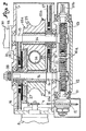
- the apparatus shown in fig. 1 comprises, in the manner known per se, a stripping device 1 of the rotating jet type, fixed to the lower end of a suitable support.
- the latter comprises in the first place a series of tubular elements 2 fitted telescopically one inside the others, and surmounted by a spherical part 3 capable of being oriented relative to a ring 4 intended to bear against the edge of the opening of a tank such as 5.
- the abovementioned support further comprises a sheath 6 upwards on which is fixed the frame or casing 7 which contains the organs of the maneuvering winch.
- this winch comprises a motor 8, with pneumatic drive in the embodiment considered, whose output shaft is connected by a chain transmission 9 to a horizontal shaft 10: it will be noted that with the transmission 9 is associated a torque limiting device 11 of the usual type.
- the shaft 10 carries two threaded parts 10a whose threads are oriented in opposite directions, each of said parts 10a cooperating with a corresponding wheel 12, 13, wedged on a transverse shaft 14, 15 suitably supported in the frame 7.
- the shaft 10 is advantageously provided with a nozzle 10b allowing the manual drive of the winch if necessary.
- each of the shafts 14 and 15 is wedged a drum 16, respectively 17, the hub of which is made integral with the end of a cable 18, 19 ; the side cheeks of these two drums are very close together so that the turns of the cables stack radially on top of each other without axial offset.
- this sheath 6 contains a tube 21 with a square section which thus defines four housings in said sheath, each of which has a segment-shaped profile.
- two opposite housings are crossed by cables 18 and 19, while the other two are occupied by two conduits 22 which supply compressed air to the device; (intake and evacuation).
- the cables 18 and 19, as well as the conduits 22, arranged telescopically in order to conform to the modifications in length of the elements 2 of the support are held by rings 23 which operate the retaining and guiding of said elements, the tank upper allowing the connection between the tube 21 and the element 2 with a larger diameter, while the lower ring, to which the lower end of the cables 18 and 19 is attached, is permanently fixed to the device 1.
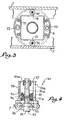
- transverse shafts 14 and 15 which drive the drums 16 and 17 are provided with an axial lining 24 (fig. 2) each of which forms a support for an idler roller 25.
- Each roller 25 is hollowed out with a groove to be applied against the flexible pipe 26 which supplies the device 1 with pressurized water.
- This pipe 26 passes vertically through the winch, its upper end being connected to a suitable source, and it engages axially in the sheath 6, in the square tube 21 and in the telescopic elements 2 to connect to the rotating jets of the device 1.
- the roller mechanism 25 is driven from the drum 16.
- one of the lateral faces of the latter is integral with a friction disc 27 which is kept elastically applied, under the effect of deformable washers 28 mounted. at the end of the shaft 14, against the blank of a toothed wheel 29 supported by the lining 24 of said shaft.
- This wheel 29 meshes with a toothing 25a provided laterally on that of the rollers 25 which is mounted on the shaft 15 of the drum 17; the two rollers 25 are linked to each other by lateral teeth 25b engaged with each other, said teeth being identical so that the two rollers rotate at the same speed.
- this device 30 comprises a nut 31 screwed, with the interposition of a row of balls 32, on the threaded end 15a of the shaft 15 which penetrates into a cylindrical protection sleeve 33 fitted against the rear wall of the casing 7
- This nut 31 is angularly retained in the sleeve 33 (for example and as shown by means of a ball 34 engaged partly in a blind cylindrical housing of said nut and partly in a longitudinal slide 33a of the aforementioned sleeve) and it is equipped on each of its axial faces with a needle bearing 35 intended to come to bear for one against a shoulder associated with the bearing 36 which supports the shaft 15, for the other against a cap 37 fixed in an easily interchangeable manner end of said tree.
- the assembly formed by the winch, the support and the pickling device is first installed on the opening or manhole of the tank 5 to be cleaned; for this purpose the lower part of the aforementioned assembly is engaged in the tank so that the ring 4 comes to bear against the edge of the opening, then the ball joint 3 is maneuvered until bringing the general axis of the support and the device at the desired orientation and inclination, and finally said ball joint is locked, in known manner, in the retaining position.
- the pipe 26 and the upper outlet of the telescopic pipes 22 are suitably connected to the corresponding fixed installations.
- the motor 8 is started in the direction corresponding to the descent, which results in unwinding cables 18 and 19 from drums 16 and 17 and drive the rotary roller mechanism in rotation 25.
- the telescopic elements 2 of the support deploy downward during the progressive descent of the device 2, this descent taking place by gravity and as a result of the thrust action exerted by the flexible pipe 26 on said device ; indeed the roller mechanism 25 tends to impart to this pipe a running speed higher than that of the cables 18 and 19 the friction drive system 27-29 authorizing a compensation compensation due to the elasticity introduced into said system by the deformable washers 28.
- the safety device 30 opposes any risk of damage to the winch and to the device 1 in the event that, as a result of an oversight, the operator does not stop the engine 8 at one or the other. other of the two ends of the race. It is in fact understood that, as a result of its angular immobilization, the nut 31 of this device 30 moves axially in one direction or the other depending on the direction of rotation of the shaft 15.
- the upper end of travel corresponding to the support of the nut 31 against the shoulder associated with the bearing 36, is adjusted in the factory taking into account the fixing of the ends of the cables on the drums 16 and 17; on the other hand, the lower end of travel, obtained by pressing the nut 31 against the cap 37, is capable of being modified as a function of the depth of the tank 5 considered, by replacing said cap with another having a different axial length .
- the limiter torque 11, associated with the chain wheel of the transmission 9 intervenes to automatically unload the motor R when the nut 31 comes to a stop at one or the other of the two ends of its travel while opposing any rotation subsequent of the shaft 15 and of the two drums 16 and 17.
- the sliding nut 31 is advantageously provided with a lateral finger 31a (fig. 4) which moves inside a light 33b cut longitudinally in the sleeve 33, so that the operator can at any moment check the axial position of said nut, position which obviously corresponds to an equivalent position of the device 1 inside the tank.
- the light 33b carries along one of its edges a series of marks which make it possible to very precisely adjust the positioning of the rotating working jets of the device 1 in the tank 5.
Landscapes
- Engineering & Computer Science (AREA)
- Mechanical Engineering (AREA)
- Cleaning In General (AREA)
Applications Claiming Priority (2)
| Application Number | Priority Date | Filing Date | Title |
|---|---|---|---|
| FR7926461A FR2467660A1 (fr) | 1979-10-19 | 1979-10-19 | Perfectionnements apportes aux appareils de decapage du type a support telescopique et a treuil de manoeuvre |
| FR7926461 | 1979-10-19 |
Publications (1)
| Publication Number | Publication Date |
|---|---|
| EP0027772A1 true EP0027772A1 (fr) | 1981-04-29 |
Family
ID=9231013
Family Applications (1)
| Application Number | Title | Priority Date | Filing Date |
|---|---|---|---|
| EP80420112A Withdrawn EP0027772A1 (fr) | 1979-10-19 | 1980-10-14 | Perfectionnements apportés aux appareils de décapage du type à support télescopique et à treuil de manoeuvre |
Country Status (2)
| Country | Link |
|---|---|
| EP (1) | EP0027772A1 (en:Method) |
| FR (1) | FR2467660A1 (en:Method) |
Cited By (1)
| Publication number | Priority date | Publication date | Assignee | Title |
|---|---|---|---|---|
| WO1991016150A1 (en) * | 1990-04-25 | 1991-10-31 | Toftejorg A/S | Cleaning equipment, especially for the cleaning of a tank |
Citations (2)
| Publication number | Priority date | Publication date | Assignee | Title |
|---|---|---|---|---|
| US2785008A (en) * | 1955-11-18 | 1957-03-12 | Arthur R Young | Tank-cleaning device |
| CH476533A (fr) * | 1968-03-01 | 1969-08-15 | Battelle Memorial Inst Interna | Installation pour laver intérieurement une citerne |
-
1979
- 1979-10-19 FR FR7926461A patent/FR2467660A1/fr active Granted
-
1980
- 1980-10-14 EP EP80420112A patent/EP0027772A1/fr not_active Withdrawn
Patent Citations (2)
| Publication number | Priority date | Publication date | Assignee | Title |
|---|---|---|---|---|
| US2785008A (en) * | 1955-11-18 | 1957-03-12 | Arthur R Young | Tank-cleaning device |
| CH476533A (fr) * | 1968-03-01 | 1969-08-15 | Battelle Memorial Inst Interna | Installation pour laver intérieurement une citerne |
Cited By (1)
| Publication number | Priority date | Publication date | Assignee | Title |
|---|---|---|---|---|
| WO1991016150A1 (en) * | 1990-04-25 | 1991-10-31 | Toftejorg A/S | Cleaning equipment, especially for the cleaning of a tank |
Also Published As
| Publication number | Publication date |
|---|---|
| FR2467660B1 (en:Method) | 1983-02-18 |
| FR2467660A1 (fr) | 1981-04-30 |
Similar Documents
| Publication | Publication Date | Title |
|---|---|---|
| EP0344028B1 (fr) | Dispositif et procédé de vissage et de dévissage d'un écrou sur un élément de liaison | |
| CA2763974C (fr) | Dispositif de reglage de largeur pour couloir(s) de convoyeur. | |
| CA1080190A (fr) | Methode et dispositif de rangement automatique d'un element allonge flexible dans un panier tournant d'axe vertical | |
| FR2502667A1 (fr) | Mecanisme d'avance pour furet de plombier a moteur | |
| EP0362013B1 (fr) | Dispositif de vissage et de dévissage d'au moins un écrou sur des éléments de liaison | |
| CA2645088A1 (fr) | Antidevireur a ressort | |
| EP0027772A1 (fr) | Perfectionnements apportés aux appareils de décapage du type à support télescopique et à treuil de manoeuvre | |
| EP0935584B1 (fr) | Broche de vissage a couple de serrage reglable | |
| EP0592325A1 (fr) | Appareil pour creuser dans le sol des tranchées de grande profondeur à l'aide de tambours de fraisage montés sur un châssis | |
| EP1916040A2 (fr) | Dispositif de lavage de tubes, en particulier de tubes de faisceaux d'échangeurs de chaleur | |
| FR2743359A1 (fr) | Treuil pour un element flexible continu | |
| EP0342120A1 (fr) | Dispositif de brossage du plan de joint d'un trou d'homme prévu pour l'accès à l'intérieur d'une cuve | |
| EP1491713B1 (fr) | Engrenage à roue et vis sans fin tangente pour volet roulant | |
| EP1932042B1 (fr) | Machine de pose de cable optique autour d'un cable porteur | |
| EP1028005A1 (fr) | Machine de marquage à bras radial | |
| FR2813299A1 (fr) | Treuil pour une roue de secours d'un vehicule | |
| EP0122198B1 (fr) | Porte-mine pour machine à dessiner | |
| FR2506277A1 (fr) | Dispositif de trancannage et girouettage, en particulier pour le flexoforage | |
| FR2584317A1 (fr) | Dispositif nettoyeur, utilisable notamment entre les tubes d'un faisceau de tubes | |
| FR2977172A1 (fr) | Dispositif de manoeuvre d'un flexible | |
| EP0122181B1 (fr) | Machine pour la mise en état et/ou l'entretien des sols | |
| EP0263763B1 (fr) | Machine pour la préparation automatique des extrémités à raccorder des tuyaux souples en caoutchouc armé | |
| FR2650580A3 (fr) | Palan manuel | |
| FR2550845A1 (fr) | Appareil de signalisation du passage d'un piston racleur dans une canalisation | |
| WO2007031506A2 (fr) | Machine de pose de cable optique automotrice |
Legal Events
| Date | Code | Title | Description |
|---|---|---|---|
| PUAI | Public reference made under article 153(3) epc to a published international application that has entered the european phase |
Free format text: ORIGINAL CODE: 0009012 |
|
| AK | Designated contracting states |
Designated state(s): AT BE CH DE GB IT NL SE |
|
| 17P | Request for examination filed |
Effective date: 19810713 |
|
| STAA | Information on the status of an ep patent application or granted ep patent |
Free format text: STATUS: THE APPLICATION IS DEEMED TO BE WITHDRAWN |
|
| 18D | Application deemed to be withdrawn |
Effective date: 19830121 |