EP0026222B1 - Bayonet type lens mounting - Google Patents
Bayonet type lens mounting Download PDFInfo
- Publication number
- EP0026222B1 EP0026222B1 EP80900849A EP80900849A EP0026222B1 EP 0026222 B1 EP0026222 B1 EP 0026222B1 EP 80900849 A EP80900849 A EP 80900849A EP 80900849 A EP80900849 A EP 80900849A EP 0026222 B1 EP0026222 B1 EP 0026222B1
- Authority
- EP
- European Patent Office
- Prior art keywords
- lugs
- lens
- plate member
- carrying structure
- bayonet
- Prior art date
- Legal status (The legal status is an assumption and is not a legal conclusion. Google has not performed a legal analysis and makes no representation as to the accuracy of the status listed.)
- Expired
Links
Images
Classifications
-
- G—PHYSICS
- G02—OPTICS
- G02B—OPTICAL ELEMENTS, SYSTEMS OR APPARATUS
- G02B7/00—Mountings, adjusting means, or light-tight connections, for optical elements
- G02B7/007—Pressure-resistant sight glasses
-
- Y—GENERAL TAGGING OF NEW TECHNOLOGICAL DEVELOPMENTS; GENERAL TAGGING OF CROSS-SECTIONAL TECHNOLOGIES SPANNING OVER SEVERAL SECTIONS OF THE IPC; TECHNICAL SUBJECTS COVERED BY FORMER USPC CROSS-REFERENCE ART COLLECTIONS [XRACs] AND DIGESTS
- Y10—TECHNICAL SUBJECTS COVERED BY FORMER USPC
- Y10T—TECHNICAL SUBJECTS COVERED BY FORMER US CLASSIFICATION
- Y10T403/00—Joints and connections
- Y10T403/70—Interfitted members
- Y10T403/7005—Lugged member, rotary engagement
Definitions
- This invention relates to a bayonet type lens mounting for enabling rapid changes of lenses.
- a lens In the field of optical systems wherein a lens is utilized for magnifying certain information, it is important that the lens be positioned and maintained in such position to provide proper focusing for reading the information.
- the reduction ratio of such microform readers may vary, for example, from 24 to 150 times and also the ratio of the microfilm may vary. Because of these variations, it becomes advisable to have available a number of lenses of different magnification values rather than a plurality of readers with different reduction ratios.
- a bayonet type lens mounting for enabling rapid changes of lenses is disclosed in U.S. Patent No. 2 496 928.
- a tubular lens-carrying mount having a plurality of radially projecting and peripherally spaced lugs is releasably secured to an apertured support structure.
- the mount is inserted through the aperture of the support structure and is rotated to enable the lugs to move in a peripheral groove formed in the support structure until engaged by a stop member to bring the lugs into registration with a group of similarly shaped slots or recesses formed in a rear plate of the support structure.
- the mount When the lugs are brought into registration with the recesses, the mount is shifted axially by spring means to push the lugs into the corresponding recesses, pressing them against the bottom of the recesses, thereby to lock the mount releasably to the support structure.
- a bayonet type lens mounting for enabling rapid changes of lenses, wherein a lens carrying structure having a plurality of equally spaced, outwardly extending, lugs thereon is arranged to be detachably secured to an apertured support structure by rotation of the lens carrying structure relative to said support structure, and wherein a single-piece spring element is arranged to bias the lugs of the lens carrying structure against rigid portions of said support structure, characterized in that said support structure includes a plate member having a plurality of equally spaced lugs extending inwardly from an interior aperture thereof, and in that said spring element is a planar element having an annular, resilient, interior portion extending outwardly from an aperture to a diameter overlapping the lugs of said plate member and spaced therefrom to provide a gap between said resilient portion and one surface of each lug of said plate member for receiving a respective one of the outwardly extending lugs of said lens carrying structure.
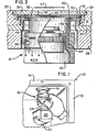
- a frame member 10 is provided with a side portion 12 and a top portion 14, the top portion having an opening 16 therein for receiving a lens carrying structure or assembly 18 shown in position to be installed in an apertured support structure for subsequent operation.
- a lens cube 20 is supported from a cradle 22 and is provided with a protective cover 24.
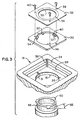
- FIG. 3 An enlarged view of the several parts of the lens mount shown in the exploded view of Figure 3 includes the top portion 14 of a reference plate 25 and the aperture 16 in a plate portion 26.
- the plate portion 26, also seen in Figure 2 is formed adjacent a base plate 27 and the reference member 25 to provide a recess 28 for receipt of a female bayonet plate 30 and a one-piece, planar, spring element 32.
- Tapped holes 36 are provided in the bayonet plate 30 and also apertures 38 in the clamping spring 32 for receipt of screws 40 to secure the spring 32 to the bayonet plate 30.
- the plate 30 is positioned in abutting manner with the central portion 34 of the reference plate 25.
- a pin 31 is provided in the plate 25 on opposite sides of the aperture 16 to match a hole and a slot in the plate 30.
- a cover plate 33 with an opening 35 therein is secured by screws 37 in tapped holes 39 of the reference plate 25.
- the lens assembly 18 comprises a lens holder 42 ( Figure 2) adapted to enclose and retain a particular lens of a stated magnification (42x) and has threads 44 on a peripheral portion thereof for engaging with threads 46 on an interior diameter of a male set bayonet 48.
- the male bayonet 48 is provided with screw means 49 or the like for tightening adjacent portions thereof so as to precisely position and retain the lens holder 42 in relation to the bayonet 48. In this manner, the lens is set for proper focus relative to a microimage plane 47 above the lens assembly 18 and, when the critical focus is established and set, the focus condition will remain until the lens is removed from the holder 42.
- the male bayonet 48 has three lugs or tabs 50 (Figure 3) at the upper end thereof, equally spaced and extending outwardly to engage with the female bayonet plate 30 and against the clamping spring 32.
- the bayonet plate 30 is seated in the recess 28 of the stepped portion of reference plate 25 and, with the spring 32 secured to the plate 30 and retained by the cover plate 33, the lugs or tabs 50 are held in place by the respective planar surfaces of the several parts.
- the cover plate 33 has four gaskets or pads 51 to provide clearance for the screws 40 and also to enable adjustment at the several corners of the plate 33.
- the diameter of the aperture 16 in the plate portion 26 and the diameter of the aperture 52 in the bayonet plate 30 enable the male bayonet 48 with its lugs 50 to pass through the apertures with the apertures having clearance diameters.
- the plate 30 includes lugs or tabs 54 and the spring 32 includes a central aperture 55 having a diameter approximately the diameter of the internal threaded portion of the male bayonet 48 so as to provide a seat for the lugs or tabs 50 of the male bayonet 48 within the gap between the plate lugs 54 and an interior portion 56 adjacent the aperture 55 of the spring 32, and defined by the offset 57 of the lugs 54 from the upper surface of the plate 30.
- Each of the male bayonet lugs 50 has an inclined or slanted surface of fifteen degrees, as shown by the arrow 58, on the underside at one edge of each lug so as to enable ease of engagement in the gap between the lugs 54 and the portion 56 of spring 32 when the lens assembly 18 is being installed by turning in a clockwise direction as seen in Figure 1.
- One of the lugs 54 of the plate 30 has a stop pin 60 for limiting the extent of travel of the male bayonet 48.
- the lugs or tabs 50 have a beveled entry angle of fifteen degrees and have a thickness of 2.41 millimeters for fitting in a gap of 2.16 millimeters provided between the lugs 54 of the female bayonet plate 30 and the resilient portion 56 of the spring 32.
- the male bayonet 48 is turned to engage the tabs or lugs 50 thereof with the lugs 54 of female bayonet plate 30
- the interference fit of 0.25 millimeters requires the portion 56 of spring 32 to push or bias the lugs 50 of the lens carrying structure 18 downwards against the lugs 54 of the bayonet plate 30.
- the spring 32 is calculated to provide a minimum of 4.5 kilograms of clamping force with the 0.25 millimeters interference fit.
- the resilient portion 56 adjacent the aperture 55 of the spring 32 is of at least sufficient distance from the aperture to cover the lugs 54 in overlapping manner.
- the resilient portion 56 extends at least from the aperture 55, which may be approximately the diameter of the interior edge of the lugs 54, to an imaginary circle, as shown by the phantom line on the clamping member 32 of Figure 3, the imaginary circle being approximately the diameter 52 of the plate member 30. It is, of course, feasible and may be preferred that the clamping member be made entirely of resilient material of the same composition.
- the bayonet-mounted lens holder is a precision device in that controlled spring pressure maintains the lens assembly against a reference surface for repeatable positioning of the lens assembly in precise manner.
- controlled spring pressure maintains the lens assembly against a reference surface for repeatable positioning of the lens assembly in precise manner.
- the lens assembly 18 is positioned within the apparatus utilizing such lens assembly, as seen in Figure 1, and upon moving the lugs 50 of the bayonet 48 up into the plane of the gap 57 between the lugs 54 of the bayonet plate 30 and the resilient portion 56 of the clamping spring 32, the lens assembly 18 is rotated by hand about 35 degrees to engage the respective lugs and to seat one lug 50 against the stop pin 60 and thereby precisely position the lens in relation to the plane 47.
- the clamping spring 32 biases or urges the bayonet 48 in a downwardly direction to firmly press the lugs 50 against the lugs 54 of the plate 30.
- lugs 50 may be a part of a portion attached to an apertured support member and the member 30 may be a part of the bayonet 48 and cooperable with the clamping spring 32.
- a plate member and a planar spring having cooperating portions thereon similar to lugs 54 of member 30 and the resilient portion 56 of spring 32 could be secured to the lens carrying member and the support member could carry lugs similar to lugs 50 for the purpose of precisely positioning the lens carrying member.
- the support member could have the lugs downwardly positioned and extending outwardly in a plane perpendicular from the axis of the aperture in the support member and when the lens assembly with the plate member and the planar spring attached thereto are positioned to receive the lugs of the support member, the spring would bias or urge the lugs of the support member in the space between the resilient portion of the spring and the lugs of the plate member. It should be noted that both the spring and the plate member would require access portions on the interior diameters to allow passage of the outwardly extending lugs of the support member and then include inwardly extending tabs, similar to tabs 54 shown in Figure 3, to provide the seat therebetween for the lugs of the support member.
- a further modification of the clamping or resilient member may include a larger internal diameter than is shown in Figure 3 and having a plurality of resilient portions angularly corresponding with the lugs 54 of the bayonet plate 30 to thereby enable passage of the member 48 with lugs 50 through the apertures and to place the lugs 50 between the resilient portions of the clamping member and the lugs 54.
- the lugs 50 may require a beveled portion on each end thereof to properly engage in the space between the portions of the clamping spring and the tabs of the bayonet plate member.
- the resilient portions may be separated only by a kerf provided to form a plurality of resilient portions at least in sufficient diametral distance to cover the lugs of the member 50 and the tabs of the plate member 30.
Landscapes
- Physics & Mathematics (AREA)
- General Physics & Mathematics (AREA)
- Optics & Photonics (AREA)
- Lens Barrels (AREA)
- Structure And Mechanism Of Cameras (AREA)
Applications Claiming Priority (2)
| Application Number | Priority Date | Filing Date | Title |
|---|---|---|---|
| US06/029,506 US4281895A (en) | 1979-04-12 | 1979-04-12 | Quick change lens mount |
| US29506 | 1979-04-12 |
Publications (3)
| Publication Number | Publication Date |
|---|---|
| EP0026222A1 EP0026222A1 (en) | 1981-04-08 |
| EP0026222A4 EP0026222A4 (en) | 1981-08-31 |
| EP0026222B1 true EP0026222B1 (en) | 1983-07-27 |
Family
ID=21849386
Family Applications (1)
| Application Number | Title | Priority Date | Filing Date |
|---|---|---|---|
| EP80900849A Expired EP0026222B1 (en) | 1979-04-12 | 1980-10-23 | Bayonet type lens mounting |
Country Status (7)
| Country | Link |
|---|---|
| US (1) | US4281895A (ja) |
| EP (1) | EP0026222B1 (ja) |
| JP (1) | JPS56500395A (ja) |
| BE (1) | BE882748A (ja) |
| CA (1) | CA1143198A (ja) |
| DE (1) | DE3064362D1 (ja) |
| WO (1) | WO1980002202A1 (ja) |
Families Citing this family (38)
| Publication number | Priority date | Publication date | Assignee | Title |
|---|---|---|---|---|
| FR2512760B1 (fr) * | 1981-09-16 | 1987-03-20 | Dba | Unite de commande de freinage a assemblage rapide |
| US4564270A (en) * | 1983-07-05 | 1986-01-14 | Surgikos, Inc. | Objective lens cover for an operating microscope |
| US4532672A (en) * | 1984-05-23 | 1985-08-06 | Enamel Products & Plating Co | Doorstop having bayonet engageable bracket and separately mounted shield |
| US4551110A (en) * | 1984-05-24 | 1985-11-05 | Cpg Products Corp. | Rotatable cam for use in a toy construction set |
| IT1179694B (it) * | 1984-05-29 | 1987-09-16 | Agusta Aeronaut Costr | Assieme motore trasmissione per elicottero |
| DE3579324D1 (de) * | 1984-10-17 | 1990-09-27 | Sekisui Chemical Co Ltd | Kugelventil. |
| FR2588116B1 (fr) * | 1985-10-01 | 1988-01-08 | Framatome Sa | Dispositif de verrouillage d'une bague de guidage sur une plaque comportant une ouverture et son application a un tube guide de reacteur nucleaire |
| JPH01259309A (ja) * | 1988-04-08 | 1989-10-17 | Minolta Camera Co Ltd | 半導体レーザとコリメータレンズとの軸出し及びフォーカス調整機構 |
| US4877432A (en) * | 1988-06-17 | 1989-10-31 | The Scott Fetzer Company | Disposable dust bag for vacuum cleaners and the like |
| US5064455A (en) * | 1988-06-17 | 1991-11-12 | The Scott Fetzer Company | Disposable dust bag for vacuum cleaners and the like |
| US5014923A (en) * | 1990-04-09 | 1991-05-14 | Eastman Kodak Company | Web-spool for a cartridge |
| US5530547A (en) * | 1994-08-04 | 1996-06-25 | Arnold; Steven M. | Method and apparatus for aligning optical elements and testing aspheric optical components |
| US5772355A (en) * | 1996-12-19 | 1998-06-30 | Precision Optics Corporation | Quick attach/release adapter mechanism |
| US7379112B1 (en) * | 1999-08-31 | 2008-05-27 | Honeywell Silent Witness Inc. | Quick change lens mount |
| US6359740B1 (en) * | 2000-09-20 | 2002-03-19 | San Hua Tien Precision Circuit Co., Ltd. | Image capturing device |
| US6900913B2 (en) * | 2001-01-23 | 2005-05-31 | Wen-Ching Chen | Image pickup module |
| US6942255B2 (en) * | 2002-04-23 | 2005-09-13 | Q3Jmc, Inc. | Twist fitting for air tank connections |
| US20050041421A1 (en) * | 2003-08-21 | 2005-02-24 | Gary Lamolinara | Light fixture assembly |
| US7154567B2 (en) * | 2004-02-09 | 2006-12-26 | Genius Electronic Optical Co., Ltd. | Projection lens regulator for rear projection television |
| JP2005275027A (ja) * | 2004-03-25 | 2005-10-06 | Fujinon Corp | レンズマウント構造 |
| US8259401B2 (en) * | 2004-11-19 | 2012-09-04 | Eastman Kodak Company | Castellated optical mounting structure |
| US7474482B2 (en) * | 2005-04-19 | 2009-01-06 | Intermec Ip Corp. | Optical data reader with removable lens system |
| TWI322229B (en) * | 2005-05-13 | 2010-03-21 | Delta Electronics Inc | Fixing assembly for vehicle heat-dissipating fan and use method thereof |
| CN1869456B (zh) * | 2005-05-26 | 2012-09-05 | 台达电子工业股份有限公司 | 固定汽车散热风扇组件及方法 |
| CN1873233B (zh) * | 2005-05-31 | 2011-05-11 | 台达电子工业股份有限公司 | 汽车散热风扇扇框及其固定组件 |
| US7527299B1 (en) * | 2005-12-06 | 2009-05-05 | William Shawn Collier | Container discharge and fill port fitting |
| DE102006022049B4 (de) * | 2006-05-09 | 2013-01-31 | Esw Gmbh | Anschlusseinrichtung für Wechselobjektive |
| CN101470241B (zh) * | 2007-12-27 | 2011-08-24 | 鸿富锦精密工业(深圳)有限公司 | 镜片安装座 |
| US20130215253A1 (en) * | 2012-02-16 | 2013-08-22 | Pawel Achtel | Underwater lens mount system for underwater motion picture cameras |
| CN103217770B (zh) * | 2013-04-18 | 2015-06-10 | 苏州佳世达光电有限公司 | 镜头固定模组及使用其的投影装置 |
| CN203702759U (zh) * | 2014-01-20 | 2014-07-09 | 思博特有限公司 | 一种轻便的旋转自锁式快拆锁扣装置 |
| CN107076957B (zh) * | 2014-09-26 | 2019-06-25 | 浜松光子学株式会社 | 固体浸没透镜保持器及图像取得装置 |
| EP3470916B1 (en) * | 2016-06-10 | 2022-01-05 | Fujitsu Frontech Limited | Imaging device |
| JP6666440B2 (ja) * | 2016-06-15 | 2020-03-13 | 富士通フロンテック株式会社 | 撮像装置 |
| CN106199897B (zh) * | 2016-07-07 | 2019-04-26 | 苏州佳世达光电有限公司 | 镜头固定模组以及投影装置 |
| GB2553788A (en) * | 2016-09-14 | 2018-03-21 | Eaton Ind Netherlands Bv | Sight glass |
| DE102018130629B3 (de) | 2018-12-03 | 2020-04-23 | Carl Mahr Holding Gmbh | Objektivhalterung und Verbindungseinrichtung für das auswechselbare Anbringen eines Objektivs |
| CN109764213B (zh) * | 2019-02-15 | 2024-03-26 | 中山大山摄影器材有限公司 | 用于摄像器材的可拆卸地快速连接装置和摄像器材组件 |
Family Cites Families (9)
| Publication number | Priority date | Publication date | Assignee | Title |
|---|---|---|---|---|
| US757712A (en) * | 1903-05-05 | 1904-04-19 | Jacob F Arnold | Table-leg attachment. |
| GB488665A (en) * | 1936-02-04 | 1938-07-12 | Kodak Ltd | Improvements in or relating to means for detachably supporting an objective mount onphotographic cameras and other apparatus |
| US2461357A (en) * | 1944-12-06 | 1949-02-08 | Broido Jacques Jean | Camera objective mounting |
| US2496928A (en) * | 1947-12-06 | 1950-02-07 | Eastman Kodak Co | Bayonet lock |
| US2652828A (en) * | 1951-03-26 | 1953-09-22 | Willson Products Inc | Respirator |
| FR1147684A (fr) * | 1955-04-16 | 1957-11-28 | Optische Werke Steinheil Gmbh | Objectif photographique, en particulier à grande distance focale |
| US3429606A (en) * | 1967-07-13 | 1969-02-25 | Roger N Brasseur | Container lifting device |
| FR2276494A1 (fr) * | 1974-06-26 | 1976-01-23 | Citroen Sa | Dispositif destine a etre fixe rapidement sur une paroi, notamment pour servir de passage a un cable |
| JPS54160148U (ja) * | 1978-04-28 | 1979-11-08 |
-
1979
- 1979-04-12 US US06/029,506 patent/US4281895A/en not_active Expired - Lifetime
-
1980
- 1980-03-18 CA CA000347872A patent/CA1143198A/en not_active Expired
- 1980-03-31 DE DE8080900849T patent/DE3064362D1/de not_active Expired
- 1980-03-31 WO PCT/US1980/000339 patent/WO1980002202A1/en active IP Right Grant
- 1980-03-31 JP JP50102880A patent/JPS56500395A/ja active Pending
- 1980-04-11 BE BE0/200192A patent/BE882748A/fr not_active IP Right Cessation
- 1980-10-23 EP EP80900849A patent/EP0026222B1/en not_active Expired
Also Published As
| Publication number | Publication date |
|---|---|
| DE3064362D1 (en) | 1983-09-01 |
| JPS56500395A (ja) | 1981-03-26 |
| EP0026222A1 (en) | 1981-04-08 |
| CA1143198A (en) | 1983-03-22 |
| WO1980002202A1 (en) | 1980-10-16 |
| EP0026222A4 (en) | 1981-08-31 |
| US4281895A (en) | 1981-08-04 |
| BE882748A (fr) | 1980-07-31 |
Similar Documents
| Publication | Publication Date | Title |
|---|---|---|
| EP0026222B1 (en) | Bayonet type lens mounting | |
| US5249082A (en) | Exact constraint arrangement for and methods of mounting an element such as a lens | |
| US4496217A (en) | Actuating device for photographic lens assembly | |
| US5210644A (en) | Cam mechanism of lens | |
| US5644441A (en) | Lens mount for TV camera | |
| US5678953A (en) | Connecting mechanism | |
| US4266855A (en) | Quick change lens system | |
| US3696725A (en) | Adjustable camera-objective | |
| US4668047A (en) | Lens holding system | |
| GB2125879A (en) | Mounting of interchangeable accessories on lighting units | |
| US6369960B2 (en) | Securing device for light interception frame | |
| US5555051A (en) | Back-focus adjusting device for a video camera | |
| EP1162490B1 (en) | Lens fixture | |
| US5052788A (en) | Microscope | |
| EP0580936A1 (en) | Diffraction element and optical pick-up assembly | |
| US2936685A (en) | Camera wall and optical mount construction | |
| EP0583287A1 (en) | CARRIER FOR OPTICAL ELEMENTS. | |
| US5246192A (en) | Mounting apparatus for a scanner camera | |
| US4020496A (en) | Support for components of an automatic focusing system | |
| US4319836A (en) | Optical device of a copying apparatus | |
| US6337775B1 (en) | Collet lens mount | |
| US4591239A (en) | Optical lens holder | |
| US6222671B1 (en) | Optical element switching device | |
| JPH1152210A (ja) | 光学素子保持装置およびこれを備えた光学機器 | |
| JP3699758B2 (ja) | ターレットおよび位置調整機構および顕微鏡 |
Legal Events
| Date | Code | Title | Description |
|---|---|---|---|
| PUAI | Public reference made under article 153(3) epc to a published international application that has entered the european phase |
Free format text: ORIGINAL CODE: 0009012 |
|
| AK | Designated contracting states |
Designated state(s): DE FR GB |
|
| 17P | Request for examination filed |
Effective date: 19810309 |
|
| DET | De: translation of patent claims | ||
| GRAA | (expected) grant |
Free format text: ORIGINAL CODE: 0009210 |
|
| AK | Designated contracting states |
Designated state(s): DE FR GB |
|
| REF | Corresponds to: |
Ref document number: 3064362 Country of ref document: DE Date of ref document: 19830901 |
|
| ET | Fr: translation filed | ||
| PLBE | No opposition filed within time limit |
Free format text: ORIGINAL CODE: 0009261 |
|
| STAA | Information on the status of an ep patent application or granted ep patent |
Free format text: STATUS: NO OPPOSITION FILED WITHIN TIME LIMIT |
|
| 26N | No opposition filed | ||
| PGFP | Annual fee paid to national office [announced via postgrant information from national office to epo] |
Ref country code: FR Payment date: 19890126 Year of fee payment: 10 |
|
| PGFP | Annual fee paid to national office [announced via postgrant information from national office to epo] |
Ref country code: GB Payment date: 19890131 Year of fee payment: 10 |
|
| PGFP | Annual fee paid to national office [announced via postgrant information from national office to epo] |
Ref country code: DE Payment date: 19890403 Year of fee payment: 10 |
|
| PG25 | Lapsed in a contracting state [announced via postgrant information from national office to epo] |
Ref country code: GB Effective date: 19900331 |
|
| REG | Reference to a national code |
Ref country code: FR Ref legal event code: TP |
|
| GBPC | Gb: european patent ceased through non-payment of renewal fee | ||
| PG25 | Lapsed in a contracting state [announced via postgrant information from national office to epo] |
Ref country code: FR Effective date: 19901130 |
|
| PG25 | Lapsed in a contracting state [announced via postgrant information from national office to epo] |
Ref country code: DE Effective date: 19901201 |
|
| REG | Reference to a national code |
Ref country code: FR Ref legal event code: ST |