EP0025756B1 - Circuit de réglage de la température d'un four de cuisson, notamment à usage domestique - Google Patents
Circuit de réglage de la température d'un four de cuisson, notamment à usage domestique Download PDFInfo
- Publication number
- EP0025756B1 EP0025756B1 EP19800401280 EP80401280A EP0025756B1 EP 0025756 B1 EP0025756 B1 EP 0025756B1 EP 19800401280 EP19800401280 EP 19800401280 EP 80401280 A EP80401280 A EP 80401280A EP 0025756 B1 EP0025756 B1 EP 0025756B1
- Authority
- EP
- European Patent Office
- Prior art keywords
- temperature
- oven
- resistance
- acceleration
- sensor
- Prior art date
- Legal status (The legal status is an assumption and is not a legal conclusion. Google has not performed a legal analysis and makes no representation as to the accuracy of the status listed.)
- Expired
Links
- 238000010411 cooking Methods 0.000 title claims description 7
- 238000010438 heat treatment Methods 0.000 claims description 22
- 230000001133 acceleration Effects 0.000 claims description 15
- 229910052751 metal Inorganic materials 0.000 claims description 10
- 239000002184 metal Substances 0.000 claims description 10
- BASFCYQUMIYNBI-UHFFFAOYSA-N platinum Chemical compound [Pt] BASFCYQUMIYNBI-UHFFFAOYSA-N 0.000 claims description 8
- 230000033228 biological regulation Effects 0.000 claims description 6
- 230000000694 effects Effects 0.000 claims description 6
- PXHVJJICTQNCMI-UHFFFAOYSA-N Nickel Chemical compound [Ni] PXHVJJICTQNCMI-UHFFFAOYSA-N 0.000 claims description 4
- 229910052697 platinum Inorganic materials 0.000 claims description 4
- 230000001105 regulatory effect Effects 0.000 claims description 3
- 229910001030 Iron–nickel alloy Inorganic materials 0.000 claims description 2
- 229910052782 aluminium Inorganic materials 0.000 claims description 2
- XAGFODPZIPBFFR-UHFFFAOYSA-N aluminium Chemical compound [Al] XAGFODPZIPBFFR-UHFFFAOYSA-N 0.000 claims description 2
- 229910052759 nickel Inorganic materials 0.000 claims description 2
- 230000001944 accentuation Effects 0.000 claims 1
- 239000004411 aluminium Substances 0.000 claims 1
- 230000007423 decrease Effects 0.000 description 7
- 239000000523 sample Substances 0.000 description 5
- 239000000463 material Substances 0.000 description 4
- 238000010586 diagram Methods 0.000 description 3
- 230000010355 oscillation Effects 0.000 description 3
- 238000005530 etching Methods 0.000 description 2
- 230000002411 adverse Effects 0.000 description 1
- 239000004020 conductor Substances 0.000 description 1
- 238000007796 conventional method Methods 0.000 description 1
- 238000009434 installation Methods 0.000 description 1
- 238000004519 manufacturing process Methods 0.000 description 1
- 238000005259 measurement Methods 0.000 description 1
Images

Classifications
-
- F—MECHANICAL ENGINEERING; LIGHTING; HEATING; WEAPONS; BLASTING
- F24—HEATING; RANGES; VENTILATING
- F24C—DOMESTIC STOVES OR RANGES ; DETAILS OF DOMESTIC STOVES OR RANGES, OF GENERAL APPLICATION
- F24C7/00—Stoves or ranges heated by electric energy
- F24C7/08—Arrangement or mounting of control or safety devices
- F24C7/087—Arrangement or mounting of control or safety devices of electric circuits regulating heat
-
- G—PHYSICS
- G05—CONTROLLING; REGULATING
- G05D—SYSTEMS FOR CONTROLLING OR REGULATING NON-ELECTRIC VARIABLES
- G05D23/00—Control of temperature
- G05D23/19—Control of temperature characterised by the use of electric means
- G05D23/30—Automatic controllers with an auxiliary heating device affecting the sensing element, e.g. for anticipating change of temperature
Definitions
- the present invention relates to electric cooking ovens, in particular for domestic use and, more particularly, a circuit for adjusting the temperature of such ovens.
- heating element close to the temperature sensor which is switched on at the same time as the elements ensuring the heating of the enclosure served by the regulatory system.
- This heating element which is most often a small electrical resistance, accelerates the influence that the sensor has on the adjustment loop or, in other words, it reduces the difference between the maximum and minimum temperatures prevailing in the 'enclosure and therefore maintains the instantaneous temperature as close as possible to the set temperature.
- the object of the invention is to provide an adjustment circuit which makes it possible, while comprising only one temperature sensor, to reduce the oscillations of the temperature around the set value throughout the range of use of a baking oven regardless of the number of heating elements used therein.
- control circuit for a cooking oven, in particular for domestic use which is heated by at least one heating element controlled as a function of temperature by a loop.
- control which includes a single sensor to provide the instantaneous value of the temperature prevailing in the oven and heating means placed near the sensor to accelerate the effect on the regulation, this circuit being so structured that said heating means are arranged in such a way that the heat they give off decreases as the temperature of the oven increases.
- the heating means associated with the sensor are formed by an electrical resistance called acceleration whose temperature coefficient ensures the decrease in the amount of heat released with the increase in temperature.
- Said electrical acceleration resistance is supplied by a constant voltage source and the material from which it is made has a resistance with a positive temperature coefficient.
- the resistance is made of a metal whose temperature range is compatible with that of the oven, such as platinum.
- the temperature sensor and the acceleration resistance are both made of a resistance metal with a positive temperature coefficient, the two components being provided on the same support plate by etching a layer of this metal applied to said wafer.
- This particular characteristic of the invention makes it possible to achieve a considerable saving during the production of the adjustment loop, because, the temperature probe being conveniently carried out conventionally on a wafer by etching a layer of metal, it is very easy, without increasing the cost price, to engrave next to the probe a second component forming said acceleration resistor.
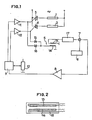
- FIG. 1 The simplified diagram of FIG. 1 shows two heating elements 1 and 2 placed respectively in the roof and the bottom of a cooking oven, for domestic use in particular. Each element is mounted in series with a triac 3, 4 on a supply network such as the sector for example.
- the heating elements 1 and 2 are controlled by an adjustment loop 5 which firstly comprises a display member 6 of the temperature set point.
- This display member 6 is connected to a comparator 7, the output of which is connected, by means of an amplifier 8 to a bistable rocker 9.
- the latter is intended to ensure the distribution of the heat released by the elements 1 and 2 in the oven enclosure by a selective and alternating start of these elements.
- the duty cycle of the bistable rocker 9 can be adjusted using a control member 10, in order to adapt the heating regime to the dishes to be cooked.
- the two outputs of the rocker 9 are applied respectively to amplifiers 11 and 12 which in turn drive the control electrodes of the triacs 3 and 4.
- the signal corresponding to the instantaneous value of the oven temperature is detected by a resistor 13 forming a temperature sensor, which is preferably made of a metal having a resistor with a positive temperature coefficient, compatible with the range of temperatures which may occur. in the oven.
- the sensor 13 is placed in the immediate vicinity of heating means which in this example are formed by another resistor 14 in order to accelerate the effect of the sensor 13 on the regulation of the loop 5.
- the resistor 14 is supplied with constant voltage by means of diodes 15 and 16 which are connected respectively to the outputs of the amplifiers 11 and 12.
- the sensor 13 supplies a signal to a measurement circuit 17 which drives the second input of the comparator 7.
- the “acceleration" resistor 14 is made of a conductive material having a resistance whose temperature coefficient ensures the decrease in the amount of heat it gives off, as the temperature of the oven increases; in the case shown, this coefficient is positive.
- the resistance is preferably made of platinum, like the sensor 13, although other materials can be envisaged, such as for example nickel, aluminum, an iron-nickel alloy and in general any compatible material. with the range of temperatures prevailing in the oven. Those skilled in the art will immediately see that to the extent that the acceleration resistance is supplied with constant current it must have a negative temperature coefficient.
- the probe 13 and the resistor 14 are made of the same metal such as platinum, it is advantageous to use, as shown in FIG. 2, an insulating plate 18 on which they are etched for example by laser, from a layer of this metal previously deposited on the plate. This can then be placed on a wall of the oven enclosure. As an indication, the values of the probe 13 and of the resistor 14 can both be equal to 100 ohms.
- Fig. 3 illustrates the operation of the regulation circuit according to the invention.
- the curve shows the shape of the temperature within the oven, the line drawn in fine lines corresponding to the use of a conventional adjustment loop while we have shown in bold lines how the temperature changes with a resistance d connected acceleration according to the invention.
- the temperature quickly reaches the displayed value which is 100 ° C., for example.
- the adjustment loop 5 causes the temperature to oscillate around this value with a given amplitude which, when a simple resistance to sensor 13 is associated as in the conventional technique, it is reduced to a certain value (5% for example). It can be seen that, still with such a conventional resistance, this amplitude is no longer as great when the user at times t, or t 2 displays other oven temperatures (200 ° C and 300 ° C for example) because the amplitude decreases as the oven temperature increases.
- particular acceleration resistor of the invention makes it possible to modulate its influence on the sensor 13 so that the amplitude for the lower ranges is practically as low as for the upper ranges, since the power dissipated by the resistor 14 decreases with the temperature in its action on the probe 13 ultimately leads to decrease its influence as the temperature increases.
- the heating means associated with the sensor impose on the latter a variation in the heating which is caused by the temperature coefficient of the resistive material of which they are made.
Landscapes
- Engineering & Computer Science (AREA)
- Chemical & Material Sciences (AREA)
- Combustion & Propulsion (AREA)
- Mechanical Engineering (AREA)
- General Engineering & Computer Science (AREA)
- Physics & Mathematics (AREA)
- General Physics & Mathematics (AREA)
- Automation & Control Theory (AREA)
- Electric Stoves And Ranges (AREA)
- Control Of Temperature (AREA)
Applications Claiming Priority (2)
| Application Number | Priority Date | Filing Date | Title |
|---|---|---|---|
| FR7922548 | 1979-09-10 | ||
| FR7922548A FR2465177A1 (fr) | 1979-09-10 | 1979-09-10 | Circuit de reglage de la temperature d'un four de cuisson, notamment a usage domestique |
Publications (2)
| Publication Number | Publication Date |
|---|---|
| EP0025756A1 EP0025756A1 (fr) | 1981-03-25 |
| EP0025756B1 true EP0025756B1 (fr) | 1985-02-06 |
Family
ID=9229503
Family Applications (1)
| Application Number | Title | Priority Date | Filing Date |
|---|---|---|---|
| EP19800401280 Expired EP0025756B1 (fr) | 1979-09-10 | 1980-09-08 | Circuit de réglage de la température d'un four de cuisson, notamment à usage domestique |
Country Status (3)
| Country | Link |
|---|---|
| EP (1) | EP0025756B1 (enExample) |
| DE (1) | DE3070112D1 (enExample) |
| FR (1) | FR2465177A1 (enExample) |
Families Citing this family (1)
| Publication number | Priority date | Publication date | Assignee | Title |
|---|---|---|---|---|
| FR2555391B1 (fr) * | 1983-11-18 | 1986-04-18 | Airelec Ind | Dispositif electronique de compensation de derive pour thermostat |
Family Cites Families (5)
| Publication number | Priority date | Publication date | Assignee | Title |
|---|---|---|---|---|
| NL76054C (enExample) * | 1900-01-01 | |||
| DE2014397A1 (de) * | 1969-04-01 | 1970-10-08 | Texas Instruments Inc | Überwachungseinrichtung für ein Kühlmittel |
| US3605875A (en) * | 1969-09-04 | 1971-09-20 | Texas Instruments Inc | Electrothermal time proportioning temperature control |
| DE2212157A1 (de) * | 1972-03-14 | 1973-09-20 | Ego Elektro Blanc & Fischer | Regler fuer elektrokochplatten |
| US3979708A (en) * | 1974-11-04 | 1976-09-07 | General Electric Company | Thermostat and anticipator therefor |
-
1979
- 1979-09-10 FR FR7922548A patent/FR2465177A1/fr active Granted
-
1980
- 1980-09-08 EP EP19800401280 patent/EP0025756B1/fr not_active Expired
- 1980-09-08 DE DE8080401280T patent/DE3070112D1/de not_active Expired
Also Published As
| Publication number | Publication date |
|---|---|
| EP0025756A1 (fr) | 1981-03-25 |
| FR2465177B1 (enExample) | 1982-11-12 |
| FR2465177A1 (fr) | 1981-03-20 |
| DE3070112D1 (en) | 1985-03-21 |
Similar Documents
| Publication | Publication Date | Title |
|---|---|---|
| EP0607313B1 (fr) | Sole chauffante destinee a assurer le chauffage d'un objet dispose a sa surface et reacteur de traitement chimique muni de ladite sole | |
| FR2706645A1 (fr) | Procédé de régulation de la température d'un système. | |
| FR2728132A1 (fr) | Dispositif de chauffage par induction de recipient et procede de commande d'un tel dispositif | |
| FR2760931A1 (fr) | Ensemble capteur-dispositif de chauffage | |
| EP0284115A1 (fr) | Dispositif de contrôle de la charge de batteries rechargeables | |
| EP0606440B1 (fr) | Procede de grillage et/ou de rechauffage d'un produit agroalimentaire, et dispositif de mise en oeuvre dudit procede | |
| EP0025756B1 (fr) | Circuit de réglage de la température d'un four de cuisson, notamment à usage domestique | |
| FR2511152A1 (fr) | Procede d'utilisation d'un vacuometre de pirani regle et vacuometre de pirani approprie | |
| BE510498A (fr) | Systeme de reglage de grandeurs physiques | |
| EP1850446A1 (fr) | Procédé de charge de batterie avec compensation de resistance interne, chargeur et batterie pour la mise en oeuvre de ce procédé | |
| FR2728071A1 (fr) | Debitmetre massique a fil chaud | |
| FR2587828A1 (fr) | Appareil et procede permettant d'obtenir une stabilite des rapports resistifs amelioree dans un reseau diviseur resistif | |
| EP0082768A2 (fr) | Capteur de température et dispositif l'incorporant | |
| FR2793104A1 (fr) | Procede de pilotage d'un element chauffant d'appareil electrique de chauffage de liquide | |
| FR2649555A1 (fr) | Procede et dispositif de commande de l'alimentation de charges, adaptes pour reduire les fluctuations de tension sur le reseau | |
| EP0746181A1 (fr) | Procédé de décongélation automatique d'un aliment placé dans un four à micro-ondes | |
| EP0555455B1 (fr) | Procede de mesure de la temperature de la zone de sertissage ou de soudage lors d'une operation de sertissage a chaud ou de soudage par points, et procedes de controle de parametres d'operation de sertissage et de soudage par points | |
| FR3060127A1 (fr) | Procede de compensation dynamique de l'erreur d'offset d'une chaine d'acquisition comportant un capteur de courant | |
| FR2706610A1 (fr) | Capteur de flux thermique et dispositif de mesure associé. | |
| EP3890432A1 (fr) | Plaque de cuisson comprenant un programme de cuisson amélioré, système de cuisson, procédé de cuisson et programme correspondant | |
| EP0105770A1 (fr) | Enceinte de chauffage électrique industriel | |
| FR2749067A1 (fr) | Electronique de regulation avec un corps de chauffage a rayonnement | |
| FR2583947A1 (fr) | Dispositif de branchement pour la commande de puissance de chauffage dans des cuisinieres electriques | |
| EP2200397B1 (fr) | Procédé d'alimentation en puissance d'au moins un élément électrique et appareil de cuisson mettant en oeuvre le procédé | |
| EP1199621B1 (fr) | Procédé de régulation de la température dans un four de cuisson électrique |
Legal Events
| Date | Code | Title | Description |
|---|---|---|---|
| PUAI | Public reference made under article 153(3) epc to a published international application that has entered the european phase |
Free format text: ORIGINAL CODE: 0009012 |
|
| AK | Designated contracting states |
Designated state(s): BE DE GB IT NL |
|
| 17P | Request for examination filed |
Effective date: 19810508 |
|
| ITF | It: translation for a ep patent filed | ||
| GRAA | (expected) grant |
Free format text: ORIGINAL CODE: 0009210 |
|
| AK | Designated contracting states |
Designated state(s): BE DE GB IT NL |
|
| REF | Corresponds to: |
Ref document number: 3070112 Country of ref document: DE Date of ref document: 19850321 |
|
| PGFP | Annual fee paid to national office [announced via postgrant information from national office to epo] |
Ref country code: NL Payment date: 19850930 Year of fee payment: 6 |
|
| PLBE | No opposition filed within time limit |
Free format text: ORIGINAL CODE: 0009261 |
|
| STAA | Information on the status of an ep patent application or granted ep patent |
Free format text: STATUS: NO OPPOSITION FILED WITHIN TIME LIMIT |
|
| 26N | No opposition filed | ||
| PG25 | Lapsed in a contracting state [announced via postgrant information from national office to epo] |
Ref country code: BE Effective date: 19860930 |
|
| BERE | Be: lapsed |
Owner name: DE DIETRICH & CIE Effective date: 19860930 |
|
| PG25 | Lapsed in a contracting state [announced via postgrant information from national office to epo] |
Ref country code: NL Effective date: 19870401 |
|
| NLV4 | Nl: lapsed or anulled due to non-payment of the annual fee | ||
| GBPC | Gb: european patent ceased through non-payment of renewal fee | ||
| PG25 | Lapsed in a contracting state [announced via postgrant information from national office to epo] |
Ref country code: GB Effective date: 19881118 |
|
| PG25 | Lapsed in a contracting state [announced via postgrant information from national office to epo] |
Ref country code: DE Effective date: 19890601 |