EP0025423A1 - Taphole opening apparatus for blast furnaces - Google Patents
Taphole opening apparatus for blast furnaces Download PDFInfo
- Publication number
- EP0025423A1 EP0025423A1 EP80850129A EP80850129A EP0025423A1 EP 0025423 A1 EP0025423 A1 EP 0025423A1 EP 80850129 A EP80850129 A EP 80850129A EP 80850129 A EP80850129 A EP 80850129A EP 0025423 A1 EP0025423 A1 EP 0025423A1
- Authority
- EP
- European Patent Office
- Prior art keywords
- guide rail
- latch
- socket
- carriage
- impact sleeve
- Prior art date
- Legal status (The legal status is an assumption and is not a legal conclusion. Google has not performed a legal analysis and makes no representation as to the accuracy of the status listed.)
- Granted
Links
- 229910000831 Steel Inorganic materials 0.000 claims abstract description 16
- 239000010959 steel Substances 0.000 claims abstract description 16
- 238000005553 drilling Methods 0.000 claims abstract description 10
- 230000008878 coupling Effects 0.000 claims description 5
- 238000010168 coupling process Methods 0.000 claims description 5
- 238000005859 coupling reaction Methods 0.000 claims description 5
- 230000035515 penetration Effects 0.000 claims 2
- 238000000605 extraction Methods 0.000 abstract description 5
- 231100001261 hazardous Toxicity 0.000 abstract description 2
- 238000010079 rubber tapping Methods 0.000 description 8
- XEEYBQQBJWHFJM-UHFFFAOYSA-N Iron Chemical compound [Fe] XEEYBQQBJWHFJM-UHFFFAOYSA-N 0.000 description 6
- 239000002184 metal Substances 0.000 description 4
- 229910052751 metal Inorganic materials 0.000 description 4
- 229910052742 iron Inorganic materials 0.000 description 3
- 238000000034 method Methods 0.000 description 3
- 230000000149 penetrating effect Effects 0.000 description 2
- 241001062472 Stokellia anisodon Species 0.000 description 1
- 229910000746 Structural steel Inorganic materials 0.000 description 1
- QVGXLLKOCUKJST-UHFFFAOYSA-N atomic oxygen Chemical compound [O] QVGXLLKOCUKJST-UHFFFAOYSA-N 0.000 description 1
- 230000006835 compression Effects 0.000 description 1
- 238000007906 compression Methods 0.000 description 1
- 238000010276 construction Methods 0.000 description 1
- 238000013016 damping Methods 0.000 description 1
- 238000003780 insertion Methods 0.000 description 1
- 230000037431 insertion Effects 0.000 description 1
- 235000000396 iron Nutrition 0.000 description 1
- 229910052760 oxygen Inorganic materials 0.000 description 1
- 239000001301 oxygen Substances 0.000 description 1
- 230000000717 retained effect Effects 0.000 description 1
Images


Classifications
-
- C—CHEMISTRY; METALLURGY
- C21—METALLURGY OF IRON
- C21B—MANUFACTURE OF IRON OR STEEL
- C21B7/00—Blast furnaces
- C21B7/12—Opening or sealing the tap holes
Definitions
- taphole opening for the smelt from blast furnaces or other metallurgical ovens was performed according to the classical method of drilling through the plugging mass by a percussive and rotary drilling machine.
- a drill steel is actuated by a hammer drill to drill an initial part of the hole and the hole is subsequently completed by an oxygen lance or by the use of a consumable poking bar manually to crush through the remaining plugging so as to open hole for the molten metal.
- the taphole can be drilled in one single operation by means of an expendable tubular drill steel tool driven by a hammer drill through the plugging into the molten metal for opening up as described for example in the French patent 2093292.
- a different technique is now beginning to be utilized. It consists of drilling immediately after plugging a hole of a length of about two thirds of the thickness of the blast furnace wall into the still fresh plugging mass directly after such drilling piercing through by force the remaining third of the fresh mass by a steel bar until it reaches the molten iron and acts as a closing plug in the plugging mass for the metal while extending outwardly through the mass into the runner trench.
- the steel bar is left in such plugging position and presents at its free extremity suitable coupling means.
- a device able to produce a rapid extraction is then coupled to and withdraws said bar so as to de-plug or to open the taphole and to permit the molten iron to run out into the runner trench.
- the plugging bar is regarded being consumable and is hereinafter therefore called lost bar.
- the main object of the invention is to present for the aforementioned recently introduced different technique a more economic and more safe taphole opening apparatus adaptable to existant tapping machines and in particular relying on impact sleeve means of an improved construction.
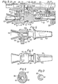
- Fig 1 is a diagrammatic side view of the taphole opening apparatus according to the invention in position for drilling an initial hole into a blast furnace wall.
- Fig 2 is a bottom view in the direction of arrow 17 in Fig 1 and indicates diagrammatically the supporting standard forming part of the apparatus.
- Fig 3 is an enlarged view on the line 3-3 in Fig 1.
- Fig 4 is an enlarged side view of the hammer drill in Fig 1 mounted for extracting a lost bar.
- Fig 5 is a partial section on an enlarged scale showing the extractor carriage and impact sleeve of Fig 4 in position for extracting a lost bar.
- Fig 6 is a view of the impact sleeve in Fig 5 in a position for driving the lost bar forwardly.
- Fig 7 is a partly sectional top view of the impact sleeve in Fig. 5.
- Fig 8 is a sectional view on line 8-8 in Fig 5.
- Fig 9 is a sectional view on line 9-9 in Fig 5.
- Fig 10 is a section on line 10-10 in Fig 5.
- Fig 11 is a bottom view of an impact yoke shown in Fig 10.
- Fig 12 is a side view of the impact yoke in Fig 11.
- Fig 13 is a fragmentary view on an enlarged scale of a centralizer forming part of the apparatus.
- a taphole opening apparatus incorporating the invention is shown in working position adjacent the wall of a blast furnace 20 into the freshly applied plugging mass 21 of which there is first to be drilled an initial tapping hole and then driven a plugging bar or lost bar 53 all through the mass as a continuation of the initial hole.
- a carriage 28 can be displaced to and fro under the action of a feed motor 24 and a feed chain 26 laid over spockets 25.
- the carriage 28 is suspended movably on and along opposed flanges 23 on the guide rail 22 by a number of pairs of opposed rollers 27.
- the carriage 28, Figs 4 and 5 is preferably divided into a front portion, the extractor carriage 29 and a rear portion, the drill carriage 28 proper, the latter carrying a conventional preferably compressed air driven hammer drill 30 having the usual built-in drill rotation means, not shown.
- the feed chain 26 is, via a shackle 33 and a drive bolt 32 (Fig 5) received therein, in driving connection with the extractor carriage 29 which in its turn is connected to the drill carriage 28 by side bolts 34 (Fig 4) fixed to a lug 35 formed on the drill carriage 28 and passing through an ear 36 on the extractor carriage 29 interposed between a pair of vibration damping Belleville-spring packages 37 under suitable compression.
- the guide rail 22 is mounted on a standard 38 and a transverse arm 41 so as to be turnable as indicated by arrow 14, Fig 2, about a vertical axis 39 between a turned away position of rest, not shown, and the working position indicated in Figs 1 and 2 and back again, and tilted by arm 41 about a horizontal axis 40 as indicated by arrow 15 in Fig 1 between a horizontal position of rest and the inclined working position shown in Fig 1.
- a centralizer 42 for either a drill steel 43 having a bit 44 thereon or for the lost bar 53,Fig 4, 5.
- the lost bar 53 has a reduced diameter shank portion 86 thereon providing a ' rear shoulder 87.
- a bracket 45 is affixed to the guide rail opposite'to the centralizer 42 and carries spurs 46 for engagement with the wall of the blast furnace 20 while a power cylinder, not shown, may be provided for moving the guide rail 22 longitudinally relative to the standard 38 to attain such engagement.
- Hammer drill 30 has the usual forwardly protruding shank adaptor 47 to which may be threaded an extension sleeve 48, Fig 1, in its turn in threaded connection with the drill steel 43.
- the shank adaptor 47 can alternatively transmit the impacts it receives from the hammer drill 30 to an impact sleeve 50, Figs 4, 5, which in Fig 1 has been removed from the extractor carriage 29 to make room for the extension sleeve 48.
- the impact sleeve 50 Fig 5-7, is provided with two longitudinal axially aligned bores, one of them, socket or bore 51 for receiving the shank of the lost bar 53 and the other, bore 52 for receiving the shank adaptor 47.
- Socket 51 has an impact transmitting bottom surface 63 and widens conically in outward direction defining a funnel 54 on impact sleeve 50, while bore 52 is open laterally to the exterior of sleeve 50, Fig 7, so as to allow sidewise introduction of the shank adaptor 47 when impact sleeve 50 is to be mounted on extractor carriage 29.
- Bore 52 also defines an anvil surface 55 at its bottom.
- a cross opening 56 receiving slidably a latch 57 therein extends into socket 51, Fig 8.
- a stop screw 58 on sleeve 50 cooperates with a groove 59 on latch 57 to prevent it from falling out of the cross opening 56 (Fig 6) and to allow it to project into socket 51 (Fig 5).
- An inclination 60 allows the latch 57 to be pushed aside from such projected position as a result of introduction of the shank of a lost bar 53 into socket 51 to the position indicated in Fig 5.
- a downwardly pointing u-shaped leaf spring 61 suspended in brackets 49 on extractor carriage 29 and the weight of latch 57 urges said latch 57 into socket 51 in the position shown in Fig 5,again in the position of Fig 6 the weight thereof urges latch 57 out from socket 51.
- the impact sleeve 50 has a waist 62 of reduced diameter having opposed flattened sides 64.
- An impact yoke 68 is received between the members 66 and straddles each terminal lug 66 by pairs of laterally directed projection 69.
- Outwardly and on each member 66 is affixed an L-shaped angle iron 71 each having a bore 72 adjacent its lower member. These bores 72 are coaxial and in alignment with corresponding bores 73 in the impact yoke 68.
- a retaining pin 74 may be stuck through the bores 72, 73 thereby locking the impact yoke 68 to the U-bracket 65 and thus to the extractor carriage 29.
- the yoke 68 is intended for straddling the waist 62 of impact sleeve 50 before insertion of the retaining pin 74, which then selectively extends along either one of the flattened sides 64 of the waist 62 and thereby locks the impact sleeve 50 to the carriage in either one of two positions.
- the centralizer 42 is provided with a downwardly pointing guide opening 76 of rounded V-shape adjacent to which are affixed two parallel axles 77, 78 about which are pivotable respectively a guide lever 79 and a latch lever 80.
- the guide lever 79 has a guide opening 81 at the outer end thereof and can either occupy an expelling or catching position illustrated by dash and dot lines in Fig 13 at the mouth of guide opening 76, or a guiding position shown by full lines and being in alignment with and closing downwardly guide opening 76.
- Latch lever 80 in this latter position by reason of its weight bias engages the outer end 82 of the guide lever 79 by a lug 83 thereby latching and keeping the guide lever 79 in guiding position.
- a shackle 88 is affixed to latch lever 80 and is connected to an actuating rod 84 or cable, not shown in detail, that is guided in suitable way along guide rail 22 and standard 38 so as to be remotely actuated from the operator-s stand or panel 85 in safe position with respect to the taphole at 21 and the runner trench thereunder, not shown.
- guide rail 22 is then turned about vertical axis 39 of standard 38 to the angular position of arm 41-in Fig 2 and then inclined by being tilted about axis 40 until the apparatus occupies the position shown in Fig 1.
- the initial hole to a depth of about two thirds of the thickness of the mud plug 21 can now be drilled under remote control from stand 85.
- the retaining pin 74 is then driven in place into bores 72, 73, Fig 10, thereby locking impact sleeve 50 and impact yoke 68 to bracket 65 and thus to the extractor carriage 29.
- the lost bar 53 is then put in place manually by its shank portion being inserted via the funnel 54 into socket 51 of impact sleeve 50. Simultaneously therewith the outer end of lost bar 53 is lifted up into the guide opening 81 of guide lever 79 on the centralizer 42, which lever 79 first occupies the position represented by dash and dot lines in Fig 13. The lifting is continued until lost bar 53 is received centrally in the main guide opening 76 at which instant guide lever 79 will be latched by latch lever 80 in the position depicted by full lines in Fig 13.
- guide rail 22 is then turned about vertical axis 39 of standard 38 so as to face the wall of blast furnace 20 and is then again tilted somewhat downwardly about horizontal axis 40 so as to bring lost bar 53 into alignment with the just pre-drilled initial hole in mud plug 21.
- Hammer drill 30 can now be remotely actuated and displaced by movement of and together with the extractor carriage 29 along guide rail 22 driving and piercing by percussive action lost bar 53 through the remaining bottom of the initial hole in the mud plug 21 until penetrating into the molten metal in the interior of blast furnace 20.
- shank adaptor 47 rotating due to the built-in rotation of the hammer drill 30, is allowed to rotate freely in bore 52 while pounding the anvil surface 55 therein.
- Lost bar 53 is then released from centralizer 42 by remote actuation from stand 85 of latch lever 80, more particularly by drawing the rod 84 (or the actuation cable) connected to shackle 88. Thereafter guide rail 22 is first tilted upwards and then brought back to the position of rest. Lost bar 53 is left to remain in the tapping hole while closing it and keeping it closed in the manner of a valve plug.
- shank adapter 47 is removed from the hammer drill 30 together with drill steel 43 and a suitably dimensioned extension sleeve 48 and another similar shank adapter 47 is then alone inserted into hammer drill 30 before impact sleeve 50 is mounted into yoke 68 and locked thereto by retaining pin 74.
- the described positioning machinery incorporating standard 38 can obviously be replaced by other equivalent conventional positioning means, for example guide rail hoists or mobile posi- tioners displaceable from one metallurgical oven to another and having adjacent each of them a safe position of rest sufficiently distant from the working position so as to practically avoid accidents.
- other equivalent conventional positioning means for example guide rail hoists or mobile posi- tioners displaceable from one metallurgical oven to another and having adjacent each of them a safe position of rest sufficiently distant from the working position so as to practically avoid accidents.
Landscapes
- Engineering & Computer Science (AREA)
- Chemical & Material Sciences (AREA)
- Manufacturing & Machinery (AREA)
- Materials Engineering (AREA)
- Metallurgy (AREA)
- Organic Chemistry (AREA)
- Earth Drilling (AREA)
- Blast Furnaces (AREA)
- Central Heating Systems (AREA)
- Cleaning In General (AREA)
- Cleaning By Liquid Or Steam (AREA)
- Crystals, And After-Treatments Of Crystals (AREA)
Abstract
Description
- Up to now taphole opening for the smelt from blast furnaces or other metallurgical ovens was performed according to the classical method of drilling through the plugging mass by a percussive and rotary drilling machine. According to one prior alternative a drill steel is actuated by a hammer drill to drill an initial part of the hole and the hole is subsequently completed by an oxygen lance or by the use of a consumable poking bar manually to crush through the remaining plugging so as to open hole for the molten metal. According to another prior alternative the taphole can be drilled in one single operation by means of an expendable tubular drill steel tool driven by a hammer drill through the plugging into the molten metal for opening up as described for example in the French patent 2093292.
- A different technique is now beginning to be utilized. It consists of drilling immediately after plugging a hole of a length of about two thirds of the thickness of the blast furnace wall into the still fresh plugging mass directly after such drilling piercing through by force the remaining third of the fresh mass by a steel bar until it reaches the molten iron and acts as a closing plug in the plugging mass for the metal while extending outwardly through the mass into the runner trench. The steel bar is left in such plugging position and presents at its free extremity suitable coupling means. Later at the tapping instant a device able to produce a rapid extraction is then coupled to and withdraws said bar so as to de-plug or to open the taphole and to permit the molten iron to run out into the runner trench. The plugging bar is regarded being consumable and is hereinafter therefore called lost bar.
- There are machines on the market which permit realization of this succession of steps but necessitate in the first place the use of special bidirectionally percussive hammer drills with a separate rotation motor that can be shut off. These machines are thus able to produce impact action to the rear in the extracting sense without rotary movement, and demand manual intervention for coupling the lost bar left in the hole to the extraction device fixed on the tapping apparatus which preferably may be brought into a retracted position of rest for leaving free the runner for repair purposes after a preceding tapping. The use of double impact and separate rotation hammer drills obviously is cumbersome and expensive, while manual coupling near the taphole runner trench is hazardous for the operator. Furthermore, two operators are necessary for these operations, one at the control stand of the machine and the other in the vicinity of the tapping hole.
- As a consequence, the main object of the invention is to present for the aforementioned recently introduced different technique a more economic and more safe taphole opening apparatus adaptable to existant tapping machines and in particular relying on impact sleeve means of an improved construction.
- In the appended drawings Fig 1 is a diagrammatic side view of the taphole opening apparatus according to the invention in position for drilling an initial hole into a blast furnace wall.
- Fig 2 is a bottom view in the direction of
arrow 17 in Fig 1 and indicates diagrammatically the supporting standard forming part of the apparatus. - Fig 3 is an enlarged view on the line 3-3 in Fig 1.
- Fig 4 is an enlarged side view of the hammer drill in Fig 1 mounted for extracting a lost bar.
- Fig 5 is a partial section on an enlarged scale showing the extractor carriage and impact sleeve of Fig 4 in position for extracting a lost bar.
- Fig 6 is a view of the impact sleeve in Fig 5 in a position for driving the lost bar forwardly.
- Fig 7 is a partly sectional top view of the impact sleeve in Fig. 5.
- Fig 8 is a sectional view on line 8-8 in Fig 5.
- Fig 9 is a sectional view on line 9-9 in Fig 5.
- Fig 10 is a section on line 10-10 in Fig 5.
- Fig 11 is a bottom view of an impact yoke shown in Fig 10.
- Fig 12 is a side view of the impact yoke in Fig 11.
- Fig 13 is a fragmentary view on an enlarged scale of a centralizer forming part of the apparatus.
- In Figures 1 and 2 a taphole opening apparatus incorporating the invention is shown in working position adjacent the wall of a
blast furnace 20 into the freshly applied pluggingmass 21 of which there is first to be drilled an initial tapping hole and then driven a plugging bar or lostbar 53 all through the mass as a continuation of the initial hole. Along a guide rail 22 acarriage 28 can be displaced to and fro under the action of afeed motor 24 and afeed chain 26 laid overspockets 25. As shown in Figs 3 and 4 thecarriage 28 is suspended movably on and alongopposed flanges 23 on theguide rail 22 by a number of pairs ofopposed rollers 27. Thecarriage 28, Figs 4 and 5, is preferably divided into a front portion, theextractor carriage 29 and a rear portion, thedrill carriage 28 proper, the latter carrying a conventional preferably compressed air drivenhammer drill 30 having the usual built-in drill rotation means, not shown. Thefeed chain 26 is, via a shackle 33 and a drive bolt 32 (Fig 5) received therein, in driving connection with theextractor carriage 29 which in its turn is connected to thedrill carriage 28 by side bolts 34 (Fig 4) fixed to a lug 35 formed on thedrill carriage 28 and passing through anear 36 on theextractor carriage 29 interposed between a pair of vibration damping Belleville-spring packages 37 under suitable compression. - The
guide rail 22 is mounted on a standard 38 and atransverse arm 41 so as to be turnable as indicated byarrow 14, Fig 2, about avertical axis 39 between a turned away position of rest, not shown, and the working position indicated in Figs 1 and 2 and back again, and tilted byarm 41 about ahorizontal axis 40 as indicated by arrow 15 in Fig 1 between a horizontal position of rest and the inclined working position shown in Fig 1. At the forward end of theguide rail 22 there is mounted acentralizer 42 for either adrill steel 43 having a bit 44 thereon or for the lostbar 53,Fig 4, 5. The lostbar 53 has a reduceddiameter shank portion 86 thereon providing a'rear shoulder 87. - A
bracket 45 is affixed to the guide rail opposite'to thecentralizer 42 and carries spurs 46 for engagement with the wall of theblast furnace 20 while a power cylinder, not shown, may be provided for moving theguide rail 22 longitudinally relative to the standard 38 to attain such engagement.Hammer drill 30 has the usual forwardly protrudingshank adaptor 47 to which may be threaded an extension sleeve 48, Fig 1, in its turn in threaded connection with thedrill steel 43. Theshank adaptor 47 can alternatively transmit the impacts it receives from thehammer drill 30 to animpact sleeve 50, Figs 4, 5, which in Fig 1 has been removed from theextractor carriage 29 to make room for the extension sleeve 48. - The
impact sleeve 50, Fig 5-7, is provided with two longitudinal axially aligned bores, one of them, socket or bore 51 for receiving the shank of the lostbar 53 and the other, bore 52 for receiving theshank adaptor 47.Socket 51 has an impact transmittingbottom surface 63 and widens conically in outward direction defining afunnel 54 onimpact sleeve 50, whilebore 52 is open laterally to the exterior ofsleeve 50, Fig 7, so as to allow sidewise introduction of theshank adaptor 47 whenimpact sleeve 50 is to be mounted onextractor carriage 29.Bore 52 also defines ananvil surface 55 at its bottom. Across opening 56 receiving slidably alatch 57 therein extends intosocket 51, Fig 8. Astop screw 58 onsleeve 50 cooperates with agroove 59 onlatch 57 to prevent it from falling out of the cross opening 56 (Fig 6) and to allow it to project into socket 51 (Fig 5). Aninclination 60 allows thelatch 57 to be pushed aside from such projected position as a result of introduction of the shank of a lostbar 53 intosocket 51 to the position indicated in Fig 5. A downwardly pointing u-shaped leaf spring 61 suspended inbrackets 49 onextractor carriage 29 and the weight oflatch 57 urges saidlatch 57 intosocket 51 in the position shown in Fig 5,again in the position of Fig 6 the weight thereof urgeslatch 57 out fromsocket 51. Theimpact sleeve 50 has awaist 62 of reduced diameter having opposed flattened sides 64. - The
extractor carriage 29, through which thedrive bolt 32 is threaded, carries a u-shaped downwardly directedbracket 65 theside members 66 of which are terminated by rectangular downwardly poiting lugs 67. Animpact yoke 68 is received between themembers 66 and straddles eachterminal lug 66 by pairs of laterally directedprojection 69. Outwardly and on eachmember 66 is affixed an L-shapedangle iron 71 each having abore 72 adjacent its lower member. These bores 72 are coaxial and in alignment withcorresponding bores 73 in theimpact yoke 68. A retainingpin 74 may be stuck through thebores impact yoke 68 to the U-bracket 65 and thus to theextractor carriage 29. Theyoke 68 is intended for straddling thewaist 62 ofimpact sleeve 50 before insertion of the retainingpin 74, which then selectively extends along either one of the flattenedsides 64 of thewaist 62 and thereby locks theimpact sleeve 50 to the carriage in either one of two positions. - The
centralizer 42, Fig 13, is provided with a downwardly pointing guide opening 76 of rounded V-shape adjacent to which are affixed twoparallel axles guide lever 79 and alatch lever 80. Theguide lever 79 has aguide opening 81 at the outer end thereof and can either occupy an expelling or catching position illustrated by dash and dot lines in Fig 13 at the mouth ofguide opening 76, or a guiding position shown by full lines and being in alignment with and closing downwardly guideopening 76.Latch lever 80 in this latter position by reason of its weight bias engages theouter end 82 of theguide lever 79 by alug 83 thereby latching and keeping theguide lever 79 in guiding position. Ashackle 88 is affixed to latchlever 80 and is connected to an actuating rod 84 or cable, not shown in detail, that is guided in suitable way alongguide rail 22 and standard 38 so as to be remotely actuated from the operator-s stand orpanel 85 in safe position with respect to the taphole at 21 and the runner trench thereunder, not shown. - Let it be assumed that the
guide rail 22 and the elements supported thereby occupy a safe position turned away or retracted from the blast furnace, for example angularly off-set by 90 to 180 degrees with respect to the position shown in Fig 2. Immediately after plugging the taphole at 21 in the wall of theblast furnace 20 it is necessary to drill an initial hole of certain length into the still freshtaphole plugging mass 21. - To this end and in
case impact sleeve 50 still remains affixed in place inextractor carriage 29 after the preceding operation of extracting and removing a lost bar,impact sleeve 50 andyoke 68 are removed and put aside after removal of retainingpin 74. By a conventional threaded extension sleeve 48-thedrill steel 43 carrying bit 44 is connected toshank adaptor 47 and set in rotation and impacted byhammer drill 30. As depicted in Fig 1 the extension sleeve 48 will now occupy a position belowextractor carriage 29 and freely spaced betweenmembers 66 and lugs 67 of U-bracket 65 thereof. By conventional hydraulic remote control fromstand 85guide rail 22 is then turned aboutvertical axis 39 of standard 38 to the angular position of arm 41-in Fig 2 and then inclined by being tilted aboutaxis 40 until the apparatus occupies the position shown in Fig 1. The initial hole to a depth of about two thirds of the thickness of themud plug 21 can now be drilled under remote control fromstand 85. - After initial drilling,
guide rail 22 byarm 41 is returned to a safe angularly off-set position of rest and the extension sleeve 48 is manually disconnected from theshank adaptor 47 together with thedrill steel 43 and bit 44. By a vertical upward movement theimpact sleeve 50 together with the straddlingimpact yoke 68 thereon are then positioned in place manually intobracket 65 ofextractor carriage 29 with thebore 52 ofimpact sleeve 50 in a position opposite to Fig 7 as to be able to receive theshank adaptor 47 ofhammer drill 30. Theimpact sleeve 50 is then manually turned to a position corresponding to Fig 6 in which theplug 57 leaves thesocket 51 by gravitation but is retained by thestop screw 58. The retainingpin 74 is then driven in place intobores impact sleeve 50 andimpact yoke 68 tobracket 65 and thus to theextractor carriage 29. The lostbar 53 is then put in place manually by its shank portion being inserted via thefunnel 54 intosocket 51 ofimpact sleeve 50. Simultaneously therewith the outer end of lostbar 53 is lifted up into the guide opening 81 ofguide lever 79 on thecentralizer 42, whichlever 79 first occupies the position represented by dash and dot lines in Fig 13. The lifting is continued until lostbar 53 is received centrally in the main guide opening 76 at whichinstant guide lever 79 will be latched bylatch lever 80 in the position depicted by full lines in Fig 13. - By remote control from
stand 85 guide rail 22 is then turned aboutvertical axis 39 of standard 38 so as to face the wall ofblast furnace 20 and is then again tilted somewhat downwardly abouthorizontal axis 40 so as to bring lostbar 53 into alignment with the just pre-drilled initial hole inmud plug 21.Hammer drill 30 can now be remotely actuated and displaced by movement of and together with theextractor carriage 29 alongguide rail 22 driving and piercing by percussive action lostbar 53 through the remaining bottom of the initial hole in themud plug 21 until penetrating into the molten metal in the interior ofblast furnace 20. During such driving theshank adaptor 47, rotating due to the built-in rotation of thehammer drill 30, is allowed to rotate freely inbore 52 while pounding theanvil surface 55 therein. -
Lost bar 53 is then released fromcentralizer 42 by remote actuation fromstand 85 oflatch lever 80, more particularly by drawing the rod 84 (or the actuation cable) connected to shackle 88. Thereafter guiderail 22 is first tilted upwards and then brought back to the position of rest.Lost bar 53 is left to remain in the tapping hole while closing it and keeping it closed in the manner of a valve plug. - Later, when it becomes time to extract lost
bar 53 for opening the taphole,impact sleeve 50 after removal of retainingpin 74 is first turned 180 degrees in theyoke 68 andbracket 65 until it occupies the position depicted in Fig 5 and retainingpin 74 is then reinserted as shown.Guide rail 22 is then again turned and tilted to its working position by remote control fromstand 85. Tilting about thehorizontal axis 40 results in the lostbar 53 penetrating into the centralizer guide openings8l, 76 and being latched in such position bylatch lever 80. By remote actuation fromstand 85 of thefeed motor 24extractor carriage 29 is then advanced towards theblast furnace 20 until the shank of lostbar 53 is caught byfunnel 54 and directed intosocket 51 past theinclination 60 oflatch 57 againstbottom surface 63 ofsocket 51.Latch 57 is hereunder lifted aside intocross opening 56 and then falls back under the combined action of its weight and the bias of leaf spring 61 thus locking lostbar 53 at itsrear shoulder 87 at the instant when the reduceddiameter shank portion 86 aligns withlatch 57. By remote actuation offeed motor 24extractor carriage 29 is moved backwards alongguide rail 22 whilehammer drill 30pounds shank adapter 47,impact sleeve 50 at itsanvil surface 55 inbore 52, and the shank of lostbar 57 at impact transmittingbottom surface 63 ofimpact sleeve 50. As a result lostbar 53 is per- cussively extracted thereby opening the taphole for the flow of molten iron. Upon theguide rail 22 having been turned and tilted back to its position ofrest centralizer 42 can be remotely actuated to release lostbar 53.Impact sleeve 50 can then be disassembled manually for purposes of preparing the taphole opening apparatus for the next identically performed taphole drilling, taphole plugging and subsequent taphole opening cycle. - In the above described manual handling of
drill steel 43,impact sleeve 50, andyoke 68, the operator may in some cases prefer to letyoke 68, Figs. 5, and 10-12, remain permanently affixed to U-bracket 65, andcarriage 29, in which case he will gain some operational time and have to manipulate solely impactsleeve 50. This is attained simply by using somewhat broadened lower members ofangle irons 71, Fig. 10, as locking supports for and below theopposed projections 69 onyoke 68 wherebyyoke 68 will remain in place even when retainingpin 74 is removed. During disassembly ofdrill steel 43 in this case preferablyshank adapter 47 is removed from thehammer drill 30 together withdrill steel 43 and a suitably dimensioned extension sleeve 48 and anothersimilar shank adapter 47 is then alone inserted intohammer drill 30 beforeimpact sleeve 50 is mounted intoyoke 68 and locked thereto by retainingpin 74. - As evident from the foregoing all manual operations on the apparatus are effected in its position of rest by one operator safely outside the running trench and remote from the tapping hole.
- The described positioning machinery incorporating standard 38 can obviously be replaced by other equivalent conventional positioning means, for example guide rail hoists or mobile posi- tioners displaceable from one metallurgical oven to another and having adjacent each of them a safe position of rest sufficiently distant from the working position so as to practically avoid accidents.
Claims (6)
Priority Applications (1)
| Application Number | Priority Date | Filing Date | Title |
|---|---|---|---|
| AT80850129T ATE5900T1 (en) | 1979-09-05 | 1980-09-04 | TAPHOLE DRILLING DEVICE FOR BLAST FURNACES. |
Applications Claiming Priority (2)
| Application Number | Priority Date | Filing Date | Title |
|---|---|---|---|
| FR7922167A FR2464303A1 (en) | 1979-09-05 | 1979-09-05 | DEVICE FOR PUSHING IN AND REMOVING, BY PERCUSSION USING A SINGLE HAMMER AND WITH AUTOMATIC LOCKING, A BAR, FOR EXAMPLE A BAR IN CONTACT WITH THE CAST IRON AND PROJECTING OUTSIDE A BLAST FURNACE |
| FR7922167 | 1979-09-05 |
Publications (2)
| Publication Number | Publication Date |
|---|---|
| EP0025423A1 true EP0025423A1 (en) | 1981-03-18 |
| EP0025423B1 EP0025423B1 (en) | 1984-01-18 |
Family
ID=9229366
Family Applications (1)
| Application Number | Title | Priority Date | Filing Date |
|---|---|---|---|
| EP80850129A Expired EP0025423B1 (en) | 1979-09-05 | 1980-09-04 | Taphole opening apparatus for blast furnaces |
Country Status (9)
| Country | Link |
|---|---|
| US (1) | US4378054A (en) |
| EP (1) | EP0025423B1 (en) |
| AT (1) | ATE5900T1 (en) |
| BR (1) | BR8005641A (en) |
| CA (1) | CA1144365A (en) |
| DE (1) | DE3066185D1 (en) |
| ES (1) | ES8104830A1 (en) |
| FR (1) | FR2464303A1 (en) |
| SU (1) | SU1011057A3 (en) |
Cited By (11)
| Publication number | Priority date | Publication date | Assignee | Title |
|---|---|---|---|---|
| EP0041942A1 (en) * | 1980-06-06 | 1981-12-16 | Vereinigte Edelstahlwerke Aktiengesellschaft (Vew) | Method of alternately closing and opening the tap hole of metallurgical furnaces, especially of blast furnaces |
| FR2502175A1 (en) * | 1981-03-21 | 1982-09-24 | Dango & Dienenthal Maschbau | PUNCHING MACHINE |
| EP0064645A1 (en) * | 1981-05-05 | 1982-11-17 | Paul Wurth S.A. | Guiding and positioning mechanism for the drill hammer of the taphole in a shaft furnace, and drilling device provided with this mechanism |
| EP0064644A1 (en) * | 1981-05-05 | 1982-11-17 | Paul Wurth S.A. | Guiding and positioning mechanism for the drill hammer of the taphole in a shaft furnace, and drilling device provided with this mechanism |
| FR2545103A1 (en) * | 1983-04-28 | 1984-11-02 | Wurth Paul Sa | Blast furnace tapping rod manipulation |
| EP0128432A2 (en) * | 1983-06-08 | 1984-12-19 | Paul Wurth S.A. | Tap hole drilling machine for shaft furnaces |
| US4669707A (en) * | 1985-11-01 | 1987-06-02 | Lakeway Manufacturing, Inc. | Apparatus and process for tapping molten metal furnaces using a rotary percussion mill |
| FR2619036A1 (en) * | 1987-08-04 | 1989-02-10 | Wurth Paul Sa | DRILLING MACHINE FOR A TANK HOLE OVEN |
| FR2621264A1 (en) * | 1987-10-06 | 1989-04-07 | Wurth Paul Sa | DEVICE FOR MOUNTING A CLAMP FOR COUPLING A DRILLING ROD OF THE CASING HOLE OF A TANK OVEN TO A DRILLING MACHINE |
| EP0552476A2 (en) * | 1992-01-24 | 1993-07-28 | Paul Wurth S.A. | Apparatus for opening the taphole of a shaft furnace |
| EP0573766A1 (en) * | 1992-06-10 | 1993-12-15 | Paul Wurth S.A. | Combination clamping chuck for a shaft furnace taphole piercing machine |
Families Citing this family (5)
| Publication number | Priority date | Publication date | Assignee | Title |
|---|---|---|---|---|
| NO301134B1 (en) * | 1995-08-25 | 1997-09-15 | Knut O Dalland | Multi-joint work boom for a work machine |
| AT407919B (en) * | 1998-01-19 | 2001-07-25 | Boehler Pneumatik Internat Gmb | PNEUMATICALLY OR HYDRAULICALLY OPERATING HAMMER AND USE OF THE HAMMER TO OPEN OR SEAL A TAP OPENING OF A METALLURGICAL VESSEL |
| US6299830B2 (en) | 1998-09-22 | 2001-10-09 | Meltran, Inc. | Apparatus and method for tapping a furnace |
| US6663825B2 (en) | 1999-07-19 | 2003-12-16 | Louis A. Grant, Inc. | Method and apparatus for installing or replacing a furnace tap hole insert |
| AT511616B1 (en) | 2011-09-08 | 2013-01-15 | Tmt Bbg Res And Dev Gmbh | DEVICE FOR SUPPLYING DISHWASHER IN A DRILLING HAMMER |
Citations (7)
| Publication number | Priority date | Publication date | Assignee | Title |
|---|---|---|---|---|
| FR1083328A (en) * | 1953-01-30 | 1955-01-07 | Ingersoll Rand Canada | Hole punch connector |
| US2789789A (en) * | 1953-07-03 | 1957-04-23 | Jr Luke Lea | Rock drills |
| FR1308811A (en) * | 1961-10-28 | 1962-11-09 | Westinghouse Air Brake Co | Blast furnace installation and casting method |
| US3121769A (en) * | 1964-02-18 | Apparatus for opening the tap hole of a metallurgical furnace | ||
| US3516651A (en) * | 1967-10-16 | 1970-06-23 | Toyo Kogyo Co | Rail mounted drilling machine for furnace tap hole |
| FR2093292A5 (en) * | 1970-06-09 | 1972-01-28 | Atlas Copco France | Furnace tapping tool - for molten metal |
| US3862750A (en) * | 1972-10-17 | 1975-01-28 | Inland Steel Co | Tophole opening apparatus |
Family Cites Families (13)
| Publication number | Priority date | Publication date | Assignee | Title |
|---|---|---|---|---|
| US273443A (en) * | 1883-03-06 | Vania | ||
| US911755A (en) * | 1908-12-04 | 1909-02-09 | Cyclone Drill Company | Hand-power drill. |
| US1055594A (en) * | 1912-07-31 | 1913-03-11 | Robert Fleming Arnott | Power-operated hammer. |
| US1595064A (en) * | 1922-04-10 | 1926-08-10 | Bulkrug Machine Corp | Power-transmitting mechanism |
| US1977645A (en) * | 1931-09-22 | 1934-10-23 | Edmund W Roberts | Gasoline hammer |
| US2035156A (en) * | 1935-03-18 | 1936-03-24 | Edmond Marti | Drill puller |
| DE704014C (en) * | 1938-10-19 | 1941-03-21 | Fried Krupp Akt Ges | Holding device for the drill bit of rock drilling machines, consisting of two arms rotatable about parallel axes |
| FR863775A (en) * | 1939-09-29 | 1941-04-09 | Cie Ingersoll Rand | Improvements to automatic feeders for hammer drills |
| US2293443A (en) * | 1940-02-20 | 1942-08-18 | Mossberg & Sons O F | Portable power driven hammer |
| FR1234072A (en) * | 1959-04-21 | 1960-10-14 | Dango & Dienenthal K G | Device for opening the tap hole of metallurgical furnaces, shaft furnaces and blast furnaces in particular |
| US3845826A (en) * | 1973-02-23 | 1974-11-05 | Skil Corp | Rotary disconnect for a rotary hammer tool |
| DE2339395A1 (en) * | 1973-08-03 | 1975-02-13 | Richard Lemcke | Attachment for percussive drills - riveting etc function by cancelling torque to apply impact only to tool |
| DE2509805B2 (en) * | 1975-03-06 | 1976-12-23 | Dango & Dienenthai, 5900 Siegen | TUBE HOLE DRILLING OR PLUGGING MACHINE FOR SHAFT, IN PARTICULAR BIG FURNACE |
-
1979
- 1979-09-05 FR FR7922167A patent/FR2464303A1/en active Granted
-
1980
- 1980-09-03 ES ES494721A patent/ES8104830A1/en not_active Expired
- 1980-09-03 US US06/183,804 patent/US4378054A/en not_active Expired - Lifetime
- 1980-09-04 BR BR8005641A patent/BR8005641A/en unknown
- 1980-09-04 EP EP80850129A patent/EP0025423B1/en not_active Expired
- 1980-09-04 AT AT80850129T patent/ATE5900T1/en not_active IP Right Cessation
- 1980-09-04 DE DE8080850129T patent/DE3066185D1/en not_active Expired
- 1980-09-04 CA CA000359744A patent/CA1144365A/en not_active Expired
- 1980-09-04 SU SU802977959A patent/SU1011057A3/en active
Patent Citations (7)
| Publication number | Priority date | Publication date | Assignee | Title |
|---|---|---|---|---|
| US3121769A (en) * | 1964-02-18 | Apparatus for opening the tap hole of a metallurgical furnace | ||
| FR1083328A (en) * | 1953-01-30 | 1955-01-07 | Ingersoll Rand Canada | Hole punch connector |
| US2789789A (en) * | 1953-07-03 | 1957-04-23 | Jr Luke Lea | Rock drills |
| FR1308811A (en) * | 1961-10-28 | 1962-11-09 | Westinghouse Air Brake Co | Blast furnace installation and casting method |
| US3516651A (en) * | 1967-10-16 | 1970-06-23 | Toyo Kogyo Co | Rail mounted drilling machine for furnace tap hole |
| FR2093292A5 (en) * | 1970-06-09 | 1972-01-28 | Atlas Copco France | Furnace tapping tool - for molten metal |
| US3862750A (en) * | 1972-10-17 | 1975-01-28 | Inland Steel Co | Tophole opening apparatus |
Cited By (20)
| Publication number | Priority date | Publication date | Assignee | Title |
|---|---|---|---|---|
| EP0041942A1 (en) * | 1980-06-06 | 1981-12-16 | Vereinigte Edelstahlwerke Aktiengesellschaft (Vew) | Method of alternately closing and opening the tap hole of metallurgical furnaces, especially of blast furnaces |
| FR2502175A1 (en) * | 1981-03-21 | 1982-09-24 | Dango & Dienenthal Maschbau | PUNCHING MACHINE |
| DE3111260A1 (en) * | 1981-03-21 | 1982-09-30 | Dango & Dienenthal Maschinenbau GmbH, 5900 Siegen | STITCH HOLE DRILL |
| EP0064645A1 (en) * | 1981-05-05 | 1982-11-17 | Paul Wurth S.A. | Guiding and positioning mechanism for the drill hammer of the taphole in a shaft furnace, and drilling device provided with this mechanism |
| EP0064644A1 (en) * | 1981-05-05 | 1982-11-17 | Paul Wurth S.A. | Guiding and positioning mechanism for the drill hammer of the taphole in a shaft furnace, and drilling device provided with this mechanism |
| FR2545103A1 (en) * | 1983-04-28 | 1984-11-02 | Wurth Paul Sa | Blast furnace tapping rod manipulation |
| EP0128432A2 (en) * | 1983-06-08 | 1984-12-19 | Paul Wurth S.A. | Tap hole drilling machine for shaft furnaces |
| EP0128432A3 (en) * | 1983-06-08 | 1986-11-12 | Paul Wurth S.A. | Tap hole drilling machine for shaft furnaces |
| US4669707A (en) * | 1985-11-01 | 1987-06-02 | Lakeway Manufacturing, Inc. | Apparatus and process for tapping molten metal furnaces using a rotary percussion mill |
| FR2619036A1 (en) * | 1987-08-04 | 1989-02-10 | Wurth Paul Sa | DRILLING MACHINE FOR A TANK HOLE OVEN |
| FR2621264A1 (en) * | 1987-10-06 | 1989-04-07 | Wurth Paul Sa | DEVICE FOR MOUNTING A CLAMP FOR COUPLING A DRILLING ROD OF THE CASING HOLE OF A TANK OVEN TO A DRILLING MACHINE |
| US4893794A (en) * | 1987-10-06 | 1990-01-16 | Paul Wurth S.A. | Device for mounting a gripper to a piercing machine |
| BE1004162A3 (en) * | 1987-10-06 | 1992-10-06 | Wurth Paul Sa | Device for mounting a clamp coupling rod drill hole casting furnace tank to drilling machine. |
| EP0552476A2 (en) * | 1992-01-24 | 1993-07-28 | Paul Wurth S.A. | Apparatus for opening the taphole of a shaft furnace |
| FR2687689A1 (en) * | 1992-01-24 | 1993-08-27 | Wurth Paul Sa | DRILLING MACHINE FOR A CASTING HOLE OF A TANK OVEN. |
| EP0552476A3 (en) * | 1992-01-24 | 1993-12-29 | Wurth Paul Sa | Apparatus for opening the taphole of a shaft furnace |
| BE1006264A3 (en) * | 1992-01-24 | 1994-07-05 | Wurth Paul Sa | Boring machine for casting hole furnace tank. |
| US5338013A (en) * | 1992-01-24 | 1994-08-16 | Paul Wurth S.A. | Machine for piercing a taphole for a shaft furnace |
| EP0573766A1 (en) * | 1992-06-10 | 1993-12-15 | Paul Wurth S.A. | Combination clamping chuck for a shaft furnace taphole piercing machine |
| US5348430A (en) * | 1992-06-10 | 1994-09-20 | Paul Wurth S.A. | Universal chuck for a machine for piercing a tap hole of a shaft furnace |
Also Published As
| Publication number | Publication date |
|---|---|
| BR8005641A (en) | 1981-03-24 |
| ES494721A0 (en) | 1981-05-16 |
| DE3066185D1 (en) | 1984-02-23 |
| CA1144365A (en) | 1983-04-12 |
| SU1011057A3 (en) | 1983-04-07 |
| ATE5900T1 (en) | 1984-02-15 |
| US4378054A (en) | 1983-03-29 |
| FR2464303B1 (en) | 1984-04-27 |
| ES8104830A1 (en) | 1981-05-16 |
| EP0025423B1 (en) | 1984-01-18 |
| FR2464303A1 (en) | 1981-03-06 |
Similar Documents
| Publication | Publication Date | Title |
|---|---|---|
| EP0025423B1 (en) | Taphole opening apparatus for blast furnaces | |
| US4418894A (en) | Furnace taphole drilling apparatus and method | |
| US3190629A (en) | Draper blast furnace tapping rig | |
| AU603726B2 (en) | Process and apparatus for opening tapholes of furnaces | |
| US4602770A (en) | Taphole drilling device for shaft furnaces | |
| US5395095A (en) | Combined machine for opening and plugging a taphole in a shaft furnace | |
| CN110878382B (en) | Automatic tuyere poking device and method for blast furnace | |
| GB2095381A (en) | Tap hole drilling machine | |
| CN217775564U (en) | Hydrogen crushing furnace feeding end cover opening and closing control structure | |
| US5338013A (en) | Machine for piercing a taphole for a shaft furnace | |
| KR101170464B1 (en) | Apparatus for opening and closing tapping hole of molten steel furnace | |
| US5476250A (en) | Machine for piercing a taphole for a shaft furnace | |
| JPH0688111A (en) | Machine for drilling tap hole for blast furnace | |
| JP2023172907A (en) | Opening device for tuyere | |
| KR101372726B1 (en) | Apparatus for centering hole drilling machine | |
| JPH0136901Y2 (en) | ||
| JPH0622353U (en) | Opening core alignment device for taphole opener | |
| CN113681013A (en) | Hydrogen crushing furnace feeding end cover opening and closing control structure | |
| JP2563506Y2 (en) | Hole alignment system for taphole drilling machine | |
| KR200181283Y1 (en) | Device for guiding center of drill bit of tap hole opener | |
| KR200407442Y1 (en) | Coke ground door refractory dismantling equipment | |
| JPS6122002B2 (en) | ||
| JPH0426429Y2 (en) | ||
| JPH0731846U (en) | Drill bit | |
| LU84759A1 (en) | BRACKET AND GUIDE DEVICE FOR BORING RODS ON DRILLING MACHINES FOR BLAST TAPE HOLES |
Legal Events
| Date | Code | Title | Description |
|---|---|---|---|
| PUAI | Public reference made under article 153(3) epc to a published international application that has entered the european phase |
Free format text: ORIGINAL CODE: 0009012 |
|
| AK | Designated contracting states |
Designated state(s): AT BE DE FR GB IT LU NL SE |
|
| 17P | Request for examination filed |
Effective date: 19810828 |
|
| ITF | It: translation for a ep patent filed | ||
| GRAA | (expected) grant |
Free format text: ORIGINAL CODE: 0009210 |
|
| AK | Designated contracting states |
Designated state(s): AT BE DE FR GB IT LU NL SE |
|
| REF | Corresponds to: |
Ref document number: 5900 Country of ref document: AT Date of ref document: 19840215 Kind code of ref document: T |
|
| REF | Corresponds to: |
Ref document number: 3066185 Country of ref document: DE Date of ref document: 19840223 |
|
| ET | Fr: translation filed | ||
| PGFP | Annual fee paid to national office [announced via postgrant information from national office to epo] |
Ref country code: FR Payment date: 19840627 Year of fee payment: 5 |
|
| PGFP | Annual fee paid to national office [announced via postgrant information from national office to epo] |
Ref country code: SE Payment date: 19840630 Year of fee payment: 5 |
|
| PG25 | Lapsed in a contracting state [announced via postgrant information from national office to epo] |
Ref country code: AT Effective date: 19840904 |
|
| PG25 | Lapsed in a contracting state [announced via postgrant information from national office to epo] |
Ref country code: LU Free format text: LAPSE BECAUSE OF NON-PAYMENT OF DUE FEES Effective date: 19840930 Ref country code: BE Effective date: 19840930 |
|
| PLBE | No opposition filed within time limit |
Free format text: ORIGINAL CODE: 0009261 |
|
| STAA | Information on the status of an ep patent application or granted ep patent |
Free format text: STATUS: NO OPPOSITION FILED WITHIN TIME LIMIT |
|
| 26N | No opposition filed | ||
| BERE | Be: lapsed |
Owner name: ETS. MAURICE BOURCIER S.A. Effective date: 19840904 Owner name: ATLAS COPCO FRANCE S.A. Effective date: 19840904 |
|
| PG25 | Lapsed in a contracting state [announced via postgrant information from national office to epo] |
Ref country code: NL Effective date: 19850401 |
|
| GBPC | Gb: european patent ceased through non-payment of renewal fee | ||
| NLV4 | Nl: lapsed or anulled due to non-payment of the annual fee | ||
| PG25 | Lapsed in a contracting state [announced via postgrant information from national office to epo] |
Ref country code: DE Effective date: 19850601 |
|
| PG25 | Lapsed in a contracting state [announced via postgrant information from national office to epo] |
Ref country code: SE Effective date: 19850905 |
|
| PG25 | Lapsed in a contracting state [announced via postgrant information from national office to epo] |
Ref country code: FR Free format text: LAPSE BECAUSE OF NON-PAYMENT OF DUE FEES Effective date: 19860530 |
|
| REG | Reference to a national code |
Ref country code: FR Ref legal event code: ST |
|
| PG25 | Lapsed in a contracting state [announced via postgrant information from national office to epo] |
Ref country code: GB Effective date: 19881118 |
|
| EUG | Se: european patent has lapsed |
Ref document number: 80850129.0 Effective date: 19860729 |