EP0025307A1 - Apparat und Verfahren zum Setzen von Streckenausbausegmenten - Google Patents
Apparat und Verfahren zum Setzen von Streckenausbausegmenten Download PDFInfo
- Publication number
- EP0025307A1 EP0025307A1 EP80302941A EP80302941A EP0025307A1 EP 0025307 A1 EP0025307 A1 EP 0025307A1 EP 80302941 A EP80302941 A EP 80302941A EP 80302941 A EP80302941 A EP 80302941A EP 0025307 A1 EP0025307 A1 EP 0025307A1
- Authority
- EP
- European Patent Office
- Prior art keywords
- arch
- panels
- panel
- roadway
- base
- Prior art date
- Legal status (The legal status is an assumption and is not a legal conclusion. Google has not performed a legal analysis and makes no representation as to the accuracy of the status listed.)
- Withdrawn
Links
- 238000000034 method Methods 0.000 title claims description 9
- 230000003028 elevating effect Effects 0.000 claims description 9
- 238000010276 construction Methods 0.000 description 3
- 229910000831 Steel Inorganic materials 0.000 description 2
- 230000001681 protective effect Effects 0.000 description 2
- 239000010959 steel Substances 0.000 description 2
- 238000004519 manufacturing process Methods 0.000 description 1
- 238000005065 mining Methods 0.000 description 1
- 238000012856 packing Methods 0.000 description 1
- 239000003381 stabilizer Substances 0.000 description 1
Images


Classifications
-
- E—FIXED CONSTRUCTIONS
- E21—EARTH OR ROCK DRILLING; MINING
- E21D—SHAFTS; TUNNELS; GALLERIES; LARGE UNDERGROUND CHAMBERS
- E21D11/00—Lining tunnels, galleries or other underground cavities, e.g. large underground chambers; Linings therefor; Making such linings in situ, e.g. by assembling
- E21D11/40—Devices or apparatus specially adapted for handling or placing units of linings or supporting units for tunnels or galleries
-
- E—FIXED CONSTRUCTIONS
- E21—EARTH OR ROCK DRILLING; MINING
- E21D—SHAFTS; TUNNELS; GALLERIES; LARGE UNDERGROUND CHAMBERS
- E21D11/00—Lining tunnels, galleries or other underground cavities, e.g. large underground chambers; Linings therefor; Making such linings in situ, e.g. by assembling
- E21D11/14—Lining predominantly with metal
- E21D11/15—Plate linings; Laggings, i.e. linings designed for holding back formation material or for transmitting the load to main supporting members
Definitions
- This invention relates to apparatus for use in erecting, and a method of erecting, arch sections to support and line an underground roadway.
- an underground roadway support - - constituted by a series of arch sections bolted or otherwise tied together with each arch section being constituted by a pair of prefabricated panel sections and at least one but usually two or three prefabricatea arch panels bolted or otherwise tied together.
- the panels (base and arch) are formed of steel or concrete.
- An object of the present invention is to provide apparatus for and a method of erecting such arch sections simply and with constant protection for miners working in the roadway including those erecting ths arch sections.
- apparatus for use in erecting arch sections to support and line an underground roadway, the apparatus comprising a carriage movable along the roadway, an arch support frame carried by the carriage and adapted to support at least one prefabricated arch panel, and means associated with the arch support frame for elevating an arch panel into alignment with a previously erected arch panel.
- the carriage supports a plurality of arch support frames which provide a magazine facility, only the leading arch support frame having arch panel elevating means associated with it.
- the elevating means is a pusher member slidably supported at the centre of the arch support frame.
- the pusher member is movable by a pivotal arm secured to the arch support frame and operated by a handle to which it is connected.
- the pusher member is hydraulically operated.
- a method of supporting and lining an underground roadway comprising the steps of providing prefabricated base panels and arch panels to define an arch section, and tying the arch section to a previously erected arch section.
- the method comprises the steps of conveying at least one prefabricated arch panel to a desired location, elevating it into alignment with a previously erected arch panel and tying them together, disposing a prefabricated base panel under the lower end of the arch panel, and tying the base panel and arch panel together.
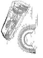
- FIG. 1 there is shown two examples of arch sections used in the production of an underground roadway support and lining.
- Each arch section 10 consists of prefabricated base and arch panels, wheth H r of steel or concrete, assembled together by, for example, bolting. Adjacent arch sections 10 can be butted and, for example, bolted together to provide a continuous support and lining for a mine roadway.
- Each arch section is constituted by two base panels 11 and two long arch panels 12. There may, alternatively, be three arch panels 12A, or four arch panels for example. Two or three arch panels are preferred.
- the length of the arch panels in the direction of curvature is selected to suit requirements.
- packing as indicated at 13 can be effected between the arch sections 10 and the earth strata 14.
- FIG. 4 there is shown a roadway supported and lined by arch sections 10 incorporating two arch panels 12 as illustrated in Fig. 1.
- guide rail 15 may be permanent or detachable for use in forward locations of the roadway as the support and lining advance.
- the apparatus for use in erecting the arch sections is a shuttle comprising at each side an elongate roller carriage 16 to each of which is connected an arcuate frame 17.
- the two frames 17 define an arch frame and at their junction slidably mount a pusher member 18.
- This pusher member 18 is engaged by an arm 19 of an erector handle 20 pivoted on one of the frames 17 and normally lying within the frame 17.
- the miners In use, when the roadway is sufficiently cleared for erection of another arch section, the miners locate on the arch frame 17 two arch panels 12 and they push the shuttle to a position where the arch frame 17 lies forwardly of the erected roadway cover and lining. They pull the handle 20 inwardly which causes the arm 19 to pivot upwardly and so cause the pusher member 18 to move upwardly and move the arch panels 12 into line with the immediately previously erected arch panels 12. The miners then butt the supported arch panels 12 against the erected arch panels 12 and bolt them together. The shuttle is now withdrawn and a base panel 11 inserted underneath and into butting relationship with each arch panel 1 2. The base and arch panels 11 and 12 are then bolted together. Finally, adjacent base panels 11 are bolted together.
- a second pusher member could be suitably linked to the handle 20 to act on the arch panel so that it is aligned over its entire arcuate length with the previously erected arch panel.
- the arch panels 12 may be bclted together before being elevated and will be bolted together if three arch panels are employed.
- the pusher member could be a pair of hydraulic rams operated remotely from a hydraulic power pack by a miner.
- the shuttle may be powered hydraulically along the track.
- a magazine may be built into the shuttle (see Fig. 5) by providing the carriage 16 along its length with arch frames 17 to receive and hold arch panels 12, only the forward arch frame 17 incorporating the arch panel elevating means.
- the pusher member is preferably a hydraulic ram arrangement 21 operated from a hydraulic pump 22 suitably coupled to a hydraulic power pack.
- Fig. 6 uhich shows a roadway with the arch construction broken away and with a shuttle incorporating a magazine generally indicated at 23.
- the prefabricated panels 11 and 12 are located above ground level onto trolleys 24. The latter arrive at the arch construction site by hoist and railway.
- the panels are transferred from the trolleys 24 to the magazine and shuttle unit 23 by a crawler base machine 25.
- the crawler base machine 25 is situated at the roadside and fitted to one side are two adjustable stabilizer arms 26. Normally the arms 26 will be , retracted and lie over the crawler track and when in use, they are at right angles to the machine body as shoun.
- the machine 25 is fitted with an extensible boom arm 27 at the end of which is a powered clamp 28 which positively locates and locks onto each arch panel 12.
- the clamp 28 is capable of 360° rotation.
- a power pack 29 for the crawler base machine 25 also supplies hydraulic power to the magazine and shuttle unit 23 via flexible hoses (not shown).
- the magazine and shuttle 23 instead of being mounted on guide rails may be mounted on a crawler base.
- powered facilities such as rams (not shown) to move the panels forward until they finally rest on the erector arch frame.
- This erector arch frame may comprise a ram-operated caliper-movement frame which when actuated, moves the complete arch frame outwards until it comes into contact with the ground strata.
- Within the caliper frame is provision to bring the panels together in union abutment, after which they are secured together.
- the base panels 11 may be either post-loaded and fitted with load bearing arrangements or lowered onto the floor position and possibly backfilled.
- the invention therefore also encompasses a mechanical handling system for use in a roadway support and lining erection and comprising a trolley for conveying the prefabficated panels from above ground to the roadway site, a panel-storage magazine and shuttle unit from which assembled arch panels are elevated into position against the strata to be supported, and a panel-transfer machine having a pivotal boom with a panel-clamp at one end for disposition between the trolley and magazine and shuttle unit.
- the arch support panel may be of a sufficient length to accommodate more than one pair of arch panels.
- the rails instead of being mounted along the base panels may be disposed on the ground.
Landscapes
- Engineering & Computer Science (AREA)
- Mining & Mineral Resources (AREA)
- Architecture (AREA)
- Civil Engineering (AREA)
- Structural Engineering (AREA)
- Life Sciences & Earth Sciences (AREA)
- General Life Sciences & Earth Sciences (AREA)
- Geochemistry & Mineralogy (AREA)
- Geology (AREA)
- Lining And Supports For Tunnels (AREA)
Applications Claiming Priority (2)
| Application Number | Priority Date | Filing Date | Title |
|---|---|---|---|
| GB7929943 | 1979-08-29 | ||
| GB7929943 | 1979-08-29 |
Publications (1)
| Publication Number | Publication Date |
|---|---|
| EP0025307A1 true EP0025307A1 (de) | 1981-03-18 |
Family
ID=10507478
Family Applications (1)
| Application Number | Title | Priority Date | Filing Date |
|---|---|---|---|
| EP80302941A Withdrawn EP0025307A1 (de) | 1979-08-29 | 1980-08-26 | Apparat und Verfahren zum Setzen von Streckenausbausegmenten |
Country Status (3)
| Country | Link |
|---|---|
| EP (1) | EP0025307A1 (de) |
| GB (1) | GB2057034A (de) |
| PL (1) | PL226478A1 (de) |
Cited By (6)
| Publication number | Priority date | Publication date | Assignee | Title |
|---|---|---|---|---|
| WO1986004952A1 (en) * | 1985-02-22 | 1986-08-28 | Allan Hilton Limited | An underground roadway support |
| EP0380409A1 (de) * | 1989-01-26 | 1990-08-01 | L'oreal | Verfahren zur Herstellung von nichtionischen grenzflächenaktiven Stoffen aus Isopropyliden-1,2-epoxypropyl-3-glycerol und aus hydroxylierten Verbindungen, nichtionische grenzflächenaktive Stoffe und Verwendung von diesen |
| WO2001075269A3 (en) * | 2000-03-31 | 2001-12-13 | Link Pipe Inc | Tunnel lining apparatus and method |
| US20100005751A1 (en) * | 2006-08-02 | 2010-01-14 | Guenther Troester | Substructure for a construction that is self-supporting without the substructure and use of the substructure |
| CN108661678A (zh) * | 2018-07-23 | 2018-10-16 | 中国铁建重工集团有限公司 | 隧道掘进设备及其支护系统 |
| CN112324472A (zh) * | 2020-11-21 | 2021-02-05 | 中铁一局集团有限公司 | 一种隧洞钢架支护结构及施工方法 |
Families Citing this family (3)
| Publication number | Priority date | Publication date | Assignee | Title |
|---|---|---|---|---|
| US4439066A (en) * | 1982-03-19 | 1984-03-27 | Mcnally Michael P | Pervious tunnel liner member |
| GB2157740B (en) * | 1984-04-18 | 1988-01-06 | British Steel Corp | Tunnel linings |
| CA2001469C (en) * | 1989-10-25 | 1994-05-17 | Pertti Tapani Raty | Mill hole liner ring connector assembly |
Citations (5)
| Publication number | Priority date | Publication date | Assignee | Title |
|---|---|---|---|---|
| US1388698A (en) * | 1918-07-22 | 1921-08-23 | Blawknox Company | Method of and apparatus for widening tunnels |
| GB1409022A (en) * | 1973-02-01 | 1975-10-08 | Coal Industry Patents Ltd | Mine roof support equipment |
| DE2542778B1 (de) * | 1975-09-25 | 1977-01-13 | Bochumer Eisen Heintzmann | Verfahren zum mechanisierten einbringen von streckenausbau und einrichtung zur durchfuehrung des verfahrens |
| DE2130219B2 (de) * | 1971-06-18 | 1978-08-31 | Bauunternehmung E. Heitkamp Gmbh, 4690 Herne | Vorrichtung zum Setzen eines aus einzelnen Segmenten bestehenden Tunnelausbaus |
| DE2802737A1 (de) * | 1978-01-23 | 1979-07-26 | Gutehoffnungshuette Sterkrade | Verfahren und vorrichtung zur durchfuehrung des verfahrens fuer den tunnel- und streckenvortrieb, insbesondere fuer strecken im untertagebetrieb mit streckenquerschnitten unter 20 m hoch 2 |
-
1980
- 1980-08-26 GB GB8027624A patent/GB2057034A/en not_active Withdrawn
- 1980-08-26 EP EP80302941A patent/EP0025307A1/de not_active Withdrawn
- 1980-08-29 PL PL22647880A patent/PL226478A1/xx unknown
Patent Citations (5)
| Publication number | Priority date | Publication date | Assignee | Title |
|---|---|---|---|---|
| US1388698A (en) * | 1918-07-22 | 1921-08-23 | Blawknox Company | Method of and apparatus for widening tunnels |
| DE2130219B2 (de) * | 1971-06-18 | 1978-08-31 | Bauunternehmung E. Heitkamp Gmbh, 4690 Herne | Vorrichtung zum Setzen eines aus einzelnen Segmenten bestehenden Tunnelausbaus |
| GB1409022A (en) * | 1973-02-01 | 1975-10-08 | Coal Industry Patents Ltd | Mine roof support equipment |
| DE2542778B1 (de) * | 1975-09-25 | 1977-01-13 | Bochumer Eisen Heintzmann | Verfahren zum mechanisierten einbringen von streckenausbau und einrichtung zur durchfuehrung des verfahrens |
| DE2802737A1 (de) * | 1978-01-23 | 1979-07-26 | Gutehoffnungshuette Sterkrade | Verfahren und vorrichtung zur durchfuehrung des verfahrens fuer den tunnel- und streckenvortrieb, insbesondere fuer strecken im untertagebetrieb mit streckenquerschnitten unter 20 m hoch 2 |
Cited By (7)
| Publication number | Priority date | Publication date | Assignee | Title |
|---|---|---|---|---|
| WO1986004952A1 (en) * | 1985-02-22 | 1986-08-28 | Allan Hilton Limited | An underground roadway support |
| EP0380409A1 (de) * | 1989-01-26 | 1990-08-01 | L'oreal | Verfahren zur Herstellung von nichtionischen grenzflächenaktiven Stoffen aus Isopropyliden-1,2-epoxypropyl-3-glycerol und aus hydroxylierten Verbindungen, nichtionische grenzflächenaktive Stoffe und Verwendung von diesen |
| WO2001075269A3 (en) * | 2000-03-31 | 2001-12-13 | Link Pipe Inc | Tunnel lining apparatus and method |
| US20100005751A1 (en) * | 2006-08-02 | 2010-01-14 | Guenther Troester | Substructure for a construction that is self-supporting without the substructure and use of the substructure |
| CN108661678A (zh) * | 2018-07-23 | 2018-10-16 | 中国铁建重工集团有限公司 | 隧道掘进设备及其支护系统 |
| CN112324472A (zh) * | 2020-11-21 | 2021-02-05 | 中铁一局集团有限公司 | 一种隧洞钢架支护结构及施工方法 |
| CN112324472B (zh) * | 2020-11-21 | 2022-04-08 | 中铁一局集团有限公司 | 一种隧洞钢架支护结构及施工方法 |
Also Published As
| Publication number | Publication date |
|---|---|
| PL226478A1 (de) | 1981-05-22 |
| GB2057034A (en) | 1981-03-25 |
Similar Documents
| Publication | Publication Date | Title |
|---|---|---|
| AU672163B1 (en) | Highwall mining apparatus | |
| US4474287A (en) | Variable length conveyor assembly | |
| EP0157286A1 (de) | Förderband-Anordnung für Kohlengewinnungsmaschine | |
| CN107060795A (zh) | 一种地下矿井tbm组装施工方法 | |
| EP0025307A1 (de) | Apparat und Verfahren zum Setzen von Streckenausbausegmenten | |
| US4687375A (en) | Circular heading machine | |
| CN209892217U (zh) | 快速掘进系统 | |
| US4269547A (en) | Tunnel roof supporting apparatus | |
| US20050067879A1 (en) | Combination panline and utility drilling or bolting unit | |
| JP3864377B2 (ja) | 既設トンネル拡幅工法 | |
| US3578809A (en) | Method and apparatus for forming subterranean structures | |
| AU570725B2 (en) | Circular heading machine | |
| EP2229505B1 (de) | Vorrichtung zur herstellung eines unterirdischen tunnels | |
| RU2026982C1 (ru) | Проходческий агрегат | |
| US3712071A (en) | Method and apparatus for forming subterranean structures | |
| GB2177033A (en) | Self-propelled roof drilling and bolting trolley | |
| US20090039695A1 (en) | Guide frame for guiding conveyor segments in high wall mining | |
| EP0383456A2 (de) | Setzen von Bogenausbau | |
| RU2098632C1 (ru) | Комплекс для ремонта горных выработок | |
| Krauze et al. | Operational Tests of a Modular Installation and Transport Assembly of Steel Arch Support in Underground Excavations | |
| SU1490302A1 (ru) | Перемычка дл предотвращени выбросов угл , породы и газа | |
| US9631491B2 (en) | Apparatus for forming an underground tunnel | |
| RU2163970C1 (ru) | Струговый комплекс, секция крепи, установка струговая, база струговая, привод струга, перегружатель укороченный, крепь сопряжения, манипулятор передвижной | |
| SU1213210A1 (ru) | Тоннельный рычажный крепеукладчик | |
| GB2223044A (en) | Setting mine roof arches |
Legal Events
| Date | Code | Title | Description |
|---|---|---|---|
| PUAI | Public reference made under article 153(3) epc to a published international application that has entered the european phase |
Free format text: ORIGINAL CODE: 0009012 |
|
| AK | Designated contracting states |
Designated state(s): AT BE DE FR GB IT |
|
| STAA | Information on the status of an ep patent application or granted ep patent |
Free format text: STATUS: THE APPLICATION IS DEEMED TO BE WITHDRAWN |
|
| 18D | Application deemed to be withdrawn |
Effective date: 19820212 |