EP0024980A1 - Self-cleaning apparatus for moulding plaster - Google Patents
Self-cleaning apparatus for moulding plaster Download PDFInfo
- Publication number
- EP0024980A1 EP0024980A1 EP80401198A EP80401198A EP0024980A1 EP 0024980 A1 EP0024980 A1 EP 0024980A1 EP 80401198 A EP80401198 A EP 80401198A EP 80401198 A EP80401198 A EP 80401198A EP 0024980 A1 EP0024980 A1 EP 0024980A1
- Authority
- EP
- European Patent Office
- Prior art keywords
- tank
- mixture
- casting
- cylinder
- hearth
- Prior art date
- Legal status (The legal status is an assumption and is not a legal conclusion. Google has not performed a legal analysis and makes no representation as to the accuracy of the status listed.)
- Granted
Links
- 239000011505 plaster Substances 0.000 title claims abstract description 22
- 238000004140 cleaning Methods 0.000 title abstract description 10
- 238000000465 moulding Methods 0.000 title 1
- 239000000203 mixture Substances 0.000 claims abstract description 36
- XLYOFNOQVPJJNP-UHFFFAOYSA-N water Substances O XLYOFNOQVPJJNP-UHFFFAOYSA-N 0.000 claims abstract description 9
- 238000005266 casting Methods 0.000 claims description 57
- 230000002787 reinforcement Effects 0.000 claims description 33
- 239000007788 liquid Substances 0.000 claims description 5
- 238000007789 sealing Methods 0.000 claims description 5
- 238000005452 bending Methods 0.000 claims description 4
- 238000006073 displacement reaction Methods 0.000 claims 1
- 238000011144 upstream manufacturing Methods 0.000 abstract description 6
- 238000004519 manufacturing process Methods 0.000 abstract description 4
- 238000000034 method Methods 0.000 abstract description 3
- 238000013019 agitation Methods 0.000 description 7
- 238000003860 storage Methods 0.000 description 5
- 239000011521 glass Substances 0.000 description 3
- 239000011324 bead Substances 0.000 description 2
- 238000009434 installation Methods 0.000 description 2
- 238000007711 solidification Methods 0.000 description 2
- 230000008023 solidification Effects 0.000 description 2
- 238000003756 stirring Methods 0.000 description 2
- 229910001018 Cast iron Inorganic materials 0.000 description 1
- 229910000831 Steel Inorganic materials 0.000 description 1
- 239000000835 fiber Substances 0.000 description 1
- 239000000945 filler Substances 0.000 description 1
- 239000006260 foam Substances 0.000 description 1
- 239000000463 material Substances 0.000 description 1
- 239000003607 modifier Substances 0.000 description 1
- 230000000149 penetrating effect Effects 0.000 description 1
- 230000000737 periodic effect Effects 0.000 description 1
- 230000002093 peripheral effect Effects 0.000 description 1
- 239000004033 plastic Substances 0.000 description 1
- 230000003014 reinforcing effect Effects 0.000 description 1
- 239000011347 resin Substances 0.000 description 1
- 229920005989 resin Polymers 0.000 description 1
- 230000000284 resting effect Effects 0.000 description 1
- 239000010959 steel Substances 0.000 description 1
- 239000000126 substance Substances 0.000 description 1
- 239000004094 surface-active agent Substances 0.000 description 1
- -1 thinners Substances 0.000 description 1
Images


Classifications
-
- B—PERFORMING OPERATIONS; TRANSPORTING
- B28—WORKING CEMENT, CLAY, OR STONE
- B28B—SHAPING CLAY OR OTHER CERAMIC COMPOSITIONS; SHAPING SLAG; SHAPING MIXTURES CONTAINING CEMENTITIOUS MATERIAL, e.g. PLASTER
- B28B23/00—Arrangements specially adapted for the production of shaped articles with elements wholly or partly embedded in the moulding material; Production of reinforced objects
- B28B23/0006—Arrangements specially adapted for the production of shaped articles with elements wholly or partly embedded in the moulding material; Production of reinforced objects the reinforcement consisting of aligned, non-metal reinforcing elements
-
- B—PERFORMING OPERATIONS; TRANSPORTING
- B28—WORKING CEMENT, CLAY, OR STONE
- B28B—SHAPING CLAY OR OTHER CERAMIC COMPOSITIONS; SHAPING SLAG; SHAPING MIXTURES CONTAINING CEMENTITIOUS MATERIAL, e.g. PLASTER
- B28B13/00—Feeding the unshaped material to moulds or apparatus for producing shaped articles; Discharging shaped articles from such moulds or apparatus
- B28B13/02—Feeding the unshaped material to moulds or apparatus for producing shaped articles
-
- B—PERFORMING OPERATIONS; TRANSPORTING
- B28—WORKING CEMENT, CLAY, OR STONE
- B28B—SHAPING CLAY OR OTHER CERAMIC COMPOSITIONS; SHAPING SLAG; SHAPING MIXTURES CONTAINING CEMENTITIOUS MATERIAL, e.g. PLASTER
- B28B5/00—Producing shaped articles from the material in moulds or on moulding surfaces, carried or formed by, in or on conveyors irrespective of the manner of shaping
- B28B5/02—Producing shaped articles from the material in moulds or on moulding surfaces, carried or formed by, in or on conveyors irrespective of the manner of shaping on conveyors of the endless-belt or chain type
- B28B5/026—Producing shaped articles from the material in moulds or on moulding surfaces, carried or formed by, in or on conveyors irrespective of the manner of shaping on conveyors of the endless-belt or chain type the shaped articles being of indefinite length
- B28B5/027—Producing shaped articles from the material in moulds or on moulding surfaces, carried or formed by, in or on conveyors irrespective of the manner of shaping on conveyors of the endless-belt or chain type the shaped articles being of indefinite length the moulding surfaces being of the indefinite length type, e.g. belts, and being continuously fed
Definitions
- the present invention relates to the manufacture of plaster objects, essentially in the form of a plate, and more specifically to the casting on a pouring floor movable in translation of a mixture of plaster and water contained in a bottomless tank. placed on said casting hearth.
- the mixture is introduced through the supply tubes with a certain speed, so as to create agitation in the tank and is vibrated the front and rear plates using vibrators mounted on the plates themselves; when reinforcements must be placed inside the products that we manufacture, in some cases we arrange to introduce said reinforcements by rubbing them on the lower edge of one and / or the other of the front plates and rear of the tank.
- the invention proposes to renew the rear wall, preferably continuously, without disturbing the pouring or the agitation.
- One solution to achieve this is to integrate it into a larger surface that is moved, periodically or continuously, so as to present a portion of different surface area in front of the tank, while the portion taken out of service is cleaned in waiting to be represented in front of the tank to play again the role of rear wall.
- this surface is materialized by a flat plate which is made to slide facing the casting tank; in other embodiments, the surface is curved and it is rotated to present a different portion facing the reservoir.
- This curved surface can be a rotating drum with a vertical axis, either of a diameter equal to the width of the casting hearth and then bearing on the lateral bands during their journey, or of a larger diameter and taking then press only on the ends of the side bands.
- the operations of renewing the rear plate, cleaning the rear plate and guiding the reinforcement are combined, constituting the curved surface of which the rear plate is a portion by a cylindrical roller. , of horizontal axis perpendicular to the direction of advancement of the casting hearth, and of width equal to that of this casting hearth.
- This cylinder is rotated, the reinforcement that one wishes to have in the poured product, introduced in support on its lower portion, rubs on it and cleans it.
- the cylinder is rotated in the opposite direction to the direction of progression of the reinforcement driven by the cast product.
- the speed of rotation of the roller or possibly the frequency and the angle of the rotation when it is discontinuous, are such that a point on its surface which comes into contact with the liquid mixture of plaster and water is put out of contact of the mixture and cleaned in a sufficiently short time so that the plaster deposited at this point does not have time to set.
- the front plate is given a domed shape with horizontal bending axis perpendicular to the direction of advance of the casting hearth and we introduce this reinforcement resting on this curved surface.
- the tubes for supplying new product are then independent of the front plate; the feed is done by a feed ramp arranged between the two front and rear plates as close as possible to the front plate.
- Figure 1 shows an installation for pouring a liquid mixture based on plaster and water.
- this mixture may contain other substances such as accelerators or retarders, reinforcing elements such as cut fibers, fillers, surfactants, thinners, resins, foams, etc. ., which will not be mentioned later, it will simply be called a mixture of plaster and water.
- the casting installation comprises a horizontal casting hearth 1, movable in translation in the direction of arrow F, two lateral strips 2 and 3 each rotating around two rollers 4 and 5 and forming vertical edges at the casting hearth, a front wall 6 in the form of a vertical plate perpendicular to the direction of advancement of the floor 1 and a rear plate 7 parallel to the front wall 6, bearing on the ends of the lateral bands 2 and 3.
- the rear plate 7 has a length sufficient to form at least two portions 7a and 7b arranged side by side, each capable of forming the rear wall of the casting tank e. It is slidably mounted on two vertical slides 8 and 9. Periodically, the plate 7 is slid in these slides so as to deactivate the portion which closed the tank, for example the portion 7a, and to replace it with the other, in this case the portion 7b. The portion 7a is then cleaned and it is ready to be put into service again in place of the portion 7b.
- the slides are high enough to allow the height positions of the plate 7 to be adjusted.
- the plate 7 may have its lower edge covered by a bead 10, or may carry a curved flap, directed outside the tank to guide the introduction of a reinforcement in the product that is manufactured.
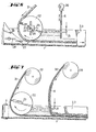
- FIG. 2 shows a pouring head of the same type but in which the rear wall of the tank is a cylindrical drum 11 with a vertical axis 12, the diameter of which is equal to the width of the casting sole 1.
- the axis 12 of this cylinder 11 is arranged so that the front of the cylinder, which acts as the rear wall of the casting tank, rests on the floor 1.
- the cylinder 11 is in contact by its two generators diametrically opposite with the side bands 2 and 3 and it has on its underside a seal 13 which seals with the casting hearth, 1.
- the axis 12 of the cylinder 11 is equipped with a pinion 14 connected by a chain 15 to a motor 16 for the rotation drive.
- these means are placed so as to act on the portion of cylinder wet with plaster which has just left the reservoir, that is to say near the side shown in the figure when the cylinder rotates in the direction of arrow I.
- this cylinder is suspended by its axis, and it can then be entirely located above the movable casting hearth.
- this advantageous assembly makes it possible to introduce a reinforcement into the product, near the lower surface, by causing it to arrive under the drum 11.
- a reinforcement introducer 19 independent, in the form of a horizontal and transverse bar, or curved shutter, will be arranged at the rear of the drum 11.
- the front plate 6 is surmounted by a vibrator 20 and it is crossed by tubes 21 for supplying the mixture.
- a vibrator 20 As also explained in this document, the front plate 6 is surmounted by a vibrator 20 and it is crossed by tubes 21 for supplying the mixture.
- the front wall 6 of the pouring tank can be curved so that the energy per unit volume of mixture contained in the tank, supplied by the jets through the supply tubes 21, s ' oit substantially the same in the center and on the edges of the tank.
- the drum 11 is supported on the ends of the side bands 2 and 3 and it is of larger diameter allowing to have a tank of practically rectangular surface, better agitated by the supply jets than the tank previous to two pointed corners, adjacent to the drum.
- the drums 11 are of thickness substantially equal to the height of the front plate, and at least sufficiently thick to contain the mixture without overflowing. They are mounted on slide so that their distance from the front plate can be adjusted and located at such a distance from the latter that the adjustments made in the case of a fixed and flat rear plate are not modified. The explanation of these settings will be given later.
- the cylinder 11 is rotated, either continuously or discontinuously, at a speed such that a point on its surface in contact with the plaster mixture at a given time either removed from the tank and cleaned by the cleaning means 17 and 18 before the plaster which has deposited there has had time to set, or times of the order of 2 min for a plaster without setting modifier.
- the curved surface of which a portion forms the rear wall of the casting tank is a cylindrical roller 22 with horizontal axis 23, of length equal to the distance between the side bands 2 and 3 so that the seal between said bands and the cylinder is obtained.
- the shaft of this cylinder rotates in bearings 24 mounted on a support with two slides 25, one vertical, the other horizontal so as to allow the height adjustment and the adjustment of the distance relative to the front plate.
- the axis of this roller 22 is connected to a motor 26 capable of driving it in rotation.
- a sealing shoe 27 having substantially the shape of a prism but the upper surface of which is concave can be placed at the rear of the roller 22.
- This sealing shoe 27 is mounted on horizontal slides 28 allowing its correct positioning.
- the roller 22 has a sufficiently large diameter so that its axis can pass over the side bands 2 and 3, so as to be supported and driven by the motor 26. A diameter of the order of 30 cm will be common. It may be a roll of cast iron, steel, plastic, etc., preferably a material which is not very porous and hard.
- the front plate can be given a domed shape with horizontal generatrixes perpendicular to the direction of advance of the casting hearth.
- this convex shape of the front plate can be envisaged with all the variants of rear wall: flat wall, drum wall with vertical axis or roll wall with horizontal axis .
- the roller 29 of storage of the reinforcement 30 that is introduced inside the tank is disposed in front of the front plate or at least vertically above it so that said reinforcement 30 rubs on the surface of said front plate 6.
- a ramp 35 independent of the front plate 6.
- the ramp 35 is a tube of length equal to the width of the casting head, provided with a row of orifices 36, connected in the middle of its length, by a tube 37, to the means producing the mixture of plaster and water.
- This ramp is disposed between the two front and rear plates of the bucket, parallel to said plates, as close as possible to the front plate, is immersed in the mixture so that the jets of mixture which it delivers through orifices 36 are submerged like the jets delivered by the tubes 21 through the front plate in the other embodiments, or placed immediately above the free surface of the liquid, with orifices 36 slightly inclined downwards so that the jets , while rapidly penetrating into the mixture, produce the necessary agitation.
- the orifices 36 are distributed like the supply tubes 21 which pass through the front plate in the other embodiments.
- the energies of all the jets exiting the ramp are identical, the sections of the orifices are growing from the middle of the ramp towards its ends.
- the procedure is as follows. First, the height of the roller 22 is adjusted relative to the casting floor 1 by adjusting the position of the bearings 24 on the vertical slides 25. The lower generator of the roller 22 must be at an equal distance from the casting floor at the height at which you want to position the reinforcement in the thickness of the product.
- the procedure is as if it were a flat and fixed rear plate; that is to say that once fixed the feed rate of the mixture for manufacturing products in plates of a given thickness at the chosen speed of the casting hearth, the number of feed tubes capable of producing agitation over the entire width of the head is determined casting, we determine the section of the supply tubes and pipes upstream so that the speed of mixing prohibits deposits, that is to say, is greater than 10 cm / s, we create the casting slot under the front plate 6, we adjust the distance from the front plate to the roller or rear drum so as to have, in the pouring tank, a stable mixing level and- submerged supply jets. Distances between the front plate and the front generator of the roller of the order of 10 cm will frequently be encountered.
- the reinforcements are then introduced by dispersing their storage rollers so that the reinforcements well sweep the surfaces which they are responsible for cleaning.
- a reinforcement 31 is passed under the roller 22 and then under the front plate 6.
- the reinforcement driven by the casting, stretches.
- the storage roller 32 of the reinforcement 31 is placed so that the reinforcement 31 winds at least a quarter and preferably a third of the rear roller 22.
- the reinforcement 31 will descend vertically until contact with roller 22.
- the sealing part 27 will be advanced under the roller 22 to stop this leak. It can be seen that with a roller 22 30 cm in diameter, spaced 6 mm from the casting hearth, under which passes a mat of entangled continuous wires 2.5 mm thick in the free state, with speeds from the 1.50 m to 3 m / min casting bottom, there is no leakage. The leak only appears if the space is increased by 1 or 2 mm.
- the speed of rotation of the roller 22 or of the drum 11 is then adjusted, so that a point on the roller does not remain in the plaster or covered with plaster without being cleaned for more than a time of the order of 2 min. , corresponding to the time necessary for the plaster to start setting.
- a mixing height of approximately 15 mm in the tank a peripheral speed between 1 cm / min and 10 cm / min will be suitable, and a speed of the order of 3 cm will be commonly chosen.
- the rotation speed should not be too high, so as not to disturb the casting. If the rotation is sequential, rotations will be made approximately every minute, at an angle such that the constraints already stated are respected.
- these grids are made up of orthogonal wires welded to each other, with all of the "warp” wires entirely on one side of the grid mid-plane, and all of the "weft” wires entirely of the other side of this same plane, we will choose to put in contact with the curved front wall those of the wires which will be the most transverse to the direction of travel of said grids, or in other words most parallel to the plane of the casting hearth, to favor cleaning this wall.
Landscapes
- Engineering & Computer Science (AREA)
- Manufacturing & Machinery (AREA)
- Chemical & Material Sciences (AREA)
- Ceramic Engineering (AREA)
- Mechanical Engineering (AREA)
- Devices For Post-Treatments, Processing, Supply, Discharge, And Other Processes (AREA)
- Detergent Compositions (AREA)
- Coating Apparatus (AREA)
- Containers And Packaging Bodies Having A Special Means To Remove Contents (AREA)
- Chain Conveyers (AREA)
- Producing Shaped Articles From Materials (AREA)
- Moulds For Moulding Plastics Or The Like (AREA)
- Cleaning Implements For Floors, Carpets, Furniture, Walls, And The Like (AREA)
- Working Measures On Existing Buildindgs (AREA)
- Continuous Casting (AREA)
- Fats And Perfumes (AREA)
- Cleaning By Liquid Or Steam (AREA)
- Electrical Discharge Machining, Electrochemical Machining, And Combined Machining (AREA)
Abstract
Description
La présente invention se rapporte à la fabrication d'objets en plâtre, essentiellement en forme de plaque, et plus précisément à la coulée sur une sole de coulée mobile en translation d'un mélange de plâtre et d'eau contenu dans un réservoir sans fond posé sur ladite sole de coulée.The present invention relates to the manufacture of plaster objects, essentially in the form of a plate, and more specifically to the casting on a pouring floor movable in translation of a mixture of plaster and water contained in a bottomless tank. placed on said casting hearth.
Il est connu par la publication de brevet français FR 2416 777 de constituer les parois latérales avant et arrière du réservoir à l'aide de deux plaques, et ses parois latérales à l'aide de bandes mobiles qui défilent comme la sole de coulée et qui prennent appui sur les extrémités des plaques avant et arrière. On alimente le réservoir par des tubes traversant la plaque avant, débouchant dans le réservoir et produisant des jets de mélange approxirativement horizontaux dirigés à contre-sens du sens d'avancement de la sole de coulée. La plaque avant est légèrement soulevée de façon à ménager une fente de coulée entre son arête inférieure et la sole de coulée. Pour éviter une prise en masse au sein même du produit contenu dans le réservoir et sur les parois dudit réservoir, on introduit le mélange par les tubes d'alimentation avec une certaine vitesse, de façon à créer une agitation dans le réservoir et on fait vibrer les plaques avant et arrière à l'aide de vibreurs montés sur les plaques mêmes ; lorsqu'on doit disposer des renforts à l'intérieur des produits qu'on fabrique, on s'arrange dans certains cas pour introduire lesdits renforts en les faisant frotter sur le rebord inférieur de l'une et/ou l'autre des plaques avant et arrière du réservoir. Dans la mesure où on règle la hauteur des tubes d'alimentation, la vitesse d'arrivée du mélange, l'écartement entre les deux plaques avant et arrière du réservoir, pour bien avoir, comme cela est décrit dans la demande précitée, des jets immergés mais provoquant des lignes d'agitation exécutant au moins un trajet aller de la plaque avant à la plaque arrière et un trajet retour en revenant jusqu'à la plaque avant, formant des boucles accolées couvrant toute la surface du réservoir, dans la mesure où on vibre les plaques avant et arrière, il ne se produit pas de dépôt pouvant entraîner des prises en masse et le dispositif de coulée, encore appelé par la suite tête de coulée, fonctionne sans intervention. Cependant si la tête de coulée n'est pas réglée au mieux, il y a quelques éclaboussures et il peut se former, essentiellement sur la plaque arrière, à proximité de la surface libre du mélange, en particulier entre les boucles d'agitation et dans les angles du réservoir, des dépôts qui nécessitent un certain nettoyage, sans toutefois obligation d'arrêt de la coulée, ceci d'autant plus fréquemment que le réglage est moins bon, par exemple toutes les deux ou trois heures. Malgré cet inconvénient d'exiger un-bon réglage ou à défaut un nettoyage périodique de la plaque arrière, des têtes de coulée d'une soixantaine de centimètres de large donnent satisfaction. Mais lorsque les dimensions augmentent, la principale difficulté est de maintenir les plaques en vibration, en particulier la plaque arrière sur laquelle se font principalement les dépôts.It is known from the publication of French patent FR 2416 777 to constitute the front and rear side walls of the tank using two plates, and its side walls using mobile bands which run like the casting floor and which are supported on the ends of the front and rear plates. The tank is supplied by tubes passing through the front plate, opening into the tank and producing approximately horizontal mixing jets directed against the direction of advancement of the casting hearth. The front plate is slightly raised so as to provide a casting slot between its lower edge and the casting hearth. To avoid solidification within the product contained in the tank and on the walls of said tank, the mixture is introduced through the supply tubes with a certain speed, so as to create agitation in the tank and is vibrated the front and rear plates using vibrators mounted on the plates themselves; when reinforcements must be placed inside the products that we manufacture, in some cases we arrange to introduce said reinforcements by rubbing them on the lower edge of one and / or the other of the front plates and rear of the tank. Insofar as the height of the feed tubes is adjusted, the speed of arrival of the mixture, the spacing between the two front and rear plates of the tank, so as to have, as described in the aforementioned application, submerged jets but causing stirring lines performing at least one outward path from the front plate to the rear plate and a return path returning to the front plate, forming contiguous loops covering the entire surface of the tank, since the front and rear plates are vibrated, no deposit occurs which can lead to solidification and the pouring device , also called the pouring head thereafter, operates without intervention. However, if the casting head is not adjusted to the best, there is some splashing and it can form, mainly on the back plate, near the free surface of the mixture, in particular between the stirring loops and in the angles of the tank, deposits which require a certain cleaning, without however obligation to stop the casting, this all the more frequently as the setting is less good, for example every two or three hours. Despite this drawback of requiring a good adjustment or, failing this, periodic cleaning of the back plate, pouring heads sixty centimeters wide are satisfactory. But when the dimensions increase, the main difficulty is to keep the plates in vibration, in particular the back plate on which the deposits are mainly made.
Pour pouvoir se passer éventuellement du vibrage, l'invention propose de renouveler la paroi arrière, de préférence d'une façon continue, sans perturber la coulée ni l'agitation. Une solution pour y parvenir est de l'intégrer dans une surface plus importante qu'on déplace, périodiquement ou en continu, de façon à présenter en face du réservoir une portion de surface différente, tandis que la portion mise hors- service est nettoyée en attendant d'être représentée en face du réservoir pour jouer à nouveau le rôle de paroi arrière.In order to be able to do without vibration, the invention proposes to renew the rear wall, preferably continuously, without disturbing the pouring or the agitation. One solution to achieve this is to integrate it into a larger surface that is moved, periodically or continuously, so as to present a portion of different surface area in front of the tank, while the portion taken out of service is cleaned in waiting to be represented in front of the tank to play again the role of rear wall.
Dans un mode de réalisation, cette surface est matérialisée par une plaque plane qu'on fait coulisser face au réservoir de coulée ; dans d'autres modes de réalisation, la surface est courbe et on la fait tourner pour présenter face au réservoir une portion différente. Cette surface courbe peut être un tambour tournant d'axe vertical, soit d'un diamètre égal à la largeur de la sole de coulée et prenant alors appui sur les bandes latérales au cours de leur trajet, soit d'un diamètre plus grand et prenant alors appui sur les seules extrémités des bandes latérales.In one embodiment, this surface is materialized by a flat plate which is made to slide facing the casting tank; in other embodiments, the surface is curved and it is rotated to present a different portion facing the reservoir. This curved surface can be a rotating drum with a vertical axis, either of a diameter equal to the width of the casting hearth and then bearing on the lateral bands during their journey, or of a larger diameter and taking then press only on the ends of the side bands.
Dans l'art antérieur, on a également proposé, pour renforcer les produits fabriqués, d'introduire en amont du réservoir ou dans ledit réservoir un renfort guidé par un introducteur de renfort ayant la forme soit d'un volet incurvé, soit d'un bourrelet arrondi. Cet introducteur de renfort peut être solidaire de la base de la plaque arrière du réservoir, ou fixé indépendamment en amont du réservoir.In the prior art, it has also been proposed, to reinforce the products produced, to introduce upstream of the tank or into said tank a reinforcement guided by a reinforcement introducer having the form of either a curved flap or a rounded bead. This reinforcement introducer may be integral with the base of the rear plate of the tank, or independently fixed upstream of the tank.
Dans une forme préférée de réalisation de l'invention, on combine les opérations de renouvellement de la plaque arrière, de nettoyage de la plaque arrière et de guidage du renfort, en constituant la surface courbe dont la plaque arrière est une portion par un rouleau cylindrique, d'axe horizontal perpendiculaire à la direction d'avancement de la sole de coulée, et de largeur égale à celle de cette sole de coulée. Ce cylindre est entrainé en rotation, le renfort qu'on désire disposer dans le produit coulé, introduit en appui sur sa portion inférieure, frotte dessus et la nettoie. De préférence, le cylindre est entrainé en rotation dans le sens inverse du sens de progression du renfort entrainé par le produit coulé. La vitesse de rotation du rouleau, ou éventuellement la fréquence et l'angle de la rotation lorsque celle-ci est discontinue, sont tels qu'un point de sa surface entré en contact avec le mélange liquide de plâtre et d'eau est mis hors de contact du mélange et nettoyé en un temps assez bref pour que le plâtre déposé en ce point n'ait pas le temps de faire prise.In a preferred embodiment of the invention, the operations of renewing the rear plate, cleaning the rear plate and guiding the reinforcement are combined, constituting the curved surface of which the rear plate is a portion by a cylindrical roller. , of horizontal axis perpendicular to the direction of advancement of the casting hearth, and of width equal to that of this casting hearth. This cylinder is rotated, the reinforcement that one wishes to have in the poured product, introduced in support on its lower portion, rubs on it and cleans it. Preferably, the cylinder is rotated in the opposite direction to the direction of progression of the reinforcement driven by the cast product. The speed of rotation of the roller, or possibly the frequency and the angle of the rotation when it is discontinuous, are such that a point on its surface which comes into contact with the liquid mixture of plaster and water is put out of contact of the mixture and cleaned in a sufficiently short time so that the plaster deposited at this point does not have time to set.
D'autre part, dans la mesure où un renfort peut être introduit à l'intérieur du réservoir, on donne à la plaque avant une forme bombée avec axe de bombage horizontal perpendiculaire à la direction d'avancement de la sole de coulée et on introduit ce renfort en appui sur cette surface bombée. Avantageusement, les tubes d'alimentation en produit neuf sont alors indépendants de la plaque avant ; l'alimentation se fait par une rampe d'alimentation disposée entre les deux plaques avant et arrière aussi près que possible de la plaque avant.On the other hand, insofar as a reinforcement can be introduced inside the tank, the front plate is given a domed shape with horizontal bending axis perpendicular to the direction of advance of the casting hearth and we introduce this reinforcement resting on this curved surface. Advantageously, the tubes for supplying new product are then independent of the front plate; the feed is done by a feed ramp arranged between the two front and rear plates as close as possible to the front plate.
L'invention sera maintenant décrite avec plus de détails en référence aux dessins qui représentent :
- Fig. 1 : Une tête de coulée avec plaque arrière coulissante,
- Fig. 2 : Une vue de dessus d'une tête de coulée à plaque arrière tournante,
- Fig. 3 : Une vue de dessus d'une seconde variante selon l'invention,
- Fig. 4 : Une vue de dessus d'une forme préférée de réalisation d'une tête de coulée selon l'invention,
- Fig. 5 : Une vue de côté de la tête de coulée montrée sur la figure 4
- Fig. 6 : Une variante de la tête de coulée des figures 4 et 5 équipée d'un organe d'étanchéité,
- Fig. 7 : Une autre variante avec plaque avant bombée pour l'introduction d'un renfort,
- Fig. 8 : Une tête de rampe d'alimentation indépendante.
- Fig. 1: A casting head with sliding back plate,
- Fig. 2: A top view of a casting head with a rotating back plate,
- Fig. 3: A top view of a second variant according to the invention,
- Fig. 4: A top view of a preferred embodiment of a casting head according to the invention,
- Fig. 5: A side view of the casting head shown in Figure 4
- Fig. 6: A variant of the pouring head of FIGS. 4 and 5 equipped with a sealing member,
- Fig. 7: Another variant with curved front plate for the introduction of a reinforcement,
- Fig. 8: An independent feed ramp head.
La figure 1 montre une installation de coulée d'un mélange liquide à base de plâtre et d'eau. Bien que ce mélange puisse renfermer d'autres substances telles que des accélérateurs ou des retardateurs de prise, des éléments de renfort tels que des fibres coupées, des charges, des tensio-actifs, des fluidifiants, des résines, des mousses, etc..., dont il ne sera plus fait mention par la suite, il sera simplement appelé mé-lange de plâtre et d'eau.Figure 1 shows an installation for pouring a liquid mixture based on plaster and water. Although this mixture may contain other substances such as accelerators or retarders, reinforcing elements such as cut fibers, fillers, surfactants, thinners, resins, foams, etc. ., which will not be mentioned later, it will simply be called a mixture of plaster and water.
L'installation de coulée comporte une sole de coulée 1 horizontale, mobile en translation dans le sens de la flèche F, deux bandes latérales 2 et 3 tournant chacune autour de deux galets 4 et 5 et formant des rebords verticaux à la sole de coulée, une paroi avant 6 en forme de plaque verticale perpendiculaire à la direction d'avancement de la sole 1 et une plaque arrière 7 parallèle à la paroi avant 6, en appui sur les extrémités des bandes latérales 2 et 3.The casting installation comprises a
Conformément à l'invention, la plaque arrière 7 a une longueur suffisante pour former au moins deux portions 7a et 7b disposées côte à côte, aptes chacune à former la paroi arrière du réservoir de coulé e. Elle est montée coulissante sur deux glissières verticales 8 et 9. Périodiquement, on glisse la plaque 7 dans ces glissières de façon à mettre hors service la portion qui fermait le réservoir, par exemple la portion 7a, et à la remplacer par l'autre, en l'occurrence la portion 7b. La portion 7a est alors nettoyée et elle est prête pour être à nouveau mise en service à la place de la portion 7b. Avantageusement, les glissières sont suffisamment hautes pour permettre d'ajuster les positions en hauteur de la plaque 7.According to the invention, the rear plate 7 has a length sufficient to form at least two
La plaque 7 peut avoir son arête inférieure recouverte par un bourrelet 10, ou peut porter-un volet incurvé, dirigé à l'extérieur du réservoir pour guider l'introduction d'un renfort dans le produit qu'on fabrique.The plate 7 may have its lower edge covered by a bead 10, or may carry a curved flap, directed outside the tank to guide the introduction of a reinforcement in the product that is manufactured.
La figure 2 montre une tête de coulée du même type mais dans laquelle la paroi arrière du réservoir est un tambour cylindrique 11 à axe 12 vertical, dont le diamètre est égal à la largeur de la sole de coulée 1. L'axe 12 de ce cylindre 11 est disposé de façon que l'avant du cylindre, qui fait office de paroi arrière du réservoir de coulée, repose sur la sole 1. Le cylindre 11 est en contact par ses deux génératrices diamétralement opposées avec les bandes latérales 2 et 3 et il possède sur sa face inférieure un joint 13 qui assure l'étanchéité avec la sole de coulée,1. L'axe 12 du cylindre 11 est équipé d'un pignon 14 relié par une chaine 15 à un moteur 16 pour l'entraînement en rotation. Des moyens de nettoyage de la surface du cylindre 11, tels un racleur 17 et/ou une pomme d'arrosage d'eau 18 débarrassent le cylindre des dépôts de plâtre. De préférence, ces moyens sont placés de façon à agir sur la portion de cylindre mouillée de plâtre qui vient juste de sortir du réservoir, c'est-à-dire près du côté montré par la figure quand le cylindre tourne dans le sens de la flèche I. Avantageusement, ce cylindre est suspendu par son axe, et il peut alors être entièrement situé au-dessus de la sole de coulée mobile. En outre, ce montage avantageux permet d'introduire un renfort dans le produit, à proximité de la surface inférieure, en le faisant arriver sous le tambour 11. A cet effet, comme dit dans la publication déjà citée, un introducteur de renfort 19, indépendant, en forme de barreau horizontal et transversal, ou de volet incurvé, sera disposé à l'arrière du tambour 11.FIG. 2 shows a pouring head of the same type but in which the rear wall of the tank is a
Comme expliqué également dans ce document, la plaque avant 6 est surmontée d'un vibrateur 20 et elle est traversée par des tubes 21 d'alimentation en mélange. Avec ce type de tambour, dès que le renfort devra être situé dans l'épaisseur du produit, c'est-à-dire ailleurs qu'à proximité immédiate de la face inférieure, il sera préférable de l'introduire soit à l'intérieur du réservoir, soit en aval du réservoir.As also explained in this document, the
Comme on le voit sur la figure 2, la paroi avant 6 du réservoir de coulée peut être incurvée pour que l'énergie par unité de volume de mélange contenu dans Yèdit réservoir, apportée par les jets au travers des tubes d'alimentation 21, s'oit sensiblement la même au centre et sur les bords du réservoir. On pourra également obtenir le même équilibrage d'énergie, sans incurver la paroi avant 6 mais en la conservant plane, si l'on augmente la section ou le nombre des tubes d'alimentation 21 vers les bords de ladite plaque.As can be seen in FIG. 2, the
Dans une variante montrée figure 3, le tambour 11 prend appui sur les extrémités des bandes latérales 2 et 3 et il est de diamètre plus important permettant d'avoir un réservoir de surface pratiquement rectangulaire, mieux agité par les jets d'alimentation que le réservoir précédent à deux coins en pointe, adjacents au tambour.In a variant shown in Figure 3, the
Dans ces deux variantes, les tambours 11 sont d'épaisseur sensiblement égale à la hauteur de la plaque avant, et au moins suffisamment épais pour contenir le mélange sans débordement. Ils sont montés sur glissière pour qu'on puisse ajuster leur écartement par rapport à la plaque avant et les situer à telle distance de cette dernière que les réglages faits dans le cas d'une plaque arrière fixe et plane ne soient pas modifiés. L'explication de ces réglages sera donnée plus loin.In these two variants, the
Dans l'une et l'autre variante, le cylindre 11 est entraîné en rotation, soit de façon continue, soit de façon discontinue, à une vitesse telle qu'un point de sa surface en contact avec le mélange de plâtre à un instant donné soit sorti du réservoir et nettoyé par les moyens de nettoyage 17 et 18 avant que le plâtre qui s'y est déposé ait eu le temps de faire prise, soit des temps de l'ordre de 2 mn pour un plâtre sans modificateur de prise.In both variants, the
Dans une réalisation plus avantageuse de l'invention, montrée dans les figures 4 à 6, la surface courbe dont une portion forme la paroi arrière du réservoir de coulée est un rouleau cylindrique 22 à axe 23 horizontal, de longueur égale à la distance entre les bandes latérales 2 et 3 de façon que l'étanchéité entre lesdites bandes et le cylindre soit obtenue. L'arbre de ce cylindre tourne dans des paliers 24 montés sur un support à deux glissières 25, l'une verticale, l'autre horizontale de façon à permettre le réglage en hauteur et le réglage de la distance par rapport à la plaque avant. L'axe de ce rouleau 22 est relié à un moteur 26 susceptible de l'entraîner en rotation. En outre, comme montré sur la figure 6, un sabot d'étanchéité 27 ayant sensiblement la forme d'un prisme mais dont la surface supérieure est concave peut être placé à l'arrière du rouleau 22. Ce sabot d'étanchéité 27 est monté sur des glissières horizontales 28 permettant sa mise en place correcte. Le rouleau 22 a un diamètre suffisamment important pour que son axe puisse passer au-dessus des bandes latérales 2 et 3, de façon à être soutenu et entrainé par le moteur 26. Un diamètre de l'ordre de 30 cm sera courant. Il pourra s'agir d'un rouleau en fonte, en acier, en matière plastique, etc..., de préférence une matière peu poreuse et dure.In a more advantageous embodiment of the invention, shown in FIGS. 4 to 6, the curved surface of which a portion forms the rear wall of the casting tank is a
Comme montré sur la figure 7, on peut donner à la plaque avant une forme bombée à génératrices horizontales et perpendiculaires à la direction d'avancement de la sole de coulée. Avantageuse lors de l'introduction d'un renfort par le réservoir de coulée, cette forme bombée de la plaque avant peut être envisagée avec toutes les variantes de paroi arrière : paroi plane, paroi en tambour à axe vertical ou paroi en rouleau à axe horizontal. Dans ce cas, le rouleau 29 de stockage du renfort 30 qu'on introduit à l'intérieur du réservoir est disposé en avant de la plaque avant ou au moins à l'aplomb de celle-ci de façon que ledit renfort 30 frotte sur la surface de ladite plaque avant 6. 1As shown in FIG. 7, the front plate can be given a domed shape with horizontal generatrixes perpendicular to the direction of advance of the casting hearth. Advantageous during the introduction of a reinforcement by the casting tank, this convex shape of the front plate can be envisaged with all the variants of rear wall: flat wall, drum wall with vertical axis or roll wall with horizontal axis . In this case, the
Avantageusement, lorsque le renfort 30 est trop épais et qu'il risque de perturber l'alimentation en mélange, empêchant l'agitation dans l'auget, on préfère alimenter ledit auget par une rampe 35 indépendante de la plaque avant 6. La rampe 35 est un tube de longueur égale à la largeur de la tête de coulée, muni d'une rangée d'orifices 36, relié au milieu de sa longueur, par un tube 37, aux moyens producteurs du mélange de plâtre et d'eau. Cette rampe est disposée entre les deux plaques avant et arrière de l'auget, parallèlement aux dites plaques, aussi près que possible de la plaque avant, soit immergée dans le mélange pour que les jets de mélange qu'elle délivre au travers des orifices 36 soient immergés comme les jets délivrés par les tubes 21 au travers de la plaque avant dans les autres modes de réalisation, soit placée immédiatement au-dessus de la surface libre du liquide, avec des orifices 36 légèrement inclinés vers le bas de façon que les jets, tout en pénétrant rapidement dans le mélange, produisent l'agitation nécessaire. Les orifices 36 sont distribués comme les tubes d'alimentation 21 qui passent au travers de la plaque avant dans les autres modes de réalisation. Avantageusement, pour que les énergies de tous les jets sortant de la rampe soient identiques, les sections des orifices vont en grandissant du milieu de la rampe vers ses extrémités.Advantageously, when the
Pour régler une tête de coulée telle que celle montrée sur les figures 4 à 8, on procède de la façon suivante. On règle d'abord la hauteur du rouleau 22 par rapport à la sole de coulée 1 par ajustement de la position des paliers 24 sur les glissières verticales 25. La génératrice inférieure du rouleau 22 doit se trouver à une distance de la sole de coulée égale à la hauteur à laquelle on désire positionner le renfort dans l'épaisseur du produit.To adjust a casting head such as that shown in FIGS. 4 to 8, the procedure is as follows. First, the height of the
Pour régler la distance entre le tambour arrière 11 ou le rouleau arrière 22 et la plaque avant 6, on procède comme s'il s'agissait d'une plaque arrière plane et fixe ;c'est-à-dire qu'une fois fixé le débit d'alimentation en mélange pour fabriquer des produits en plaques d'une épaisseur donnée à la vitesse choisie de la sole de coulée, on détermine le nombre de tubes d'alimentation susceptibles de produire une agitation sur toute la largeur de la tête de coulée, on détermine la section des tubes d'alimentation et des tuyaux en amont pour que la vitesse du mélange interdise les dépôts, c'est-à-dire soit supérieure à 10 cm/s, on crée la fente de coulée sous la plaque avant 6, on règle la distance de la plaque avant au rouleau ou tambour arrière de façon à avoir, dans le réservoir de coulée, un niveau de mélange stable et- des jets d'alimentation immergés. Des distances entre la plaque avant et génératrice antérieure du rouleau de l'ordre de 10 cm se rencontreront fréquemment.To adjust the distance between the
On introduit ensuite les renforts en dispersant leurs rouleaux de stockage de façon que les renforts balaient bien les surfaces qu'ils sont chargés de nettoyer. Ainsi, on fait passer un renfort 31 sous le rouleau 22 puis sous la plaque avant 6. Le renfort, entraîné par la coulée, se tend. On dispose le rouleau de stockage 32 du renfort 31 de façon que le renfort 31 enroule au minimum un quart et de préférence un tiers du rouleau arrière 22. Ainsi dans la position la plus reculée possible du rouleau de stockage 32, le renfort 31 descendra verticalement jusqu'au contact avec le rouleau 22.The reinforcements are then introduced by dispersing their storage rollers so that the reinforcements well sweep the surfaces which they are responsible for cleaning. Thus, a
Si le rouleau arrière 22 est espacé de la sole de coulée et si une fuite de mélange se produit, on avancera la pièce d'étanchéité 27 sous sous le rouleau 22 pour arrêter cette fuite. On constate qu'avec un rouleau 22 de 30 cm de diamètre, espacé de 6 mm de la sole de coulée, sous lequel passe un mat de fils continus enchevêtrés de 2,5 mm d'épaisseur à l'état libre, avec des vitesses de sole de coulée de 1,50 m à 3 m/mn, il ne se produit pas de fuite. La fuite n'apparaît que si l'on augmente l'espace de 1 ou 2 mm.If the
On règle ensuite la vitesse de rotation du rouleau 22 ou du tambour 11 en s'arrangeant pour qu'un point du rouleau ne reste pas dans le plâtre ou recouvert de plâtre sans être nettoyé plus d'un temps de l'ordre de 2 mn, correspondant au temps nécessaire pour que le plâtre commence sa prise. Ainsi, pour un rouleau arrière de 30 cm de diamètre, une hauteur de mélange d'environ 15 mm dans le réservoir, une vitesse périphérique comprise entre 1 cm/mn et 10 cm/mn conviendra, et une vitesse de l'ordre de 3 cm sera couramment choisie. La vitesse de rotation ne devra pas être trop élevée, pour ne pas perturber la coulée. Si la rotation est séquentielle, on effectuera des rotations ènviron toutes les minutes, d'un angle tel que les contraintes déjà énoncées soient respectées.The speed of rotation of the
Ensuite, de la même façon, si l'on désire introduire un renfort supplémentaire 30 à l'intérieur du réservoir entre la plaque avant et le rouleau ou le tambour arrière en employant une plaque avant bombée, on s'arrange pour que le renfort tendu depuis son rouleau de stockage 29 frotte sur la totalité de la surface de plaque avant en contact avec le mélange.Then, in the same way, if it is desired to introduce an
Dans la mesure où l'on utilise, pour renforcer les plaques de plâtre, un-ensemble constitué d'un mat de fils de verre continus, enchevêtrés, enfermé entre deux grilles de fils de verre à grandes mailles, 0,5 mm par exemple, c'est seulement une des grilles de fils de verre qu'on choisira d'introduire en contact avec la plaque avant bombée. Ainsi, du fait de la taille importante des mailles, l'alimentation par les tubes 21 et l'agitation dans le réservoir ne seront pas perturbées. En.outre, si ces grilles sont constituées de fils orthogonaux soudés les uns aux autres, avec tous les fils de "chaine" entièrement d'un côté du plan médian de la grille, et tous les fils de "trame" entièrement de l'autre côté de ce même plan, on choisira de mettre en contact avec la paroi avant bombée ceux des fils qui seront le plus transversaux à la direction de défilement desdites grilles, ou autrement dit le plus parallèlement au plan de la sole de coulée, pour favoriser le nettoyage de cette paroi.Insofar as one uses, to reinforce the plasterboards, a set consisting of a mat of continuous glass threads, entangled, enclosed between two grids of glass threads with large mesh, 0.5 mm for example , it is only one of the glass wire grids that we will choose to introduce in contact with the curved front plate. Thus, due to the large size of the meshes, the supply by the
Dans la mesure où le renfort introduit en contact avec la plaque avant devient trop épais et risque de perturber l'alimentation et l'agitation et où l'on préfère utiliser une alimentation par une rampe 35 indépendante de la plaque avant, si la rampe est immergée, elle peut nécessiter un léger nettoyage toutes les 2 ou 3 heures de fonctionnement; si elle n'est pas immergée elle ne se salit évidemment pas. Avec une telle rampe, les déterminations de débits, sections des orifices, seront faites de la même façon que s'il s'agissait de tubes 21 au travers de la plaque avant.Insofar as the reinforcement introduced in contact with the front plate becomes too thick and risks disturbing the feeding and agitation and where it is preferred to use a feeding by a
Ces dispositifs de coulée ont été décrits en prenant comme exemple un mélange à base de plâtre mais ils sont utilisables aussi pour couler des produits évolutifs autres que le plâtre et à fortiori des produits moins évolutifs ou non évolutifs.These casting devices have been described by taking a plaster-based mixture as an example, but they can also be used for pouring evolutionary products other than plaster and a fortiori less evolutive or non-evolutive products.
Claims (19)
Priority Applications (1)
| Application Number | Priority Date | Filing Date | Title |
|---|---|---|---|
| AT80401198T ATE4033T1 (en) | 1979-08-21 | 1980-08-20 | SELF-CLEANING DEVICE FOR CASTING PLASTER. |
Applications Claiming Priority (2)
| Application Number | Priority Date | Filing Date | Title |
|---|---|---|---|
| FR7921038A FR2463669A1 (en) | 1979-08-21 | 1979-08-21 | SELF-CLEANING DEVICE FOR CASTING THE PLASTER |
| FR7921038 | 1979-08-21 |
Publications (2)
| Publication Number | Publication Date |
|---|---|
| EP0024980A1 true EP0024980A1 (en) | 1981-03-11 |
| EP0024980B1 EP0024980B1 (en) | 1983-07-06 |
Family
ID=9228966
Family Applications (1)
| Application Number | Title | Priority Date | Filing Date |
|---|---|---|---|
| EP80401198A Expired EP0024980B1 (en) | 1979-08-21 | 1980-08-20 | Self-cleaning apparatus for moulding plaster |
Country Status (17)
| Country | Link |
|---|---|
| US (1) | US4345887A (en) |
| EP (1) | EP0024980B1 (en) |
| JP (1) | JPS5634413A (en) |
| AT (1) | ATE4033T1 (en) |
| AU (1) | AU540274B2 (en) |
| BR (1) | BR8005280A (en) |
| CA (1) | CA1164634A (en) |
| DE (1) | DE3064044D1 (en) |
| DK (1) | DK357780A (en) |
| ES (1) | ES494366A0 (en) |
| FR (1) | FR2463669A1 (en) |
| GR (1) | GR69665B (en) |
| IE (1) | IE50046B1 (en) |
| MX (1) | MX150741A (en) |
| PL (1) | PL125717B1 (en) |
| PT (1) | PT71716B (en) |
| ZA (1) | ZA805128B (en) |
Families Citing this family (5)
| Publication number | Priority date | Publication date | Assignee | Title |
|---|---|---|---|---|
| AT399308B (en) * | 1993-04-29 | 1995-04-25 | Eternit Werke Hatschek L | METHOD AND PLANTS FOR PRODUCING PRODUCTS CONTAINING FIBERS AND HYDRAULIC BINDING AGENTS |
| US7364676B2 (en) * | 2005-09-01 | 2008-04-29 | United States Gypsum Company | Slurry spreader for cementitious board production |
| DE102012103648A1 (en) * | 2012-04-25 | 2013-10-31 | Dieffenbacher GmbH Maschinen- und Anlagenbau | Method and doctor blade device for doctoring a resin paste onto a carrier film and a resin mat system for producing resin mats |
| US10639654B2 (en) | 2016-07-06 | 2020-05-05 | United States Gypsum Company | Gypsum slurry application modifier |
| CA3190250A1 (en) * | 2020-07-29 | 2022-02-03 | Joseph Norris | Apparatus and method for continuously casting a member from a settable material |
Citations (2)
| Publication number | Priority date | Publication date | Assignee | Title |
|---|---|---|---|---|
| US2230074A (en) * | 1939-04-07 | 1941-01-28 | Riegel Textile Corp | Tile manufacture |
| US3979171A (en) * | 1974-11-29 | 1976-09-07 | Nagy Robert H | Concrete plank machine with wire mesh guide |
Family Cites Families (22)
| Publication number | Priority date | Publication date | Assignee | Title |
|---|---|---|---|---|
| US1036125A (en) * | 1912-06-25 | 1912-08-20 | J B King & Co | Plaster-board machine. |
| US1489693A (en) * | 1922-09-25 | 1924-04-08 | United States Gypsum Co | Machine and method for making hardened-edged plaster board |
| US1719199A (en) * | 1925-10-12 | 1929-07-02 | Schumacher John | Apparatus for printing wall board |
| GB656846A (en) * | 1939-09-08 | 1951-09-05 | Magnani Alessandro | Improvements relating to the manufacture of fibrous cement sheets |
| US2393213A (en) * | 1943-02-27 | 1946-01-15 | Willard Storage Battery Co | Casting machine |
| US3109763A (en) * | 1955-09-20 | 1963-11-05 | Johns Manville Fiber Glass Inc | Method and apparatus for forming a fiber reinforced resin panel |
| US3235400A (en) * | 1961-03-22 | 1966-02-15 | Union Carbide Corp | Metering foam coating |
| US3167603A (en) * | 1961-03-31 | 1965-01-26 | Union Carbide Corp | Process and apparatus for producing laminated panels |
| US3276072A (en) * | 1963-09-11 | 1966-10-04 | Nylonge Corp | Apparatus for forming regenerated cellulose sponge |
| US3288275A (en) * | 1965-12-06 | 1966-11-29 | Koppers Co Inc | Method and apparatus for cleaning conveyor belts |
| US3532576A (en) * | 1966-06-20 | 1970-10-06 | Nat Gypsum Co | Apparatus for making gypsum board |
| US3541639A (en) * | 1967-01-23 | 1970-11-24 | Enroc Lab Dev Co | Apparatus for making an athletic mat member |
| US3462795A (en) * | 1967-09-18 | 1969-08-26 | Admiral Equipment Corp | Double belt for manufacture of panels and the like |
| US3697205A (en) * | 1969-07-02 | 1972-10-10 | Kaiser Aluminium Chem Corp | Mold system and apparatus for producing a composite panel |
| US3773452A (en) * | 1970-05-12 | 1973-11-20 | J Taga | Apparatus for molding thermoplastic materials |
| GB1329418A (en) * | 1970-05-26 | 1973-09-05 | Go Con Concrete Ltd | Dispensing of a material into a mould |
| US3832099A (en) * | 1971-08-24 | 1974-08-27 | Uniform Ag | Apparatus for producing polyurethane foam |
| US3832250A (en) * | 1972-07-24 | 1974-08-27 | Johns Manville | Method of forming gypsum boards with hardening edges |
| DE2344963A1 (en) * | 1972-09-11 | 1974-05-02 | Unifoam Ag | DEVICE FOR THE CONTINUOUS PRODUCTION OF POLYMER FOAM ROLLS |
| GB1431731A (en) * | 1973-01-18 | 1976-04-14 | Mitsubishi Rayon Co | Apparatus for continuously producing a sheet shaped product |
| US3867494A (en) * | 1973-03-06 | 1975-02-18 | Owens Corning Fiberglass Corp | Method and apparatus for producing fiber reinforced organic foam |
| SE386617B (en) * | 1974-11-20 | 1976-08-16 | Gullfiber Ab | DEVICE FOR THE PRODUCTION OF A CONTINUOUS STRING OF POROS THERMO PLASTIC |
-
1979
- 1979-08-21 FR FR7921038A patent/FR2463669A1/en active Granted
-
1980
- 1980-08-06 MX MX183463A patent/MX150741A/en unknown
- 1980-08-12 AU AU61390/80A patent/AU540274B2/en not_active Ceased
- 1980-08-19 PL PL1980226318A patent/PL125717B1/en unknown
- 1980-08-19 GR GR62695A patent/GR69665B/el unknown
- 1980-08-20 IE IE1755/80A patent/IE50046B1/en unknown
- 1980-08-20 EP EP80401198A patent/EP0024980B1/en not_active Expired
- 1980-08-20 DE DE8080401198T patent/DE3064044D1/en not_active Expired
- 1980-08-20 ES ES494366A patent/ES494366A0/en active Granted
- 1980-08-20 BR BR8005280A patent/BR8005280A/en unknown
- 1980-08-20 ZA ZA00805128A patent/ZA805128B/en unknown
- 1980-08-20 AT AT80401198T patent/ATE4033T1/en not_active IP Right Cessation
- 1980-08-20 DK DK357780A patent/DK357780A/en unknown
- 1980-08-20 PT PT71716A patent/PT71716B/en unknown
- 1980-08-21 JP JP11411580A patent/JPS5634413A/en active Pending
- 1980-08-21 CA CA000358729A patent/CA1164634A/en not_active Expired
- 1980-08-21 US US06/180,036 patent/US4345887A/en not_active Expired - Lifetime
Patent Citations (2)
| Publication number | Priority date | Publication date | Assignee | Title |
|---|---|---|---|---|
| US2230074A (en) * | 1939-04-07 | 1941-01-28 | Riegel Textile Corp | Tile manufacture |
| US3979171A (en) * | 1974-11-29 | 1976-09-07 | Nagy Robert H | Concrete plank machine with wire mesh guide |
Also Published As
| Publication number | Publication date |
|---|---|
| IE50046B1 (en) | 1986-02-05 |
| FR2463669A1 (en) | 1981-02-27 |
| MX150741A (en) | 1984-07-09 |
| ES8104039A1 (en) | 1981-04-01 |
| EP0024980B1 (en) | 1983-07-06 |
| ZA805128B (en) | 1981-09-30 |
| US4345887A (en) | 1982-08-24 |
| PL226318A1 (en) | 1981-09-04 |
| PT71716A (en) | 1980-09-01 |
| PT71716B (en) | 1981-06-25 |
| PL125717B1 (en) | 1983-06-30 |
| ATE4033T1 (en) | 1983-07-15 |
| DE3064044D1 (en) | 1983-08-11 |
| DK357780A (en) | 1981-02-22 |
| FR2463669B1 (en) | 1982-10-08 |
| AU540274B2 (en) | 1984-11-08 |
| CA1164634A (en) | 1984-04-03 |
| JPS5634413A (en) | 1981-04-06 |
| IE801755L (en) | 1981-02-21 |
| GR69665B (en) | 1982-07-07 |
| AU6139080A (en) | 1981-08-20 |
| ES494366A0 (en) | 1981-04-01 |
| BR8005280A (en) | 1981-03-04 |
Similar Documents
| Publication | Publication Date | Title |
|---|---|---|
| EP0270653B1 (en) | Device for continously cleaning and/or decontaminating a band of a thermoplastic film | |
| FR2519873A1 (en) | DEVICE FOR SEPARATING A LIQUID | |
| EP0003705A2 (en) | Method and device for manufacturing a plaster web or plaster panels and panels so produced | |
| FR2561059A1 (en) | DEVICE FOR SPREADING GRANULAR AND / OR PULVERULENT MATERIAL | |
| EP0024980B1 (en) | Self-cleaning apparatus for moulding plaster | |
| FR2490263A1 (en) | Mortar distributing hopper for bricklaying - includes hopper from which mortar is discharged via valve-controlled opening | |
| WO2006000703A1 (en) | Device for treating food products in a bath of liquid | |
| EP0714241B1 (en) | Device for continuously washing products, especially plant products | |
| EP3738909A1 (en) | Device for cleaning a conveyor belt by immersion in a bath of liquid subjected to ultrasonic waves | |
| EP0000004B1 (en) | Continuous filtration centrifuge for separation, washing or draining, and application to an automatic coffee machine | |
| FR2540742A1 (en) | FILTER DRUM OF A METALLURGICAL DAIRY FILTRATION FACILITY | |
| FR2671567A1 (en) | Machine for simultaneously spreading at least one solid material and a binder | |
| LU81865A1 (en) | PROCESS FOR THE CONTINUOUS MANUFACTURE OF A STEEL STRIP | |
| FR2581533A1 (en) | Method for washing low-density vegetable-garden plants and washing machine for implementing the method | |
| FR3120495A3 (en) | Water tank wall cleaning system with active rollers | |
| FR3096041A1 (en) | DEVICE FOR CLEANING A TRANSFER TAPE BY IMMERSION IN A BATH OF LIQUID SUBJECT TO ULTRASONIC WAVES | |
| FR2721235A1 (en) | Installation for treating metal strip, esp. for pickling rolled strip | |
| FR2677051A1 (en) | Method and machine for snow clearance of a traffic lane | |
| EP0100714B1 (en) | Method and device for filling a cheese basin for hard cheese | |
| FR2569718A1 (en) | Installation for gas production by fermentation of organic materials | |
| FR2474282A1 (en) | Runner bean cutting machine which eliminates waste of double cutting - by cutting only protruding ends of beans held in vertical tubes | |
| FR2729819A1 (en) | Automatic seeder, which tops up growing material in pot | |
| FR2483747A1 (en) | Mechanised salting of cheese rolls - in first peripheral and second lateral application station | |
| FR2725461A1 (en) | MACHINE FOR FORMING A LAYER OF PROTECTION OF THE PLATFORM OF A RAILWAY | |
| FR3096042A1 (en) | DEVICE FOR CLEANING A TRANSFER TAPE BY IMMERSION IN A BATH OF LIQUID SUBJECT TO ULTRASONIC WAVES |
Legal Events
| Date | Code | Title | Description |
|---|---|---|---|
| PUAI | Public reference made under article 153(3) epc to a published international application that has entered the european phase |
Free format text: ORIGINAL CODE: 0009012 |
|
| AK | Designated contracting states |
Designated state(s): AT BE CH DE GB IT LU NL |
|
| 17P | Request for examination filed |
Effective date: 19810731 |
|
| ITF | It: translation for a ep patent filed |
Owner name: DR. ING. A. RACHELI & C. |
|
| GRAA | (expected) grant |
Free format text: ORIGINAL CODE: 0009210 |
|
| AK | Designated contracting states |
Designated state(s): AT BE CH DE GB IT LI LU NL |
|
| REF | Corresponds to: |
Ref document number: 4033 Country of ref document: AT Date of ref document: 19830715 Kind code of ref document: T |
|
| REF | Corresponds to: |
Ref document number: 3064044 Country of ref document: DE Date of ref document: 19830811 |
|
| PGFP | Annual fee paid to national office [announced via postgrant information from national office to epo] |
Ref country code: LU Payment date: 19830817 Year of fee payment: 4 |
|
| PG25 | Lapsed in a contracting state [announced via postgrant information from national office to epo] |
Ref country code: LU Free format text: LAPSE BECAUSE OF NON-PAYMENT OF DUE FEES Effective date: 19830831 |
|
| REG | Reference to a national code |
Ref country code: CH Ref legal event code: PFA Free format text: ISOVER SAINT-GOBAIN |
|
| PLBE | No opposition filed within time limit |
Free format text: ORIGINAL CODE: 0009261 |
|
| STAA | Information on the status of an ep patent application or granted ep patent |
Free format text: STATUS: NO OPPOSITION FILED WITHIN TIME LIMIT |
|
| 26N | No opposition filed | ||
| PGFP | Annual fee paid to national office [announced via postgrant information from national office to epo] |
Ref country code: CH Payment date: 19840806 Year of fee payment: 5 |
|
| PGFP | Annual fee paid to national office [announced via postgrant information from national office to epo] |
Ref country code: BE Payment date: 19840930 Year of fee payment: 5 |
|
| PGFP | Annual fee paid to national office [announced via postgrant information from national office to epo] |
Ref country code: DE Payment date: 19841012 Year of fee payment: 5 |
|
| PGFP | Annual fee paid to national office [announced via postgrant information from national office to epo] |
Ref country code: AT Payment date: 19850731 Year of fee payment: 6 |
|
| PGFP | Annual fee paid to national office [announced via postgrant information from national office to epo] |
Ref country code: NL Payment date: 19850831 Year of fee payment: 6 |
|
| PG25 | Lapsed in a contracting state [announced via postgrant information from national office to epo] |
Ref country code: AT Effective date: 19860820 |
|
| PG25 | Lapsed in a contracting state [announced via postgrant information from national office to epo] |
Ref country code: LI Effective date: 19860831 Ref country code: CH Effective date: 19860831 |
|
| BERE | Be: lapsed |
Owner name: ISOVER SAINT-GOBAIN Effective date: 19860831 |
|
| PG25 | Lapsed in a contracting state [announced via postgrant information from national office to epo] |
Ref country code: NL Effective date: 19870301 |
|
| NLV4 | Nl: lapsed or anulled due to non-payment of the annual fee | ||
| REG | Reference to a national code |
Ref country code: CH Ref legal event code: PL |
|
| PG25 | Lapsed in a contracting state [announced via postgrant information from national office to epo] |
Ref country code: DE Effective date: 19870501 |
|
| GBPC | Gb: european patent ceased through non-payment of renewal fee | ||
| PG25 | Lapsed in a contracting state [announced via postgrant information from national office to epo] |
Ref country code: GB Free format text: LAPSE BECAUSE OF NON-PAYMENT OF DUE FEES Effective date: 19881118 |
|
| PG25 | Lapsed in a contracting state [announced via postgrant information from national office to epo] |
Ref country code: BE Effective date: 19890831 |