EP0024977B1 - Method and means for caging a vertical gyroscope - Google Patents
Method and means for caging a vertical gyroscope Download PDFInfo
- Publication number
- EP0024977B1 EP0024977B1 EP80401190A EP80401190A EP0024977B1 EP 0024977 B1 EP0024977 B1 EP 0024977B1 EP 80401190 A EP80401190 A EP 80401190A EP 80401190 A EP80401190 A EP 80401190A EP 0024977 B1 EP0024977 B1 EP 0024977B1
- Authority
- EP
- European Patent Office
- Prior art keywords
- axis
- rotation
- mass
- roll
- delay
- Prior art date
- Legal status (The legal status is an assumption and is not a legal conclusion. Google has not performed a legal analysis and makes no representation as to the accuracy of the status listed.)
- Expired
Links
Images

Classifications
-
- G—PHYSICS
- G01—MEASURING; TESTING
- G01C—MEASURING DISTANCES, LEVELS OR BEARINGS; SURVEYING; NAVIGATION; GYROSCOPIC INSTRUMENTS; PHOTOGRAMMETRY OR VIDEOGRAMMETRY
- G01C19/00—Gyroscopes; Turn-sensitive devices using vibrating masses; Turn-sensitive devices without moving masses; Measuring angular rate using gyroscopic effects
- G01C19/02—Rotary gyroscopes
- G01C19/04—Details
- G01C19/26—Caging, i.e. immobilising moving parts, e.g. for transport
-
- G—PHYSICS
- G01—MEASURING; TESTING
- G01C—MEASURING DISTANCES, LEVELS OR BEARINGS; SURVEYING; NAVIGATION; GYROSCOPIC INSTRUMENTS; PHOTOGRAMMETRY OR VIDEOGRAMMETRY
- G01C19/00—Gyroscopes; Turn-sensitive devices using vibrating masses; Turn-sensitive devices without moving masses; Measuring angular rate using gyroscopic effects
- G01C19/02—Rotary gyroscopes
- G01C19/44—Rotary gyroscopes for indicating the vertical
- G01C19/46—Erection devices for restoring rotor axis to a desired position
- G01C19/50—Erection devices for restoring rotor axis to a desired position operating by mechanical means
-
- G—PHYSICS
- G01—MEASURING; TESTING
- G01C—MEASURING DISTANCES, LEVELS OR BEARINGS; SURVEYING; NAVIGATION; GYROSCOPIC INSTRUMENTS; PHOTOGRAMMETRY OR VIDEOGRAMMETRY
- G01C25/00—Manufacturing, calibrating, cleaning, or repairing instruments or devices referred to in the other groups of this subclass
- G01C25/005—Manufacturing, calibrating, cleaning, or repairing instruments or devices referred to in the other groups of this subclass initial alignment, calibration or starting-up of inertial devices
-
- Y—GENERAL TAGGING OF NEW TECHNOLOGICAL DEVELOPMENTS; GENERAL TAGGING OF CROSS-SECTIONAL TECHNOLOGIES SPANNING OVER SEVERAL SECTIONS OF THE IPC; TECHNICAL SUBJECTS COVERED BY FORMER USPC CROSS-REFERENCE ART COLLECTIONS [XRACs] AND DIGESTS
- Y10—TECHNICAL SUBJECTS COVERED BY FORMER USPC
- Y10T—TECHNICAL SUBJECTS COVERED BY FORMER US CLASSIFICATION
- Y10T74/00—Machine element or mechanism
- Y10T74/12—Gyroscopes
- Y10T74/1204—Gyroscopes with caging or parking means
- Y10T74/1207—Rotor spin and cage release type
-
- Y—GENERAL TAGGING OF NEW TECHNOLOGICAL DEVELOPMENTS; GENERAL TAGGING OF CROSS-SECTIONAL TECHNOLOGIES SPANNING OVER SEVERAL SECTIONS OF THE IPC; TECHNICAL SUBJECTS COVERED BY FORMER USPC CROSS-REFERENCE ART COLLECTIONS [XRACs] AND DIGESTS
- Y10—TECHNICAL SUBJECTS COVERED BY FORMER USPC
- Y10T—TECHNICAL SUBJECTS COVERED BY FORMER US CLASSIFICATION
- Y10T74/00—Machine element or mechanism
- Y10T74/12—Gyroscopes
- Y10T74/1229—Gyroscope control
- Y10T74/1232—Erecting
- Y10T74/1236—Erecting by plural diverse forces
-
- Y—GENERAL TAGGING OF NEW TECHNOLOGICAL DEVELOPMENTS; GENERAL TAGGING OF CROSS-SECTIONAL TECHNOLOGIES SPANNING OVER SEVERAL SECTIONS OF THE IPC; TECHNICAL SUBJECTS COVERED BY FORMER USPC CROSS-REFERENCE ART COLLECTIONS [XRACs] AND DIGESTS
- Y10—TECHNICAL SUBJECTS COVERED BY FORMER USPC
- Y10T—TECHNICAL SUBJECTS COVERED BY FORMER US CLASSIFICATION
- Y10T74/00—Machine element or mechanism
- Y10T74/12—Gyroscopes
- Y10T74/1229—Gyroscope control
- Y10T74/1232—Erecting
- Y10T74/1243—Erecting by weight
-
- Y—GENERAL TAGGING OF NEW TECHNOLOGICAL DEVELOPMENTS; GENERAL TAGGING OF CROSS-SECTIONAL TECHNOLOGIES SPANNING OVER SEVERAL SECTIONS OF THE IPC; TECHNICAL SUBJECTS COVERED BY FORMER USPC CROSS-REFERENCE ART COLLECTIONS [XRACs] AND DIGESTS
- Y10—TECHNICAL SUBJECTS COVERED BY FORMER USPC
- Y10T—TECHNICAL SUBJECTS COVERED BY FORMER US CLASSIFICATION
- Y10T74/00—Machine element or mechanism
- Y10T74/12—Gyroscopes
- Y10T74/1282—Gyroscopes with rotor drive
-
- Y—GENERAL TAGGING OF NEW TECHNOLOGICAL DEVELOPMENTS; GENERAL TAGGING OF CROSS-SECTIONAL TECHNOLOGIES SPANNING OVER SEVERAL SECTIONS OF THE IPC; TECHNICAL SUBJECTS COVERED BY FORMER USPC CROSS-REFERENCE ART COLLECTIONS [XRACs] AND DIGESTS
- Y10—TECHNICAL SUBJECTS COVERED BY FORMER USPC
- Y10T—TECHNICAL SUBJECTS COVERED BY FORMER US CLASSIFICATION
- Y10T74/00—Machine element or mechanism
- Y10T74/12—Gyroscopes
- Y10T74/1286—Vertical gyroscopes
Definitions
- the present invention relates to a method of setting up a vertical gyroscope, as well as a gyroscope implementing this method.
- shift is meant the operational start-up of said gyroscope.
- the invention relates more particularly to gyroscopes for missiles, target vehicles, and unmanned flying vehicles.
- a vertical gyroscope or an artificial aircraft horizon essentially comprises a router or symmetrical mass of free revolution in rotation about an axis, a suspension assembly of said axis relative to the support of said gyroscope, means of driving in rotation of said router, and means for transducing the orientation of said axis, for example relative to the vertical.
- Said suspension assembly gives said axis, and therefore said router, a freedom of total or almost total angular position, while maintaining the center of gravity of the assembly relative to the support.
- the router When it is not spinning, the router is therefore in astatic equation and can occupy any angular position when it is launched in rotation. It is therefore necessary to readjust its position at this time, that is to say to bring its axis closer to that of the true vertical.
- the “chocked or readjusted” position of the router corresponds to the calibrated zeros of said transducer means.
- This operation is difficult to carry out when the machine or aircraft supporting the gyroscope is placed or temporarily fixed on a mobile support and animated by random movements during the recycling of the router, for example, when the gyroscope equips a missile fired from a ship or helicopter.
- the method for placing a gyroscopic device mounted on a mobile such as a missile, and comprising a mass of revolution rotating around an axis of rotation which should serve as a reference for vertical, means for suspending said mass making it possible to suspend said axis of rotation relative to the pitch axis and to the axis of roll of said mobile, motor means for driving said mass of revolution in rotation about its axis , means for rolling back said axis of rotation active when said mass does not rotate and a controllable mechanical erector system with a rotary pendulum driven, tending to automatically replace the axis of rotation of the mass of revolution on the vertical, method according to which the action of said roll return means is only suppressed with a first delay time with respect to the rotation of said mass of revolution is characterized in that one begins by putting in rotation the mass of revolution and this rotation is accelerated until the angular momentum of the mass in rotation is sufficient to ensure its stability, after which the action of said roll restoring means is suppress
- a gyroscope such as that of the invention, intended to be mounted on board a missile transported on a boat or a helicopter, is not started until after a certain time of navigation of the carrier vehicle; at that time, said carrier is in motion.
- Document FR-A-1 078 486 describes a gyroscopic device mounted on a mobile and comprising a mass of revolution rotating around an axis of rotation to be used as vertical reference, means for suspending said mass making it possible to suspending said axis of rotation relative to the pitch axis (or parallel thereto) and to the roll axis (or parallel thereto), an electric motor for driving the rotating mass and electric means active roll reminder when said mass does not rotate.
- a gyroscope is totally unsuitable for use on transported missiles.
- the starting of the router of the gyroscope described only begins with a delay of several seconds, which increases its time of setting up. It does not include blocking means outside the periods of use.
- the locking device can exert a restoring torque only in a very limited angular sector, which makes it inoperative for large deviations, in particular in the absence of the use of “Selsyns” detectors as torque motors.
- the constitution of this lock makes it unusable on a gyroscope. missiles transported due to the flexibility of the locking blade which would provide poor resistance to vibrations.
- the erector used cannot be controlled, and the movable balls which it comprises can take positions causing a certain imbalance, from where appearance of torques high enough to compromise the registration of the router, when starting such a router.
- gyroscope on a moving support even using “Selsyns” as torque motors.
- a device for implementing the method according to the invention mounted on a mobile, such as a missile, and comprising a mass of revolution rotating around an axis of rotation intended to serve as a vertical reference, means for suspension of said mass making it possible to suspend said axis of rotation with respect to the pitch axis and to the axis of roll of said mobile, motor means for driving said mass of revolution in rotation about its axis, return means in rolling of said axis of rotation active when said mass does not rotate and a mechanical rotary pendulum erector system tending to automatically replace the axis of rotation of the mass on the vertical, device in which said motor means and said return means are electric , is characterized in that the erector system comprises electrical control means, in that the motor means, the return means and the control means of said erector system are comma ndated in parallel from a common power source, in that a first delay device is arranged on the link between said source and said roll return means, this first delay being such that when it expires the ang
- the gyroscopic device comprises a router 1, enclosed in a housing 2 and capable of being rotated around its shaft 3 of axis ZZ 'by an electric motor 4 housed in said housing (see figure 4).
- the housing 2 comprises aligned pins 5 and 6, allowing it to pivot about the pitch axis Y-Y 'of the vehicle (not shown) on which said gyroscopic device is mounted.
- the pins 5 and 6 are used to articulate the housing 2 and its router 1 on a frame 7, itself articulated around the roll axis X-X 'of said vehicle.
- the frame 7 is not shown in FIG. 4.
- the supply and control connections of the motor 4 pass, in a known manner, through the pins 5 and 6 of the axis Y-Y 'and those (not shown) of the axis X-X' of the frame 7.
- the roll suspension frame 7 is integral with a cylindrical cam 8 on which rolls a roller 9 mounted free in rotation on an arm 10 articulated on an axis 11 integral with the housing 2 of said gyroscopic device.
- the cam 8 is centered on the roll axis X-X '.
- a spring 12 hooked between the end of the arm 10 opposite the roller 9, and said housing tends to apply with a determined force the roller 9 against the operating surface of the cam (position in dotted lines in FIG. 1).
- the shape of the cam 8 is such that when said roller 9 presses on its operative surface, the frame 7 is automatically brought back and maintained at the relative horizontal of the housing 2 (zero roll).
- An electromagnet 13 is capable of suppressing the action of the roller 9 when it is activated, by attracting against its frame 13a the arm 10 supporting the roller 9.
- the frame 13a and the winding 13b are made integral with the housing 2 by a casing 14.
- the roll frame 7 is free and, consequently, the router 1 is also free in roll.
- the roller 9 is applied to the cam 8 and causes said frame 7 and said router 1 to return and remain in the horizontal position relative to the machine supporting the gyroscopic device.
- the electromagnet 13 is activated in synchronism with the launching of the router by the motor 4.
- This spiral movement at start-up is caused by the component, around the axis XX ', of the reaction torque of the router motor 4, this component being all the more important as the angular difference around the axis YY 'is important when the motor is switched on 4.
- the set-up time of a vertical gyroscopic device reaches ten minutes.
- a delay t1 (of approximately 3 seconds for example) before releasing the frame 7 from the gyroscope and after having launched the router 1, the spiral movement is initially suppressed, thanks to the existence of the restoring torque around the axis XX ', which prevents the initiation of this spiral movement, while the angular momentum is still too low to ensure the stability of the gyroscope.
- the difference that is to say the gain on the stationing time, is a very important parameter in the case of an anti-ship weapon system for example, for which the reaction time of the system can constitute a decisive parameter.
- the introduction of the delay t1 on the same gyroscope reduces the set-up time from around ten minutes to around 2 minutes, which constitutes an interesting concrete result.
- the advantage is even more noticeable in the case of using the gyroscope on a carrier vehicle in oscillating motion with large angular amplitudes during the starting of the gyroscope (boat, plane or helicopter for example), because in this case, the 'resulting tilt at start around the XX axis' can bring the gyroscope into a configuration where its erection system can be made ineffective - or in any case, very ineffective -, which leads to a set-up time prohibitive, whereas, according to the invention, the gyroscope remains usable with a set-up time of a few minutes, even with a support having oscillation amplitudes of 30 ° around the horizontal.
- FIGS. 2 to 5 a known erector mechanism for a gyroscopic device has been illustrated, the roll return device 8 to 14 not being shown in these figures.
- this erector mechanism for a vertical gyroscopic device essentially comprises an unstable pendulum 15 articulated around the axis of rotation ZZ of the router 1, this unstable pendulum being driven in the same direction as the router 1 by a gear reducer 16 which is driven from the shaft 3 and which rotates at a constant speed of approximately 40 revolutions per minute, when the router rotates for example at 23,000 revolutions per minute, a counterweight 17 similar in shape to pendulum 1, articulated around the same axis, and above all of equivalent mass, so as to constitute with it a set whose center of gravity is located on the axis of rotation ZZ 'of the router, when the pendulum is unstable 15 is aligned with the counterweight 17.
- the latter case is carried out when the gyroscope is stabilized vertically and the erection system then does not apply any torque to the gyroscope. This is the case illustrated schematically in FIG. 2.
- the unstable pendulum 15 In its plane of rotation, perpendicular to the axis of rotation ZZ of the router 1, the unstable pendulum 15 has a freedom of angular movement between, on the one hand, a drive stop 18 which positions it at alignment with its counterweight 17, and, on the other hand, a front stop 19 which limits its free travel in the direction of the rotational movement of the gyroscopic system.
- the supply connections of the coil 20 are routed to the outside of the gyroscope suspension passing successively through the pins 5 and 6 of the internal axis Y-Y ', then through the pins (not shown) of the suspension axis X-X '.
- the unstable pendulum 15 (which turns extremely slowly at the start of the start of the router 1) could be, for a non-negligible time, in a position where it would exert a fairly large torque on the gyroscope, which would still have only a very low angular momentum; in this case, the gyroscope could reach a very difficult - if not impossible - position to then be corrected by the erector.
- t2 For a router reaching its maximum speed after a time of 90 seconds, you can choose t2 equal to 30 seconds.
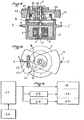
- FIG. 6 gives the block diagram of the control of the gyroscope according to the invention.
- the power supply 23 when the power supply 23 is activated by the command 24, it delivers a current to the motor 4 of the router 1, then to the electromagnet 13 deactivating the roll-back torque with 3 seconds of delay, then to l electromagnet 20 activating said erector with 30 seconds delay.
- the device according to the invention can be easily mounted on any gyroscope not intended to receive it, and in particular on simple commercial gyroscopes originally having a prohibitive shift time for use on missiles.
Landscapes
- Engineering & Computer Science (AREA)
- Physics & Mathematics (AREA)
- General Physics & Mathematics (AREA)
- Radar, Positioning & Navigation (AREA)
- Remote Sensing (AREA)
- Manufacturing & Machinery (AREA)
- Control Of Position, Course, Altitude, Or Attitude Of Moving Bodies (AREA)
- Gyroscopes (AREA)
Description
4 La présente invention concerne un procédé de mise à poste d'un gyroscope de verticale, ainsi qu'un gyroscope mettant en application ce procédé.4 The present invention relates to a method of setting up a vertical gyroscope, as well as a gyroscope implementing this method.
Par « mise à poste », on entend la mise en fonctionnement opérationnel dudit gyroscope. L'invention concerne plus particulièrement les gyroscopes pour missiles, engins-cibles, et engins volants non pilotés.By “shift” is meant the operational start-up of said gyroscope. The invention relates more particularly to gyroscopes for missiles, target vehicles, and unmanned flying vehicles.
On sait qu'un gyroscope de verticale ou un horizon artificiel d'aéronef comprend essentiellement une toupie ou masse symétrique de révolution libre en rotation autour d'un axe, un montage de suspension dudit axe par rapport au support dudit gyroscope, des moyens d'entraînement en rotation de ladite toupie, et des moyens transducteurs de l'orientation dudit axe, par exemple par rapport à la verticale. Ledit montage de suspension confère audit axe, et donc à ladite toupie, une liberté de position angulaire totale, ou quasi totale, tout en maintenant fixe le centre de gravité de l'ensemble par rapport au support.It is known that a vertical gyroscope or an artificial aircraft horizon essentially comprises a router or symmetrical mass of free revolution in rotation about an axis, a suspension assembly of said axis relative to the support of said gyroscope, means of driving in rotation of said router, and means for transducing the orientation of said axis, for example relative to the vertical. Said suspension assembly gives said axis, and therefore said router, a freedom of total or almost total angular position, while maintaining the center of gravity of the assembly relative to the support.
Lorsqu'elle ne tourne pas, la toupie est donc en équfflbn3 astatique et peut occuper n'importe quelle position angulaire au moment de son lancement en rotation. Il y a donc lieu de recaler sa position à ce moment, c'est-à-dire de rapprocher son axe de celui de la verticale vraie. La position « calée ou « recalée de la toupie correspond aux zéros étalonnés desdits moyens transducteurs.When it is not spinning, the router is therefore in astatic equation and can occupy any angular position when it is launched in rotation. It is therefore necessary to readjust its position at this time, that is to say to bring its axis closer to that of the true vertical. The “chocked or readjusted” position of the router corresponds to the calibrated zeros of said transducer means.
Cette opération est délicate à réaliser lorsque l'engin ou l'aéronef supportant le gyroscope est posé ou provisoirement fixé sur un support mobile et animé de mouvements aléatoires pendant le recyclage de la toupie, par exemple, lorsque le gyroscope équipe un missile tiré depuis un navire ou un hélicoptère.This operation is difficult to carry out when the machine or aircraft supporting the gyroscope is placed or temporarily fixed on a mobile support and animated by random movements during the recycling of the router, for example, when the gyroscope equips a missile fired from a ship or helicopter.
C'est pourquoi, notamment dans le cas d'utilisation décrit ci-avant, deux éléments sont ajoutés aux gyroscopes :
- - un mécanisme établissant un léger couple de rappel en roulis de l'ensemble mobile en roulis, lorsque la toupie est arrêtée (action sur le cadre externe qui, par la suite, est considéré comme cadre de roulis) ;
- - et un mécanisme érecteur replaçant ladite toupie automatiquement en position verticale dès que celle-ci est entraînée par des moyens moteurs.
- - a mechanism establishing a slight roll-back torque of the mobile roll assembly, when the router is stopped (action on the external frame which, thereafter, is considered to be a roll frame);
- - And an erector mechanism placing said router automatically in a vertical position as soon as it is driven by motor means.
Cependant la présence du mécanisme de rappel en roulis et du mécanisme érecteur ne supprime pas toutes les difficultés comme cela est expliqué par la suite.However, the presence of the roll-back mechanism and the erector mechanism does not eliminate all the difficulties as explained below.
Aussi, pour remédier à ces inconvénients, le procédé pour la mise à poste d'un dispositif gyroscopique monté sur un mobile, tel qu'un missile, et comportant une masse de révolution tournant autour d'un axe de rotation devant servir de référence de verticale, des moyens de suspension de ladite masse permettant de suspendre ledit axe de rotation par rapport à l'axe de tangage et à l'axe de roulis dudit mobile, des moyens moteurs pour entraîner ladite masse de révolution en rotation autour de son, axe, des moyens de rappel en roulis dudit axe de rotation actifs lorsque ladite masse ne tourne pas et un système érecteur mécanique commandable à pendule rotatif entraîné, tendant à replacer automatiquement l'axe de rotation de la masse de révolution sur la verticale, procédé selon lequel on ne supprime l'action desdits moyens de rappel en roulis qu'avec un premier temps de retard par rapport à la mise en rotation de ladite masse de révolution est caractérisé en ce que l'on commence par mettre en rotation la masse de révolution et on accélère cette rotation jusqu'à ce que le moment cinétique de la masse en rotation soit suffisant pour assurer la stabilité de celle-ci, après quoi on supprime l'action desdits moyens de rappel en roulis à l'expiration dudit premier temps de retard et en ce que ledit système érecteur n'est rendu actif qu'avec un second temps de retard par rapport à la mise en rotation de ladite masse de révolution ce second temps de retard étant plus grand que le premier et étant tel qu'à son expiration le moment cinétique et la vitesse de rotation du pendule sont suffisants pour réduire le mouvement du dispositif autour de son axe de roulis, dû au mouvement de précession de l'axe de rotation de la masse de révolution autour de la verticale.Also, to remedy these drawbacks, the method for placing a gyroscopic device mounted on a mobile, such as a missile, and comprising a mass of revolution rotating around an axis of rotation which should serve as a reference for vertical, means for suspending said mass making it possible to suspend said axis of rotation relative to the pitch axis and to the axis of roll of said mobile, motor means for driving said mass of revolution in rotation about its axis , means for rolling back said axis of rotation active when said mass does not rotate and a controllable mechanical erector system with a rotary pendulum driven, tending to automatically replace the axis of rotation of the mass of revolution on the vertical, method according to which the action of said roll return means is only suppressed with a first delay time with respect to the rotation of said mass of revolution is characterized in that one begins by putting in rotation the mass of revolution and this rotation is accelerated until the angular momentum of the mass in rotation is sufficient to ensure its stability, after which the action of said roll restoring means is suppressed expiration of said first delay time and in that said erector system is only made active with a second delay time relative to the rotation of said mass of revolution this second delay time being greater than the first and being such that at its expiration the angular momentum and the speed of rotation of the pendulum are sufficient to reduce the movement of the device around its roll axis, due to the precession movement of the axis of rotation of the mass of revolution around from the vertical.
Un gyroscope, tel que celui de l'invention, destiné à être monté à bord d'un missile transporté sur un bateau ou un hélicoptère, n'est démarré qu'après un certain temps de navigation de l'engin porteur ; à ce moment là, ledit porteur est en mouvement.A gyroscope, such as that of the invention, intended to be mounted on board a missile transported on a boat or a helicopter, is not started until after a certain time of navigation of the carrier vehicle; at that time, said carrier is in motion.
Dans le document FR-A-1 078 486, on décrit un dispositif gyroscopique monté sur un mobile et comportant une masse de révolution tournant autour d'un axe de rotation à utiliser comme référence de verticale, des moyens de suspension de ladite masse permettant de suspendre ledit axe de rotation par rapport à l'axe de tangage (ou parallèle à celui-ci) et à l'axe de roulis (ou parallèle à celui-ci), un moteur électrique pour entraîner la masse en rotation et des moyens électriques de rappel en roulis actifs lorsque ladite masse ne tourne pas. Cependant, un tel gyroscope est totalement impropre à une utilisation sur missiles transportés.Document FR-A-1 078 486 describes a gyroscopic device mounted on a mobile and comprising a mass of revolution rotating around an axis of rotation to be used as vertical reference, means for suspending said mass making it possible to suspending said axis of rotation relative to the pitch axis (or parallel thereto) and to the roll axis (or parallel thereto), an electric motor for driving the rotating mass and electric means active roll reminder when said mass does not rotate. However, such a gyroscope is totally unsuitable for use on transported missiles.
En effet, selon le brevet FR-A-1 078 486, le démarrage de la toupie du gyroscope décrit ne commence qu'avec un retard de plusieurs secondes, ce qui accroît son temps de mise à poste. Il ne comporte pas de moyens de blocage en dehors des périodes d'utilisation. Le dispositif de verrouillage ne peut exercer un couple de rappel que dans un secteur angulaire très limité, ce qui le rend inopérant pour des écarts importants, notamment en l'absence d'utilisation des détecteurs « Selsyns comme moteurs-couple. De plus, la constitution de ce verrouillage le rend inutilisable sur un gyroscope. de missiles transportés du fait de la souplesse de la lame de verrouillage qui procurerait une mauvaise tenue aux vibrations.In fact, according to patent FR-A-1 078 486, the starting of the router of the gyroscope described only begins with a delay of several seconds, which increases its time of setting up. It does not include blocking means outside the periods of use. The locking device can exert a restoring torque only in a very limited angular sector, which makes it inoperative for large deviations, in particular in the absence of the use of “Selsyns” detectors as torque motors. In addition, the constitution of this lock makes it unusable on a gyroscope. missiles transported due to the flexibility of the locking blade which would provide poor resistance to vibrations.
L'érecteur utilisé ne peut pas être commandé, et les billes mobiles qu'il comporte peuvent prendre des positions provoquant un certain balourd, d'où apparition de couples assez élevés pour compromettre le recalage de la toupie, lors du démarrage d'un tel gyroscope sur un support en mouvement, même en utilisant les « Selsyns » comme moteurs-couple.The erector used cannot be controlled, and the movable balls which it comprises can take positions causing a certain imbalance, from where appearance of torques high enough to compromise the registration of the router, when starting such a router. gyroscope on a moving support, even using “Selsyns” as torque motors.
Un dispositif pour la mise en oeuvre du procédé selon l'invention, monté sur un mobile, tel qu'un missile, et comportant une masse de révolution tournant autour d'un axe de rotation devant servir de référence à la verticale, des moyens de suspension de ladite masse permettant de suspendre ledit axe de rotation par rapport à l'axe de tangage et à l'axe de roulis dudit mobile, des moyens moteurs pour entraîner ladite masse de révolution en rotation autour de son axe, des moyens de rappel en roulis dudit axe de rotation actifs lorsque ladite masse ne tourne pas et un système érecteur mécanique à pendule rotatif entraîné tendant à replacer automatiquement l'axe de rotation de la masse sur la verticale, dispositif dans lequel lesdits moyens moteurs et lesdits moyens de rappel sont électriques, est caractérisé en ce que le système érecteur comporte des moyens de commande électrique, en ce que les moyens moteurs, les moyens de rappel et les moyens de commande dudit système érecteur sont commandés en parallèle à partir d'une source d'alimentation commune, en ce qu'un premier dispositif à retard est disposé sur la liaison entre ladite source et lesdits moyens de rappel en roulis, ce premier retard étant tel qu'à son expiration le moment cinétique de la masse en rotation est suffisant pour assurer la stabilité de celle-ci, et en ce qu'un second dispositif à retard est disposé sur la liaison entre ladite source et lesdits moyens de commande du système érecteur, ce second retard étant tel qu'à son expiration la vitesse de rotation du pendule est suffisante pour réduire le mouvement de précession du dispositif autour de son axe de roulis.A device for implementing the method according to the invention, mounted on a mobile, such as a missile, and comprising a mass of revolution rotating around an axis of rotation intended to serve as a vertical reference, means for suspension of said mass making it possible to suspend said axis of rotation with respect to the pitch axis and to the axis of roll of said mobile, motor means for driving said mass of revolution in rotation about its axis, return means in rolling of said axis of rotation active when said mass does not rotate and a mechanical rotary pendulum erector system tending to automatically replace the axis of rotation of the mass on the vertical, device in which said motor means and said return means are electric , is characterized in that the erector system comprises electrical control means, in that the motor means, the return means and the control means of said erector system are comma ndated in parallel from a common power source, in that a first delay device is arranged on the link between said source and said roll return means, this first delay being such that when it expires the angular momentum of the rotating mass is sufficient to ensure its stability, and in that a second delay device is arranged on the link between said source and said erector system control means, this second delay being such that at its expiration the speed of rotation of the pendulum is sufficient to reduce the precession movement of the device around its roll axis.
Les figures du dessin annexé feront bien comprendre comment l'invention peut être réalisée.
- La figure 1 illustre schématiquement le principe de moyens connus pour le rappel en roulis de l'équipage de suspension d'une toupie rotative d'un dispositif gyroscopique.
- Les figures 2 et 3 illustrent schématiquement le principe de moyens érecteurs connus pour amener automatiquement ladite toupie. en position verticale dès que celle-ci est entraînée par ses moyens moteurs, les figures 2 et 3 montrant respectivement l'axe de la toupie en position verticale et en position écartée de la verticale.
- La figure 4 montre, en coupe diamétrale, un exemple de réalisation de moyens érecteurs asso- . ciés à une toupie et à son boîtier.
- La figure 5 est une vue de dessus du dispositif de la figure 4.
- Figure 1 schematically illustrates the principle of known means for the roll back of the suspension crew of a spinning top of a gyroscopic device.
- Figures 2 and 3 schematically illustrate the principle of known erector means for automatically bringing said router. in the vertical position as soon as the latter is driven by its motor means, FIGS. 2 and 3 respectively showing the axis of the router in the vertical position and in the position away from the vertical.
- Figure 4 shows, in diametral section, an embodiment of associated erector means. ciés a spinning top and its housing.
- FIG. 5 is a top view of the device of FIG. 4.
Le dispositif gyroscopique, de type connu et montré sur le dessin, comporte une toupie 1, enfermée dans un boîtier 2 et susceptible d'être entraînée en rotation autour de son arbre 3 d'axe Z-Z' par un moteur électrique 4 logé dans ledit boîtier (voir la figure 4). Le boîtier 2 comporte des tourillons alignés 5 et 6, lui permettant de pivoter autour de l'axe de tangage Y-Y' du véhicule (non représenté) sur lequel est monté ledit dispositif gyroscopique.The gyroscopic device, of known type and shown in the drawing, comprises a
Les tourillons 5 et 6 servent à articuler le boîtier 2 et sa toupie 1 sur un cadre 7, lui-même articulé autour de l'axe de roulis X-X' dudit véhicule. Le cadre 7 n'est pas représenté sur la figure 4.The
Les connexions d'alimentation et de commande du moteur 4 passent, de façon connue, à travers les tourillons 5 et 6 de l'axe Y-Y' et ceux (non représentés) de l'axe X-X' du cadre 7.The supply and control connections of the
Le cadre 7 de suspension en roulis est solidaire d'une came cylindrique 8 sur laquelle roule un galet 9 monté libre en rotation sur un bras 10 articulé sur un axe 11 solidaire du boîtier 2 dudit dispositif gyroscopique. La came 8 est centrée sur l'axe de roulis X-X'. Un ressort 12 accroché entre l'extrémité du bras 10 opposée au galet 9, et ledit boîtier tend à appliquer avec une force déterminée le galet 9 contre la surface opérative de la came (position en pointillés sur la figure 1). La forme de la came 8 est telle que lorsque ledit galet 9 appuie sur sa surface opérative, le cadre 7 est automatiquement ramené et maintenu à l'horizontale relative du boîtier 2 (roulis nul). Un électro-aimant 13 est susceptible de supprimer l'action du galet 9 lorsqu'il est activé, en attirant contre son armature 13a le bras 10 supportant le galet 9. L'armature 13a et l'enroulement 13b sont rendus solidaires du boîtier 2 par un carter 14.The
Lorsque l'électro-aimant 13 est activé, le cadre de roulis 7 est libre et, par suite, la toupie 1 est libre également en roulis. Lorsqu'il est désactivé, le galet 9 s'applique sur la came 8 et fait revenir et rester ledit cadre 7 et ladite toupie 1 à la position horizontale relative à l'engin supportant le dispositif gyroscopique.When the
Dans la technique connue, l'électro-aimant 13 est activé en synchronisme avec le lancement de la toupie par le moteur 4.In the known technique, the
Par suite, le couple de rappel autour de l'axe X-X' est supprimé en même temps que la mise en rotation de la toupie 1 et il apparaît très souvent un mouvement en spirale de ladite toupie au départ, ce qui a pour inconvénient de laisser subsister un écart important autour de l'axe X-X', cet écart - qui dépasse parfois 50° - ne pouvant être corrigé ensuite que par le travail de l'érecteur.As a result, the restoring torque around the axis XX 'is eliminated at the same time as the rotation of the
Ce mouvement en spirale au démarrage est provoqué par la composante, autour de l'axe X-X', du couple de réaction du moteur de toupie 4, cette composante étant d'autant plus importante que l'écart angulaire autour de l'axe Y-Y' est important au moment de la mise sous tension du moteur 4.This spiral movement at start-up is caused by the component, around the axis XX ', of the reaction torque of the
Il en résulte que le temps de mise à poste d'un dispositif gyroscopique de verticale atteint une dizaine de minutes.As a result, the set-up time of a vertical gyroscopic device reaches ten minutes.
En introduisant, conformément à la présente invention, un retard t1 (d'environ 3 secondes par exemple) avant de libérer le cadre 7 du gyroscope et après avoir lancé la toupie 1, on supprime le mouvement en spirale au départ, grâce à l'existence du couple de rappel autour de l'axe X-X', qui empêche l'amorce de ce mouvement en spirale, alors que le moment cinétique est encore trop faible pour assurer la stabilité du gyroscope. La différence, c'est-à-dire le gain sur le temps de mise à poste, est un paramètre très important dans le cas d'un système d'arme anti-navire par exemple, pour lequel le temps de réaction du système peut constituer un paramètre décisif. On peut dire que l'introduction du retard t1 sur le même gyroscope fait passer le temps de mise à poste d'une dizaine de minutes à 2 minutes environ, ce qui constitue un résultat concret intéressant.By introducing, in accordance with the present invention, a delay t1 (of approximately 3 seconds for example) before releasing the
L'avantage est encore plus sensible dans le cas d'utilisation du gyroscope sur un véhicule porteur en mouvement d'oscillation avec des amplitudes angulaires importantes pendant le démarrage du gyroscope (bateau, avion ou hélicoptère par exemple), car dans ce cas, l'inclinaison résultante au démarrage autour de l'axe X-X' peut amener le gyroscope dans une configuration où son système d'érection peut être rendu inefficace - ou en tout cas, très peu efficace -, ce qui conduit à un temps de mise à poste prohibitif, alors que, selon l'invention, le gyroscope reste utilisable avec un temps de mise à poste de quelques minutes, même avec un support présentant des amplitudes d'oscillation de 30° autour de l'horizontale.The advantage is even more noticeable in the case of using the gyroscope on a carrier vehicle in oscillating motion with large angular amplitudes during the starting of the gyroscope (boat, plane or helicopter for example), because in this case, the 'resulting tilt at start around the XX axis' can bring the gyroscope into a configuration where its erection system can be made ineffective - or in any case, very ineffective -, which leads to a set-up time prohibitive, whereas, according to the invention, the gyroscope remains usable with a set-up time of a few minutes, even with a support having oscillation amplitudes of 30 ° around the horizontal.
Sur les figures 2 à 5, on a illustré un mécanisme érecteur connu pour dispositif gyroscopique, le dispositif de rappel en roulis 8 à 14, n'étant pas représenté sur ces figures.In FIGS. 2 to 5, a known erector mechanism for a gyroscopic device has been illustrated, the roll return device 8 to 14 not being shown in these figures.
Comme le montrent les figures 4 et 5, ce mécanisme érecteur pour dispositif gyroscopique de verticale comprend essentiellement, un pendule instable 15 articulé autour de l'axe de rotation ZZ de la toupie 1, ce pendule instable étant entraîné dans le même sens que la toupie 1 par un réducteur à engrenages 16 qui est entraîné à partir de l'arbre 3 et qui fait tourner à vitesse constante d'environ 40 tours par minute, lorsque la toupie tourne par exemple à 23 000 tours par minute, un contre-poids 17 de forme analogue au pendule 1, articulé autour du même axe, et surtout de masse équivalente, de façon à constituer avec lui un ensemble dont le centre de gravité est situé sur l'axe de rotation ZZ' de la toupie, quand le pendule instable 15 est aligné avec le contre-poids 17. Ce dernier cas est réalisé lorsque le gyroscope est stabilisé à la verticale et le système d'érection n'applique alors aucun couple au gyroscope. C'est le cas illustré schématiquement par la figure 2.As shown in FIGS. 4 and 5, this erector mechanism for a vertical gyroscopic device essentially comprises an
Dans son plan de rotation, perpendiculaire à l'axe de rotation ZZ de la toupie 1, le pendule Instable 15 dispose d'une liberté de débattement angulaire entre, d'une part, une butée d'entraînement 18 qui le positionne à l'alignement avec son contrepoids 17, et, d'autre part, une butée avant 19 qui limite sa course libre dans le sens du mouvement de rotation du système gyroscopique.In its plane of rotation, perpendicular to the axis of rotation ZZ of the
Dans cette dernière position du pendule (voir la figure 3) le système d'érection, n'étant plus équilibré, applique un couple au dispositif gyroscopique, ce qui a pour résultat de redresser l'axe de rotation ZZ' vers la position verticale V-V' s'il s'en était écarté.In this last pendulum position (see Figure 3) the erection system, no longer balanced, applies a torque to the gyroscopic device, which results in straightening the axis of rotation ZZ 'towards the vertical position VV 'if he had deviated from it.
En effet, on voit sur la figure 3 qu'en cas d'inclinaison de l'axe de rotation Z-Z' du gyroscope, dès le franchissement du point haut de la ligne de plus grande pente, le pendule instable 15 tombe contre sa butée avant 19 et s'y maintient ensuite jusqu'au franchissement du point bas de la ligne de plus grande pente du plan de rotation. A ce point bas, il attend le passage de sa butée arrière d'entraînement 18 qui le force à parcourir le demi-tour suivant (en montée m) à la vitesse constante de 40 tours par minute imposée par l'ensemble moteur 4-réducteur 16 ; après quoi, le phénomène recommence à chaque tour de l'érecteur, et à chaque tour le pendule 15 descend (descente d) donc plus rapidement qu'il ne monte de l'autre côté.In fact, it can be seen in FIG. 3 that in the event of inclination of the axis of rotation ZZ ′ of the gyroscope, as soon as the highest point of the line of greatest slope is crossed, the
On voit que le couple résultant appliqué au gyroscope (par cette différence entre les durées de descente d et de montée m du pendule) a toujours un effet redresseur en moyenne sur un tour, c'est-à-dire, qu'il tend à chaque tour à réduire l'écart entre l'axe de rotation ZZ' et la verticale V-V'.We see that the resulting torque applied to the gyroscope (by this difference between the durations of descent d and ascent m of the pendulum) always has a rectifying effect on average over one revolution, that is to say, that it tends to each turn to reduce the difference between the axis of rotation ZZ 'and the vertical V-V'.
Pour faciliter la représentation de la figure 3, on a supposé un grand écart autour de l'axe interne Y-Y' seulement ; bien entendu, le système d'érection agit à partir d'une inclinaison très faible inférieure même à 0,1° et d'autre part, l'effet redresseur reste valable pour toute orientation de l'inclinaison par rapport à la verticale et en particulier dans le cas d'une inclinaison composée autour des deux axes de suspension Y-Y' et X-X' en même temps.To facilitate the representation of FIG. 3, a large deviation has been assumed around the internal axis Y-Y 'only; of course, the erection system acts from a very low inclination even less than 0.1 ° and on the other hand, the rectifying effect remains valid for any orientation of the inclination relative to the vertical and in particularly in the case of a compound inclination around the two suspension axes YY 'and XX' at the same time.
En pratique, le fonctionnement est le suivant (voir figures 4 et 5) :
- En l'absence de courant dans une bobine 20 solidaire du boîtier 2 et concentrique à l'axe Z-Z',
un ressort 21maintient un cliquet 22 dans sa position basse pour laquelle il bloque le pendule instable 15 contre sa butée arrière 18 ; le système d'érection n'applique alors aucun couple sur le gyroscope puisque le centre de gravité de tout l'ensemble suspendu se trouve au point de rencontre des deux axes de suspension dont l'axe interne est Y-Y'.
- In the absence of current in a
coil 20 integral with thehousing 2 and concentric with the axis Z-Z ', aspring 21 maintains apawl 22 in its low position for which it blocks theunstable pendulum 15 against itsrear stop 18; the erection system then does not apply any torque to the gyroscope since the center of gravity of the entire suspended assembly is at the meeting point of the two suspension axes whose internal axis is Y-Y '.
Quand on alimente la bobine 20 sous une tension suffisante pour provoquer l'attraction de la palette mobile liée au cliquet 22, celui-ci vient occuper la position haute représentée sur la figure 4 et le pendule instable 15 retrouve alors sa liberté de débattement angulaire, ce qui permet à l'érecteur de fonctionner. La mise sous tension de la bobine permet donc de commander la mise en fonctionnement de l'érecteur du gyroscope.When the
Bien entendu, les connexions d'alimentation de la bobine 20 sont acheminées vers l'extérieur de la suspension du gyroscope en passant successivement par les tourillons 5 et 6 de l'axe interne Y-Y', puis par les tourillons (non représentés) de l'axe de suspension X-X'.Of course, the supply connections of the
Avec un tel érecteur mécanique connu, il est avantageux conformément à l'invention, pour la mise à poste du gyroscope, de ne commander l'érection qu'avec un retard t2 sur la mise en fonctionnement du moteur 4 de la toupie 1, ce retard t2 devant être assez grand pour permettre à l'érecteur de tourner à une vitesse suffisante.With such a known mechanical erector, it is advantageous according to the invention, for setting up the gyroscope, to control the erection only with a delay t2 on the starting of the
Sans ce retard t2, en effet, le pendule instable 15 (qui tourne extrêmement lentement au début du démarrage de la toupie 1) pourrait se trouver, pendant un temps non négligeable, dans une position où il exercerait un couple assez important sur le gyroscope, qui ne disposerait encore que d'un très faible moment cinétique ; dans ce cas, le gyroscope pourrait atteindre une position très difficile - voire même impossible - à corriger ensuite par l'érecteur.Without this delay t2, in fact, the unstable pendulum 15 (which turns extremely slowly at the start of the start of the router 1) could be, for a non-negligible time, in a position where it would exert a fairly large torque on the gyroscope, which would still have only a very low angular momentum; in this case, the gyroscope could reach a very difficult - if not impossible - position to then be corrected by the erector.
Avec le retard t2, au contraire, l'érecteur étant neutralisé, il ne s'exerce aucun couple de balourd sur le gyroscope pendant le temps correspondant.With the delay t2, on the contrary, the erector being neutralized, no unbalance torque is exerted on the gyroscope during the corresponding time.
Pour une toupie atteignant son régime maximal après un temps de 90 secondes, on peut choisir t2 égal à 30 secondes.For a router reaching its maximum speed after a time of 90 seconds, you can choose t2 equal to 30 seconds.
La figure 6 donne le schéma synoptique de la commande du gyroscope selon l'invention.FIG. 6 gives the block diagram of the control of the gyroscope according to the invention.
Une alimentation électrique 23 est activée par une commande 24. Ladite alimentation est reliée parallèlement :
- -
au moteur 4 de la toupie 1 du gyroscope, - -à l'électro-
aimant 13 désactivant le couple de rappel en roulis de la suspension de ladite toupie par l'intermédiaire d'un relais 25 temporisé par exemple à 3 secondes, - - à l'électro-
aimant d'activation 20 de l'érecteur, par l'intermédiaire d'un relais temporisé 26, par exemple à 30 secondes.
- - to the
motor 4 of therouter 1 of the gyroscope, - to the
electromagnet 13 deactivating the roll-back torque of the suspension of said router by means of arelay 25 timed for example at 3 seconds, - - to the
activation electromagnet 20 of the erector, via atime relay 26, for example at 30 seconds.
Ainsi, lorsque l'alimentation 23 est activée par la commande 24, elle délivre un courant au moteur 4 de la toupie 1, puis à l'électro-aimant 13 désactivant le couple de rappel en roulis avec 3 secondes de retard, puis à l'électro-aimant d'activation 20 dudit érecteur avec 30 secondes de retard.Thus, when the
Il en résulte alors un fonctionnement permettant de réduire le temps de mise à poste du gyroscope dans de grandes proportions (2 minutes au lieu de 10 minutes), résultat obtenu habituellement avec un matériel très sophistiqué dont le prix peut atteindre vingt fois celui d'un matériel comprenant l'équipement selon l'invention. ,This then results in an operation making it possible to reduce the time for setting up the gyroscope in large proportions (2 minutes instead of 10 minutes), a result usually obtained with very sophisticated equipment whose price can reach twenty times that of a material comprising the equipment according to the invention. ,
Le dispositif selon l'invention peut être monté facilement sur tout gyroscope non prévu pour le recevoir, et notamment sur les gyroscopes simples du commerce présentant originellement un temps de mise à poste prohibitif pour utilisation sur missiles.The device according to the invention can be easily mounted on any gyroscope not intended to receive it, and in particular on simple commercial gyroscopes originally having a prohibitive shift time for use on missiles.
Claims (2)
Applications Claiming Priority (2)
| Application Number | Priority Date | Filing Date | Title |
|---|---|---|---|
| FR7922006A FR2464457A1 (en) | 1979-09-03 | 1979-09-03 | METHOD AND DEVICE FOR PLACING A VERTICAL GYROSCOPE |
| FR7922006 | 1979-09-03 |
Publications (3)
| Publication Number | Publication Date |
|---|---|
| EP0024977A2 EP0024977A2 (en) | 1981-03-11 |
| EP0024977A3 EP0024977A3 (en) | 1981-03-18 |
| EP0024977B1 true EP0024977B1 (en) | 1983-07-13 |
Family
ID=9229307
Family Applications (1)
| Application Number | Title | Priority Date | Filing Date |
|---|---|---|---|
| EP80401190A Expired EP0024977B1 (en) | 1979-09-03 | 1980-08-13 | Method and means for caging a vertical gyroscope |
Country Status (5)
| Country | Link |
|---|---|
| US (1) | US4346614A (en) |
| EP (1) | EP0024977B1 (en) |
| CA (1) | CA1136906A (en) |
| DE (1) | DE3064132D1 (en) |
| FR (1) | FR2464457A1 (en) |
Families Citing this family (1)
| Publication number | Priority date | Publication date | Assignee | Title |
|---|---|---|---|---|
| WO1983001681A1 (en) * | 1981-11-09 | 1983-05-11 | Navidyne Corp | Improved gyro-stabilized apparatus |
Family Cites Families (9)
| Publication number | Priority date | Publication date | Assignee | Title |
|---|---|---|---|---|
| US2737052A (en) * | 1956-03-06 | noxon | ||
| US2605641A (en) * | 1952-08-05 | Starting arrangement for gyro | ||
| US2891407A (en) * | 1959-06-23 | Gyroscopic apparatus | ||
| US2654254A (en) * | 1949-07-20 | 1953-10-06 | Gen Electric | Caging device for gyroscopes |
| FR1078486A (en) * | 1952-03-14 | 1954-11-18 | Sperry Corp | Gyroscopic instrument with centering and locking device for the rotor support frame |
| US2729978A (en) * | 1952-11-18 | 1956-01-10 | Iron Fireman Mfg Co | Gyroscope caging system |
| US2907212A (en) * | 1957-04-03 | 1959-10-06 | Air Equipment | Gyroscopes |
| US2880618A (en) * | 1957-09-27 | 1959-04-07 | Sperry Rand Corp | Quick erecting means for gyro verticals |
| US3359807A (en) * | 1965-05-17 | 1967-12-26 | Gen Electric | Gyro erection system |
-
1979
- 1979-09-03 FR FR7922006A patent/FR2464457A1/en active Granted
-
1980
- 1980-08-13 EP EP80401190A patent/EP0024977B1/en not_active Expired
- 1980-08-13 DE DE8080401190T patent/DE3064132D1/en not_active Expired
- 1980-08-21 US US06/179,994 patent/US4346614A/en not_active Expired - Lifetime
- 1980-08-26 CA CA000359005A patent/CA1136906A/en not_active Expired
Also Published As
| Publication number | Publication date |
|---|---|
| EP0024977A3 (en) | 1981-03-18 |
| DE3064132D1 (en) | 1983-08-18 |
| FR2464457B1 (en) | 1982-04-30 |
| CA1136906A (en) | 1982-12-07 |
| FR2464457A1 (en) | 1981-03-06 |
| US4346614A (en) | 1982-08-31 |
| EP0024977A2 (en) | 1981-03-11 |
Similar Documents
| Publication | Publication Date | Title |
|---|---|---|
| EP0318359B1 (en) | Device for spreading projectile wings | |
| EP1484247B1 (en) | Gyroscopic actuator specially for the attitude control of a satellite | |
| EP3168149A1 (en) | Drone having a coupled thruster bracket | |
| EP3201091B1 (en) | Method of supervising attitude of a satellite in survival mode, adapted satellite and method of remotely controlling such a satellite | |
| FR2864613A1 (en) | DEVICE FOR DEPLOYING AND DRIVING GOVERNS OF A PROJECTILE | |
| EP0790385A1 (en) | Roller shutter operating device | |
| EP1695907A1 (en) | Device for locking the mounting structure of a blade to the hub of a rotorcraft rotor | |
| WO2015075237A1 (en) | Method and device for control of a sunlight acquisition phase of a spacecraft | |
| EP0024977B1 (en) | Method and means for caging a vertical gyroscope | |
| EP0105001B1 (en) | Safety device with a rotatable housing for a spinning projectile | |
| FR2459154A1 (en) | INERTIA DEVICE FOR EXACTLY CORRECTING THE ORIENTATION OF A MOTOR VEHICLE PROJECTOR BY COMPRESSING THE EFFECT OF DYNAMIC MOVEMENTS OF THE SUSPENDED PART IN RELATION TO THE UNSUSPENDED PART OF THE VEHICLE. | |
| FR2629908A1 (en) | DEVICE FOR AERODYNAMIC BRAKING OF A BODY | |
| CA3129980A1 (en) | Rotating blade aerodyne propulsion device with vertical take-off and landing, and aerodyne comprising at least one such propulsion device | |
| FR2720806A1 (en) | Motors with rotating shaft braking device | |
| EP0047212B1 (en) | Erecting device combining translation and rotation means, especially for a spacecraft equipment | |
| EP0600797A1 (en) | Flapping locking device for helicopter rotor blades | |
| WO2017220246A1 (en) | Timepiece movement | |
| EP3720771B1 (en) | Method for ejecting a payload from a spacecraft driven by a continuous propulsion force | |
| GB1295928A (en) | ||
| FR2693978A1 (en) | Support and launcher, e.g. for payload on spacecraft - has second position control mechanism with braking assembly and platform with heat shield | |
| EP0019677B1 (en) | Erecting device for a vertical gyroscope | |
| FR2599135A1 (en) | Launchable munition with automatic positioning, especially a rebounding anti-personnel dispersible mine | |
| FR2570442A1 (en) | Self-propelled motor | |
| FR2636040A1 (en) | Space vehicle for a mission in microgravity and method of experimentation using such a vehicle | |
| FR2503798A1 (en) | Centrifugal energy storing motor for driving alternator - includes radially movable weights in rotor which are pivoted outwards to allow increased storage of energy |
Legal Events
| Date | Code | Title | Description |
|---|---|---|---|
| PUAI | Public reference made under article 153(3) epc to a published international application that has entered the european phase |
Free format text: ORIGINAL CODE: 0009012 |
|
| PUAL | Search report despatched |
Free format text: ORIGINAL CODE: 0009013 |
|
| AK | Designated contracting states |
Designated state(s): BE CH DE GB IT NL SE |
|
| AK | Designated contracting states |
Designated state(s): BE CH DE GB IT NL SE |
|
| 17P | Request for examination filed |
Effective date: 19810210 |
|
| ITF | It: translation for a ep patent filed |
Owner name: MODIANO & ASSOCIATI S.R.L. |
|
| GRAA | (expected) grant |
Free format text: ORIGINAL CODE: 0009210 |
|
| AK | Designated contracting states |
Designated state(s): BE CH DE GB IT LI NL SE |
|
| REF | Corresponds to: |
Ref document number: 3064132 Country of ref document: DE Date of ref document: 19830818 |
|
| PLBE | No opposition filed within time limit |
Free format text: ORIGINAL CODE: 0009261 |
|
| STAA | Information on the status of an ep patent application or granted ep patent |
Free format text: STATUS: NO OPPOSITION FILED WITHIN TIME LIMIT |
|
| 26N | No opposition filed | ||
| NLT1 | Nl: modifications of names registered in virtue of documents presented to the patent office pursuant to art. 16 a, paragraph 1 |
Owner name: AEROSPATIALE SOCIETE NATIONALE INDUSTRIELLE TE PAR |
|
| ITTA | It: last paid annual fee | ||
| EAL | Se: european patent in force in sweden |
Ref document number: 80401190.6 |
|
| PGFP | Annual fee paid to national office [announced via postgrant information from national office to epo] |
Ref country code: CH Payment date: 19980701 Year of fee payment: 19 |
|
| PGFP | Annual fee paid to national office [announced via postgrant information from national office to epo] |
Ref country code: SE Payment date: 19980710 Year of fee payment: 19 |
|
| PGFP | Annual fee paid to national office [announced via postgrant information from national office to epo] |
Ref country code: DE Payment date: 19980730 Year of fee payment: 19 Ref country code: BE Payment date: 19980730 Year of fee payment: 19 |
|
| PGFP | Annual fee paid to national office [announced via postgrant information from national office to epo] |
Ref country code: GB Payment date: 19980804 Year of fee payment: 19 |
|
| PGFP | Annual fee paid to national office [announced via postgrant information from national office to epo] |
Ref country code: NL Payment date: 19980831 Year of fee payment: 19 |
|
| PG25 | Lapsed in a contracting state [announced via postgrant information from national office to epo] |
Ref country code: GB Free format text: LAPSE BECAUSE OF NON-PAYMENT OF DUE FEES Effective date: 19990813 |
|
| PG25 | Lapsed in a contracting state [announced via postgrant information from national office to epo] |
Ref country code: SE Free format text: THE PATENT HAS BEEN ANNULLED BY A DECISION OF A NATIONAL AUTHORITY Effective date: 19990814 |
|
| PG25 | Lapsed in a contracting state [announced via postgrant information from national office to epo] |
Ref country code: LI Free format text: LAPSE BECAUSE OF NON-PAYMENT OF DUE FEES Effective date: 19990831 Ref country code: CH Free format text: LAPSE BECAUSE OF NON-PAYMENT OF DUE FEES Effective date: 19990831 Ref country code: BE Free format text: LAPSE BECAUSE OF NON-PAYMENT OF DUE FEES Effective date: 19990831 |
|
| BERE | Be: lapsed |
Owner name: SOC. NATIONALE INDUSTRIELLE AEROSPATIALE S.A. Effective date: 19990831 |
|
| PG25 | Lapsed in a contracting state [announced via postgrant information from national office to epo] |
Ref country code: NL Free format text: LAPSE BECAUSE OF NON-PAYMENT OF DUE FEES Effective date: 20000301 |
|
| GBPC | Gb: european patent ceased through non-payment of renewal fee |
Effective date: 19990813 |
|
| REG | Reference to a national code |
Ref country code: CH Ref legal event code: PL |
|
| EUG | Se: european patent has lapsed |
Ref document number: 80401190.6 |
|
| NLV4 | Nl: lapsed or anulled due to non-payment of the annual fee |
Effective date: 20000301 |
|
| PG25 | Lapsed in a contracting state [announced via postgrant information from national office to epo] |
Ref country code: DE Free format text: LAPSE BECAUSE OF NON-PAYMENT OF DUE FEES Effective date: 20000601 |