EP0024972A1 - Barre réversible de remorquage pour tracteurs agricoles - Google Patents
Barre réversible de remorquage pour tracteurs agricoles Download PDFInfo
- Publication number
- EP0024972A1 EP0024972A1 EP80401166A EP80401166A EP0024972A1 EP 0024972 A1 EP0024972 A1 EP 0024972A1 EP 80401166 A EP80401166 A EP 80401166A EP 80401166 A EP80401166 A EP 80401166A EP 0024972 A1 EP0024972 A1 EP 0024972A1
- Authority
- EP
- European Patent Office
- Prior art keywords
- hook
- bar
- bores
- fixed
- tractor
- Prior art date
- Legal status (The legal status is an assumption and is not a legal conclusion. Google has not performed a legal analysis and makes no representation as to the accuracy of the status listed.)
- Withdrawn
Links
- 230000002441 reversible effect Effects 0.000 title claims abstract description 9
- 239000007787 solid Substances 0.000 claims 2
- 230000008878 coupling Effects 0.000 abstract 2
- 238000010168 coupling process Methods 0.000 abstract 2
- 238000005859 coupling reaction Methods 0.000 abstract 2
- 238000004519 manufacturing process Methods 0.000 description 7
- 229910000831 Steel Inorganic materials 0.000 description 2
- 239000010959 steel Substances 0.000 description 2
- 244000273618 Sphenoclea zeylanica Species 0.000 description 1
- 240000008042 Zea mays Species 0.000 description 1
- 230000000694 effects Effects 0.000 description 1
- 238000005242 forging Methods 0.000 description 1
- 238000010438 heat treatment Methods 0.000 description 1
- 238000003780 insertion Methods 0.000 description 1
- 230000037431 insertion Effects 0.000 description 1
- 238000000034 method Methods 0.000 description 1
Images
Classifications
-
- B—PERFORMING OPERATIONS; TRANSPORTING
- B60—VEHICLES IN GENERAL
- B60D—VEHICLE CONNECTIONS
- B60D1/00—Traction couplings; Hitches; Draw-gear; Towing devices
- B60D1/14—Draw-gear or towing devices characterised by their type
- B60D1/145—Draw-gear or towing devices characterised by their type consisting of an elongated single bar or tube
-
- B—PERFORMING OPERATIONS; TRANSPORTING
- B60—VEHICLES IN GENERAL
- B60D—VEHICLE CONNECTIONS
- B60D1/00—Traction couplings; Hitches; Draw-gear; Towing devices
- B60D1/01—Traction couplings or hitches characterised by their type
- B60D1/07—Multi-hitch devices, i.e. comprising several hitches of the same or of a different type; Hitch-adaptors, i.e. for converting hitches from one type to another
Definitions
- the invention relates to a reversible tow bar for agricultural tractors, which has advantages over certain types of bars used today.
- These known bars comprise at one end a traction hook and at the opposite end a contie-angled piece, fixed by bolts in a plane at 90 ° with that of the hook and in which one can introduce a pin fastener which enters an ad hoc bore of the bar, which constitutes a towing yoke for towed machines actuated by the PTO of a tractor.
- a bar of this type is in one piece, and the hook is produced by forging.
- the distance which separates the bar from the PTO of the tractor is determined with precision, it is not the same for the distance which separates this PTO from the reference plane for positioning the hook, which is a vertical plane tangent to the rear tires of the tractor; this distance can vary between very wide limits depending on the type of tractor, so it is essential to provide different lengths for the drawbar, which makes mass production more complicated.
- the subject of the invention is therefore a reversible towing bar for agricultural tractors, removably mounted in a more or less rectangular chassis capable of being fixed, optionally pivoting, by one of its ends, to a tractor, and formed a traction hook and an element at the end of which opposite the hook is fixed a towing yoke for trac machines tees operated by a PTO of the tractor and comprising a bent piece fixed by bolts in a plane at 90 ° with that of the hook and in which one can introduce a fixing pin which penetrates into ad hoc bores of the element, and characterized in that: a) the aforementioned element is massive and its length, invariable, is determined according to the type of tractor for which it is intended; and b) the hook is of fixed length and its rod is forked and pierced with bores for the passage of fasteners to a portion pierced with corresponding bores of the aforementioned element.
- British patent nO 1,241,083 it con- born a tow bar comprising at one end a hollow stem hook of square section, inside the free end of which can fix two separable arm '' a yoke whose upper arm can be used alone.
- This bar is removably mounted in a towing device, comprising an outer frame and an inner frame, capable of being fixed to the rear of a tractor, and in which the towbar can take two opposite orientations, so to allow either the use of the hook, or that of the yoke or only of its upper arm.
- the tow bar can be located either entirely below the frame of the towing device with only the hook protruding, or with its hook inside, substantially at the height of the system for fixing the device to the tractor, and with the yoke or only its upper arm projecting widely from the device.
- U.S. Patent No. 2,873,981 provides a hook bar and a tow bar, one of which can be attached to a tractor and the other to a trailer, which cooperate with each other and which can slide relative to each other so as to have the desired total length.
- This patent only describes the method of attachment to the tractor of one end of the hooking bar, provided with a yoke, which is fixed to the tractor by a pin. However, it absolutely does not indicate the shape of the end of the tow bar which must be fixed to the vehicle to be towed.
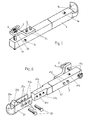
- FIG 1 we see a known reversible bar 1 whose end 1a has the shape of a hook for towing a vehicle or an agricultural machine, while at the opposite end is mounted a bent piece 2 fixed by bolts 3 which penetrate into bores 2a of part 2 and corresponding bores (not shown) of bar 1.
- a pin 4 which passes through a bore 2b of part 2 and a bore 1b of bar 1 constitutes with the part 2 and the bar 1 a towing yoke intended for the machines which must be actuated by the power take-off of a tractor.
- At about the vertical plane passing through the middle of the connection between the two portions of the part 2 and perpendicularly to the length of the bar 1 is drilled into the bar a bore 1c whose role will be ex - plicated below.
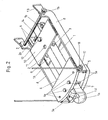
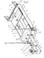
- Figures 2 and 3 show how the bar 1 can be immobilized in a known type frame for example of welded steel and constituted by two overlapping front horizontal plates 5 and 6 pierced with respective bores 5a and 6a for the passage of holding pins 7, two side pieces 8, and two rear superposed horizontal plates 9 and 10. These plates are each pierced with two bores 11 (only those of the plate 10 being visible), including the uh or the other, depending on whether the bar 1 occupies the position of FIG. 2 or that of Figure 3 is aligned vertically with the aforementioned bore 1c or with a bore 1e ( Figure 1), both drilled in the bar 1 to receive a pin 12 ( Figures 2 and 3).
- the aforementioned assembly can either be rigidly fixed under the rear axle of the tractor, in a known manner but not shown, or pivotally mounted at its rear end on the tractor by means of fixing lugs 13 and a rotation axis 14 provided at each end of retaining pins 15, while at its front end, rods 16 connect in known manner the assembly to the lifting arms (not shown) of the tractor.
- the rods 16 are pivotally mounted around axes 17 each fixed to one of the side pieces 8, and cannot be accidentally separated from these axes by means of appropriate devices 18.
- the assembly which has just been described is a "pick-up hook" intended to connect a semi-trailer to a tractor.
- the stop 1d serves as an attachment ramp for guiding the ring.
- the bar 1 is positioned for towing machines and can either oscillate freely between the plates 5 and 6, in which case the pins 7 are removed from the bores 5a, 6a, or effect a more or less limited movement between pins 7 placed in an appropriate pair of these bores.
- the bar 1 and its yoke 2 protrude forward with respect to the plates 5 and 6 so that the spindle 4 is located at the standardized distance from the PTO end piece (not shown) of the tractor.
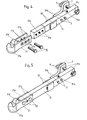
- FIG. 4 and 5 there is shown a first embodiment of a tow bar according to the invention.
- This bar is formed of two parts, 21 and 31.
- the first comprises a hook 21a identical to the hook 1a of FIG. 1, which, like it, has a stop, 21d, and which is extended towards the rear by two parallel branches 21b forming a fork whose external width is equal to the length of the sides of the square cross section of the bar 1 of FIG. 1. It is thus possible either to insert the hook 21 between the plates 5 and 6 of FIG. 2, or to "lie" between the plates 9 and 10 of Figure 3.
- Each branch of the fork 21b is pierced with two bores 21c for fixing the hook 21 to the part 31 of the bar; between the bores 21c is drilled a bore 21e intended to receive the spindle 12 when the bar 21 - 31 is inserted in the assembly 5 to 18, in the position of FIG. 3.
- the part 31 of the bar of rectangular cross section , has a front end pierced with two bores 31a capable of coming into alignment with the bores 21c of the hook 21a, and of a bore 31b capable of coming into alignment with the bore 21e to receive the spindle 12 when using the yoke formed by parts 2 and 31.
- part 21 to part 31 of the bar is carried out by rivets, elastic pins or bolts 22 which pass through the bores 21c and 31a (FIGS. 4 and 5).
- a bore 31c parallel to the bores 31a and located in the vicinity of the free end of the part 31 of the bar is intended to receive the pin 4 of the yoke.
- the part 31 of the bar is also pierced with bores 31d (FIGS. 4 and 5) through which pass the bolts 3 of the yoke.
- a bore 31e perpendicular to the bores 31a to 31d and pierced like the bore 1c in FIG. 1 roughly opposite the connection between the two parts of the part 2 is intended to receive the pin 12 when the bar 21 - 31 occupies the position of the bar 1 in FIG. 2.
- the part 31 of the bar has two plates 32 which give it a square section allowing its insertion between the plates 5 and 6 when the bar 21 - 31 occupies the position of the bar 1 in figure 3.
- FIG. 6 shows a variant of FIG. 5 in which a hook 21 is used associated with a bar 41, more rigid than the bar 31 of FIGS. 4 and 5 and of square section, which makes it possible to remove the plates 32.
- the bar 41 is pierced with bores 41a to 41e identical to the bores 31a to 31e of FIG. 4, and it has an anterior portion 41f which has been thinned down adequately so that it can be inserted between the branches 21b of the hook 21.
Landscapes
- Engineering & Computer Science (AREA)
- Transportation (AREA)
- Mechanical Engineering (AREA)
- Agricultural Machines (AREA)
Applications Claiming Priority (2)
| Application Number | Priority Date | Filing Date | Title |
|---|---|---|---|
| FR7921364A FR2463689A1 (fr) | 1979-08-24 | 1979-08-24 | Barre resersible de remorquage pour tracteurs agricoles |
| FR7921364 | 1979-08-24 |
Publications (1)
| Publication Number | Publication Date |
|---|---|
| EP0024972A1 true EP0024972A1 (fr) | 1981-03-11 |
Family
ID=9229072
Family Applications (1)
| Application Number | Title | Priority Date | Filing Date |
|---|---|---|---|
| EP80401166A Withdrawn EP0024972A1 (fr) | 1979-08-24 | 1980-08-08 | Barre réversible de remorquage pour tracteurs agricoles |
Country Status (2)
| Country | Link |
|---|---|
| EP (1) | EP0024972A1 (enExample) |
| FR (1) | FR2463689A1 (enExample) |
Cited By (2)
| Publication number | Priority date | Publication date | Assignee | Title |
|---|---|---|---|---|
| EP0277103A1 (en) * | 1987-01-16 | 1988-08-03 | Valmet Oy | Towing device for a tractor |
| CN105835845A (zh) * | 2016-04-06 | 2016-08-10 | 龙岩市海德馨汽车有限公司 | 一种带支撑装置的拖车 |
Citations (9)
| Publication number | Priority date | Publication date | Assignee | Title |
|---|---|---|---|---|
| FR1011510A (fr) * | 1949-02-23 | 1952-06-24 | Attelage automatique à décrochage de sécurité | |
| US2873981A (en) * | 1955-01-06 | 1959-02-17 | Grant Alva | General purpose extensible hitch |
| FR1176642A (fr) * | 1957-06-11 | 1959-04-14 | Cima Cie Internationale Des Ma | Barre d'attelage pour tracteurs |
| US3404901A (en) * | 1965-06-29 | 1968-10-08 | Rau Ohg Maschf | Coupling means for towing vehicles |
| GB1241083A (en) * | 1969-01-08 | 1971-07-28 | Agricultural Requisites And Me | Towing device for vehicles |
| FR2279577A1 (fr) * | 1974-05-10 | 1976-02-20 | Walterscheid Gmbh Jean | Barre porte-crochet superieur de longueur variable |
| FR2298449A1 (fr) * | 1975-01-27 | 1976-08-20 | Bertholomey Georges | Dispositifs de perfectionnements de securite aux attelages/remorques en mixte emplois, inter-trac |
| FR2368210A1 (fr) * | 1976-10-20 | 1978-05-19 | Daimler Benz Ag | Dispositif d'attelage pour tracteur agricole |
| FR2408476A1 (fr) * | 1977-11-10 | 1979-06-08 | Deere & Co | Adaptateur pour systemes d'attelage |
-
1979
- 1979-08-24 FR FR7921364A patent/FR2463689A1/fr active Granted
-
1980
- 1980-08-08 EP EP80401166A patent/EP0024972A1/fr not_active Withdrawn
Patent Citations (9)
| Publication number | Priority date | Publication date | Assignee | Title |
|---|---|---|---|---|
| FR1011510A (fr) * | 1949-02-23 | 1952-06-24 | Attelage automatique à décrochage de sécurité | |
| US2873981A (en) * | 1955-01-06 | 1959-02-17 | Grant Alva | General purpose extensible hitch |
| FR1176642A (fr) * | 1957-06-11 | 1959-04-14 | Cima Cie Internationale Des Ma | Barre d'attelage pour tracteurs |
| US3404901A (en) * | 1965-06-29 | 1968-10-08 | Rau Ohg Maschf | Coupling means for towing vehicles |
| GB1241083A (en) * | 1969-01-08 | 1971-07-28 | Agricultural Requisites And Me | Towing device for vehicles |
| FR2279577A1 (fr) * | 1974-05-10 | 1976-02-20 | Walterscheid Gmbh Jean | Barre porte-crochet superieur de longueur variable |
| FR2298449A1 (fr) * | 1975-01-27 | 1976-08-20 | Bertholomey Georges | Dispositifs de perfectionnements de securite aux attelages/remorques en mixte emplois, inter-trac |
| FR2368210A1 (fr) * | 1976-10-20 | 1978-05-19 | Daimler Benz Ag | Dispositif d'attelage pour tracteur agricole |
| FR2408476A1 (fr) * | 1977-11-10 | 1979-06-08 | Deere & Co | Adaptateur pour systemes d'attelage |
Cited By (2)
| Publication number | Priority date | Publication date | Assignee | Title |
|---|---|---|---|---|
| EP0277103A1 (en) * | 1987-01-16 | 1988-08-03 | Valmet Oy | Towing device for a tractor |
| CN105835845A (zh) * | 2016-04-06 | 2016-08-10 | 龙岩市海德馨汽车有限公司 | 一种带支撑装置的拖车 |
Also Published As
| Publication number | Publication date |
|---|---|
| FR2463689B1 (enExample) | 1982-12-31 |
| FR2463689A1 (fr) | 1981-02-27 |
Similar Documents
| Publication | Publication Date | Title |
|---|---|---|
| EP0654205B1 (fr) | Machine agricole à timon perfectionné | |
| FR2677212A1 (fr) | Entretoise laterale telescopique pour une barre inferieure d'un attelage trois points. | |
| EP1227945A1 (fr) | Dispositif d'attelage pour chariot de manutention | |
| EP0403409B1 (fr) | Machine agricole pour l'andainage comportant des bras porte-outils repliables | |
| EP0024972A1 (fr) | Barre réversible de remorquage pour tracteurs agricoles | |
| EP1051894A1 (fr) | Dispositif d'adaptation pour barre d'attelage de tracteur | |
| FR2539576A1 (fr) | Dispositif d'accouplement, notamment entre la prise de force d'un tracteur et un outil agricole relie a ce tracteur | |
| EP2786648B1 (fr) | Dispositif d'attelage perfectionné | |
| EP0807541B1 (fr) | Ensemble de manutention à chariots et timons | |
| FR2769171A1 (fr) | Attelage d'outil pour vehicule, notamment pour tracteur agricole | |
| WO2003075635A2 (fr) | Machine agricole destinee a etre attelee a une barre d'attelage d'un vehicule tracteur | |
| FR2876957A1 (fr) | Timon d'attelage pour chariot de manutention et dispositif d'attelage l'incorporant | |
| EP0426588A1 (fr) | Perfectionnement aux machines agricoles destinées notamment à la fenaison | |
| FR2646052A1 (fr) | Dispositif pour la traction simultanee d'au moins deux outils aratoires par un meme tracteur | |
| EP4098498B1 (fr) | Dispositif d'accrochage d'une remorque à un véhicule tracteur pourvu d'une structure de liaison articulé | |
| FR2697129A1 (fr) | Dispositif de raccordement pour le timon d'un élément tracté. | |
| FR2677927A1 (fr) | Dispositif pour atteler une remorque ou un appareil a un tracteur. | |
| FR2575027A1 (fr) | Dispositif d'attelage pour chargeur frontal de tracteur | |
| FR2729816A1 (fr) | Dispositif d'attelage pour tracteur agricole | |
| EP4282237A1 (fr) | Dispositif de liaison perfectionne pour relier un instrument agricole a un attelage trois points | |
| FR1465530A (fr) | Dispositif d'attelage, notamment pour l'attelage en trois points d'instruments aratoires à des tracteurs | |
| EP0256951B1 (fr) | Dispositif de fixation de barres oscillantes réversibles dans un attelage à fourreau mobile | |
| FR2559714A3 (fr) | Structure d'attelage d'un vehicule tracteur a une remorque et remorque pourvue de cette structure | |
| FR3135765A1 (fr) | Dispositif d’accouplement | |
| EP1256268B1 (fr) | Dispositif d'attelage d'un semoir à une machine de travail du sol, à biellettes de fixation |
Legal Events
| Date | Code | Title | Description |
|---|---|---|---|
| PUAI | Public reference made under article 153(3) epc to a published international application that has entered the european phase |
Free format text: ORIGINAL CODE: 0009012 |
|
| AK | Designated contracting states |
Designated state(s): DE GB IT SE |
|
| 17P | Request for examination filed |
Effective date: 19810326 |
|
| STAA | Information on the status of an ep patent application or granted ep patent |
Free format text: STATUS: THE APPLICATION IS DEEMED TO BE WITHDRAWN |
|
| 18D | Application deemed to be withdrawn |
Effective date: 19831102 |
|
| RIN1 | Information on inventor provided before grant (corrected) |
Inventor name: MARTINOT, ROGER Inventor name: CANON, HERVE Inventor name: DIENNE, DIDIER Inventor name: MIJOT, GUY |