EP0024809B1 - Apparat für Querstromkontaktierung von einem Fluid mit Feststoffteilchen in einem magnetisch stabilisierten Bett dieser Feststoffteilchen und Verfahren zu dessen Verwendung - Google Patents
Apparat für Querstromkontaktierung von einem Fluid mit Feststoffteilchen in einem magnetisch stabilisierten Bett dieser Feststoffteilchen und Verfahren zu dessen Verwendung Download PDFInfo
- Publication number
- EP0024809B1 EP0024809B1 EP80302494A EP80302494A EP0024809B1 EP 0024809 B1 EP0024809 B1 EP 0024809B1 EP 80302494 A EP80302494 A EP 80302494A EP 80302494 A EP80302494 A EP 80302494A EP 0024809 B1 EP0024809 B1 EP 0024809B1
- Authority
- EP
- European Patent Office
- Prior art keywords
- particles
- bed
- chamber
- gas
- solids
- Prior art date
- Legal status (The legal status is an assumption and is not a legal conclusion. Google has not performed a legal analysis and makes no representation as to the accuracy of the status listed.)
- Expired
Links
Images


Classifications
-
- B—PERFORMING OPERATIONS; TRANSPORTING
- B01—PHYSICAL OR CHEMICAL PROCESSES OR APPARATUS IN GENERAL
- B01J—CHEMICAL OR PHYSICAL PROCESSES, e.g. CATALYSIS OR COLLOID CHEMISTRY; THEIR RELEVANT APPARATUS
- B01J8/00—Chemical or physical processes in general, conducted in the presence of fluids and solid particles; Apparatus for such processes
- B01J8/18—Chemical or physical processes in general, conducted in the presence of fluids and solid particles; Apparatus for such processes with fluidised particles
- B01J8/24—Chemical or physical processes in general, conducted in the presence of fluids and solid particles; Apparatus for such processes with fluidised particles according to "fluidised-bed" technique
- B01J8/42—Chemical or physical processes in general, conducted in the presence of fluids and solid particles; Apparatus for such processes with fluidised particles according to "fluidised-bed" technique with fluidised bed subjected to electric current or to radiations this sub-group includes the fluidised bed subjected to electric or magnetic fields
-
- B—PERFORMING OPERATIONS; TRANSPORTING
- B01—PHYSICAL OR CHEMICAL PROCESSES OR APPARATUS IN GENERAL
- B01D—SEPARATION
- B01D46/00—Filters or filtering processes specially modified for separating dispersed particles from gases or vapours
- B01D46/30—Particle separators, e.g. dust precipitators, using loose filtering material
- B01D46/32—Particle separators, e.g. dust precipitators, using loose filtering material the material moving during filtering
-
- B—PERFORMING OPERATIONS; TRANSPORTING
- B01—PHYSICAL OR CHEMICAL PROCESSES OR APPARATUS IN GENERAL
- B01D—SEPARATION
- B01D53/00—Separation of gases or vapours; Recovering vapours of volatile solvents from gases; Chemical or biological purification of waste gases, e.g. engine exhaust gases, smoke, fumes, flue gases, aerosols
- B01D53/02—Separation of gases or vapours; Recovering vapours of volatile solvents from gases; Chemical or biological purification of waste gases, e.g. engine exhaust gases, smoke, fumes, flue gases, aerosols by adsorption, e.g. preparative gas chromatography
- B01D53/06—Separation of gases or vapours; Recovering vapours of volatile solvents from gases; Chemical or biological purification of waste gases, e.g. engine exhaust gases, smoke, fumes, flue gases, aerosols by adsorption, e.g. preparative gas chromatography with moving adsorbents, e.g. rotating beds
- B01D53/08—Separation of gases or vapours; Recovering vapours of volatile solvents from gases; Chemical or biological purification of waste gases, e.g. engine exhaust gases, smoke, fumes, flue gases, aerosols by adsorption, e.g. preparative gas chromatography with moving adsorbents, e.g. rotating beds according to the "moving bed" method
-
- B—PERFORMING OPERATIONS; TRANSPORTING
- B01—PHYSICAL OR CHEMICAL PROCESSES OR APPARATUS IN GENERAL
- B01D—SEPARATION
- B01D53/00—Separation of gases or vapours; Recovering vapours of volatile solvents from gases; Chemical or biological purification of waste gases, e.g. engine exhaust gases, smoke, fumes, flue gases, aerosols
- B01D53/34—Chemical or biological purification of waste gases
- B01D53/46—Removing components of defined structure
- B01D53/48—Sulfur compounds
-
- B—PERFORMING OPERATIONS; TRANSPORTING
- B01—PHYSICAL OR CHEMICAL PROCESSES OR APPARATUS IN GENERAL
- B01F—MIXING, e.g. DISSOLVING, EMULSIFYING OR DISPERSING
- B01F33/00—Other mixers; Mixing plants; Combinations of mixers
- B01F33/45—Magnetic mixers; Mixers with magnetically driven stirrers
- B01F33/451—Magnetic mixers; Mixers with magnetically driven stirrers wherein the mixture is directly exposed to an electromagnetic field without use of a stirrer, e.g. for material comprising ferromagnetic particles or for molten metal
-
- B—PERFORMING OPERATIONS; TRANSPORTING
- B01—PHYSICAL OR CHEMICAL PROCESSES OR APPARATUS IN GENERAL
- B01J—CHEMICAL OR PHYSICAL PROCESSES, e.g. CATALYSIS OR COLLOID CHEMISTRY; THEIR RELEVANT APPARATUS
- B01J8/00—Chemical or physical processes in general, conducted in the presence of fluids and solid particles; Apparatus for such processes
- B01J8/08—Chemical or physical processes in general, conducted in the presence of fluids and solid particles; Apparatus for such processes with moving particles
- B01J8/12—Chemical or physical processes in general, conducted in the presence of fluids and solid particles; Apparatus for such processes with moving particles moved by gravity in a downward flow
-
- B—PERFORMING OPERATIONS; TRANSPORTING
- B01—PHYSICAL OR CHEMICAL PROCESSES OR APPARATUS IN GENERAL
- B01D—SEPARATION
- B01D2251/00—Reactants
- B01D2251/40—Alkaline earth metal or magnesium compounds
- B01D2251/404—Alkaline earth metal or magnesium compounds of calcium
-
- B—PERFORMING OPERATIONS; TRANSPORTING
- B01—PHYSICAL OR CHEMICAL PROCESSES OR APPARATUS IN GENERAL
- B01D—SEPARATION
- B01D2251/00—Reactants
- B01D2251/60—Inorganic bases or salts
- B01D2251/602—Oxides
-
- B—PERFORMING OPERATIONS; TRANSPORTING
- B01—PHYSICAL OR CHEMICAL PROCESSES OR APPARATUS IN GENERAL
- B01D—SEPARATION
- B01D2253/00—Adsorbents used in seperation treatment of gases and vapours
- B01D2253/10—Inorganic adsorbents
- B01D2253/104—Alumina
-
- B—PERFORMING OPERATIONS; TRANSPORTING
- B01—PHYSICAL OR CHEMICAL PROCESSES OR APPARATUS IN GENERAL
- B01D—SEPARATION
- B01D2253/00—Adsorbents used in seperation treatment of gases and vapours
- B01D2253/10—Inorganic adsorbents
- B01D2253/112—Metals or metal compounds not provided for in B01D2253/104 or B01D2253/106
- B01D2253/1124—Metal oxides
-
- B—PERFORMING OPERATIONS; TRANSPORTING
- B01—PHYSICAL OR CHEMICAL PROCESSES OR APPARATUS IN GENERAL
- B01D—SEPARATION
- B01D2253/00—Adsorbents used in seperation treatment of gases and vapours
- B01D2253/25—Coated, impregnated or composite adsorbents
-
- B—PERFORMING OPERATIONS; TRANSPORTING
- B01—PHYSICAL OR CHEMICAL PROCESSES OR APPARATUS IN GENERAL
- B01D—SEPARATION
- B01D2253/00—Adsorbents used in seperation treatment of gases and vapours
- B01D2253/30—Physical properties of adsorbents
- B01D2253/302—Dimensions
- B01D2253/304—Linear dimensions, e.g. particle shape, diameter
-
- B—PERFORMING OPERATIONS; TRANSPORTING
- B01—PHYSICAL OR CHEMICAL PROCESSES OR APPARATUS IN GENERAL
- B01D—SEPARATION
- B01D2253/00—Adsorbents used in seperation treatment of gases and vapours
- B01D2253/30—Physical properties of adsorbents
- B01D2253/302—Dimensions
- B01D2253/306—Surface area, e.g. BET-specific surface
-
- B—PERFORMING OPERATIONS; TRANSPORTING
- B01—PHYSICAL OR CHEMICAL PROCESSES OR APPARATUS IN GENERAL
- B01D—SEPARATION
- B01D2257/00—Components to be removed
- B01D2257/30—Sulfur compounds
- B01D2257/302—Sulfur oxides
-
- B—PERFORMING OPERATIONS; TRANSPORTING
- B01—PHYSICAL OR CHEMICAL PROCESSES OR APPARATUS IN GENERAL
- B01D—SEPARATION
- B01D2257/00—Components to be removed
- B01D2257/40—Nitrogen compounds
- B01D2257/404—Nitrogen oxides other than dinitrogen oxide
-
- B—PERFORMING OPERATIONS; TRANSPORTING
- B01—PHYSICAL OR CHEMICAL PROCESSES OR APPARATUS IN GENERAL
- B01D—SEPARATION
- B01D2258/00—Sources of waste gases
- B01D2258/02—Other waste gases
- B01D2258/0283—Flue gases
-
- B—PERFORMING OPERATIONS; TRANSPORTING
- B01—PHYSICAL OR CHEMICAL PROCESSES OR APPARATUS IN GENERAL
- B01D—SEPARATION
- B01D2259/00—Type of treatment
- B01D2259/40—Further details for adsorption processes and devices
- B01D2259/40011—Methods relating to the process cycle in pressure or temperature swing adsorption
- B01D2259/40077—Direction of flow
- B01D2259/40081—Counter-current
-
- B—PERFORMING OPERATIONS; TRANSPORTING
- B01—PHYSICAL OR CHEMICAL PROCESSES OR APPARATUS IN GENERAL
- B01D—SEPARATION
- B01D2259/00—Type of treatment
- B01D2259/40—Further details for adsorption processes and devices
- B01D2259/40083—Regeneration of adsorbents in processes other than pressure or temperature swing adsorption
- B01D2259/40088—Regeneration of adsorbents in processes other than pressure or temperature swing adsorption by heating
- B01D2259/4009—Regeneration of adsorbents in processes other than pressure or temperature swing adsorption by heating using hot gas
Definitions
- the present invention relates to apparatus for cross-flow contacting of a fluid with particulate solids in a magnetically stabilized fluidized bed of said solids, and processes using same, and more particularly to a fluid cross-flow fluid-solid contactor of the panel or radial reactor type wherein ferromagnetic bed solids are structured or stabilized by the action of a magnetic field, and processes using the contractor, and is particularly concerned with means for contacting fluids and solid particles in one or more such cross-flow beds, having an imposed magnetic field.
- the invention also relates to a method for removing particulates from a gas containing the same and flue gas desulfurization processes utilizing a cross-flow or panel bed contactor stabilized by the action of a magnetic field.
- Conditions at the minimum fluid flow required to produce the fluid-like, or fluidized conditions i.e., the incipient fluidization point, are dependent on many parameters including particle size, particle density, etc.
- the increase in the fluid flow beyond the incipient fluidization point causes an expansion of the fluidized bed to accommodate the increased fluid flow until the fluid velocity exceeds the free falling velocity of the particles which are then carried out of the apparatus, a condition known as entrainment.
- cross-flow and colinear EFB's by the term cross-flow EFB's, they actually describe contactors wherein the gas flow levitates the fluidizable particles as in the typical axial flow contactor.
- a cross-flow gas contactor is understood to be a contactor wherein the gas flows perpendicular to the external force field, i.e., gravity.
- the EFB's described by Melcher et al. have been shown to be useful collecting particulates, especially submicron particulates.
- the EFB's having a vertical gas flow are unable to process gas streams at velocities greater than 1 ft./sec. without encountering substantial pressure drops and/or entrainment of solids, e.g., using sand particles.
- Cross-flow and panel bed fluid-solid contactors i.e., where the fluid (gas) flow is perpendicular to gravity
- the first industrial use being known as the Deacon process developed nearly 100 years ago.
- Perry's Chemical Engineers' Handbook, 5th Edition discloses details of several fluid cross-flow contactors of the type described by Dorfan, Squires and Zenz.
- Such processes eliminate the need for a porous grid such as is required in fluidized beds of Rosenweig and Melcher et al. As reported by Squires and Pfeffer (J. of the Air Pollution Control Association, Vol. 20, No. 8, pp.
- 3,296,775 to Squires discloses that filter cake and a controlled amount of filter solid can be removed from each gas-entry surface by applying a surge backflow of gas from the clean side of the panel.
- Various improvements have been described in U.S. Patent Nos. 3,410,055; 4,006,533; 4,004,896; 3,982,326; 4,004,350; 3,926,587; 3,926,593; 3,957,953, 3,981,355; 3,987,148; and 4,000,066.
- U.S. Patent Nos. 4,102,982 to Weir, Jr.; 4,017,278 and 4,126,435 to Reese also disclose processes for removing finely divided solids from gaseous streams by use of gas cross-flow contactors.
- the Reese patent discloses the use of louvered surfaces formed by perforating the walls to form louver vanes inclined to the vertical at angles ranging from 15° to 80°.
- U.S. Patent No. 3,966,879 to Groenendaal et al. discloses a process for the removal of particulate matter and sulfur oxides from waste gases which comprises cross-current contacting of the waste gas stream with a moving bed of supported, copper-containing acceptor.
- relatively high superficial gas velocities i.e., the order of 2-8 ft./sec. (60-245 cm./sec.) and higher with particles having a mean diameter size about 0.03 to 0.1 cms (300-1000 microns) are desired.
- the high velocities are desired so as to keep equipment of a practical size, despite the large volumes of gas to be processed and the small particle sizes facilitate intimate contacting of all of the gas with bed solids and effective use of all of the bed solids.
- Contactors capable of such high velocities with relatively small particles and at low pressure drops have hitherto not been described.
- a fluid preferably a gas
- a fluid cross-flow contactor wherein the solids are structured or stabilized by the action of a magnetic field, said particles being ferromagnetic or made ferromagnetic by the inclusion within the particle material having this property wherein the magnetic field is transverse to the flow of fluid through the bed of solid particles and substantially colinear with the external force field, i.e., gravity.
- a magnetically stabilized fluid cross-flow bed comprising:
- the apparatus preferably includes a plenum means communicating with said opening means on said chamber for introducing and withdrawing fluid (e.g., gas) to and from said chamber.
- fluid e.g., gas
- the chamber preferably comprises one or more upwardly extending horizontally or alternatively concentric spaced-apart perforate retaining means wherein the retaining means are in communication with the respective gas inlet and gas outlet plenum.
- Still another embodiment of the invention pertains to a process for removing particulates from gaseous streams, such streams exist in nitrogen oxide removal and flue gas desulfurization processes and in combined cycle power processes as hereinafter described.
- the process of the invention utilizing the magnetically stabilized cross-flow bed contactor permits gas solids contacting at relatively high superficial gas velocities, e.g., gas velocities at the face of the contacting chamber ranging from 15.24 cms/sec (0.5 ft./sec.) up to 304.8 cms/sec (10 ft./sec.) and more, utilizing particles having a mean diameter of 0.15 cms (1500 microns) or less and preferably less than 0.1 cms (1000 microns).
- relatively high superficial gas velocities e.g., gas velocities at the face of the contacting chamber ranging from 15.24 cms/sec (0.5 ft./sec.) up to 304.8 cms/sec (10 ft./sec.) and more, utilizing particles having a mean diameter of 0.15 cms (1500 microns) or less and preferably less than 0.1 cms (1000 microns).
- the higher voidages also permit superficial gas velocities up to 4 times or more than similar beds not stabilized by the magnetic field at comparable pressure drops.
- the magnetically stabilized cross-flow beds of the present invention can possess 5 times or more bed particles per unit volume of bed compared to comparable fixed beds or moving beds because of the relatively smaller particle size which can be used.
- the contactor can contain a larger external surface area of particles per unit volume of bed compared to a normal bed of the same pressure drop.
- the present invention relates to a magnetically stabilized cross-flow gas-solids contacting apparatus which includes:
- the chamber may be e.g. rectangular or annular.
- the chamber may comprise one or more pairs of substantially upwardly extending horizontally spaced-apart perforate retaining walls, one of which is in communication with the gas inlet plenum and the other of which is in communication with the gas outlet plenum.
- the openings on the chamber will preferably include a plurality of support members, each of which are adjacent to the openings and in communication with the gas inlet plenum.
- the support members are arranged to extend outwardly from below their adjacent openings and into the inlet plenum to support and expose to the chamber a plurality of free surfaces of particulate material. They are arranged cooperatively to support the solid, discrete magnetizable particles and retain the particles within the contacting chamber.
- a similar arrangement of outwardly extending support members, each of which is adjacent to the openings and in communication with the gas outlet plenum, will be positioned opposite the inlet plenum.
- Both of these outward extending support members are preferably inclined at an upward angle to enable higher gas velocities to be employed without blow-out of the solids.
- the angle of upward and outward incline will vary, depending on the gas velocity, size and shape of the particles, and the magnetization of the particles (as induced by the applied magnetic field), and is preferably greater than 45°.
- the support members or louvers may be of special design to facilitate air flow into and out of the chamber as well as provide support for the magnetizable particles.
- the louvres or support members may be arranged to extend outwardly and downwardly in a general curve from below their adjacent opening and then extend further in a general curve upwardly and into the chamber.
- the edge of such support may be either above the inner edge of the free surface supported by the member or, when below, a line drawn through these edges is inclined at an angle of less than about 60° to the horizontal, preferably less than 45° to the horizontal.
- Another form of the louvres or support members may have a first portion which extends upward (preferably at an angle greater than 45° to the horizontal) and outward from the openings toward the incoming fluid, and a second portion which extends outward and downward (preferably at an angle greater than 45° to the horizontal) away from the chamber, so as to form a A-configuration.
- the chamber most suitably comprises a plurality of perforate panels joined end-to-end to one another and folded back so as to be arranged like the pleats of an accordian as shown in the cross-sectional top view in Fig. 6.
- This arrangement provides maximum contacting volume per unit of space required for efficient contacting and also maximizes use of the electromagnetic coils surrounding the chamber.
- the thickness of the contacting chamber is preferably kept as small as possible to minimize the pressure drop of gas passing through the bed.
- the thickness will be a function of the needed contact time and allowable pressure drop.
- the thickness of the chamber retaining the solid, discrete magnetizable, fluidizable particles will be in the range from about 2.54 cms (1 inch) to about 60.1 cms (2 feet), preferably from about 5.08 cms to 30.48 cms) (2 to about 12 inches) and, more preferably, from about 10.16 to 25.4 cms (4-10 inches) thick.
- the height of the contacting chamber may vary substantially depending on space available, volume of gas to be processed, etc.
- the height may range from 30.48 cms (1 ft.) up to as high as 24.4 metres or 30.5 metres (80 or 100 ft).
- a commercial unit may typically be 3.05 to 18.30 m (10 to 60 ft.), or 7.62 to 15.24 m (25 to 50 ft.) high.
- the perforate chamber walls it is preferred to provide a seal zone above and below the openings in the chamber, i.e., zones where no openings exist as shown in Fig. 4.
- the seal zones prevent the gas from leaking upward or downward within the chamber containing magnetizable solid particles.
- the magnet means for magnetizing the solid, discrete magnetizable particles within the chamber is generated by a plurality of solenoid or electromagnetic coils which surround the contacting chamber.
- the coils are preferably arranged in such a manner that they establish a magnetic field substantially colinear with the external force field (e.g., gravity) and substantially perpendicular to the flow of gas through the bed of magnetized solid particles.
- the magnetic field is preferably established by two or more electromagnet coils of circular or semi-rectangular toroidal form positioned around the outer wall of the apparatus.
- the magnetic field is preferably substantially uniformly applied to at least a portion or a zone of the chamber containing the solid, discrete magnetizable particles.
- the magnetic field is imposed on at least the region or regions where the openings in the vessel exist and most preferably the entire chamber.
- the region stabilized by the applied field has a variation of its vertical magnetic component less than 25% of the average vertical component over the region or zone of the chamber containing the solid, discrete magnetizable particles. More preferably, the magnetic field intensity will vary no more than 10% and more preferably no more than 5% over the stabilized region. Often, it will be deemed desirable to design such regions or zones to have only about a 5% or less variance.
- the entire chamber(s) be stabilized by the magnetic field.
- the entire bed of solids can be controlled.
- the variation of the vertical component of the magnetic field to the mean field in the bed should be no greater than 10%.
- such chambers will be designed to have less than 5% variation over the mean.
- Such uniform fields have the greatest tendency to form a homogeneous, yet anisotropic, bed.
- the electromagnet coil may be energized by direct current (DC) or alternating current (AC); however, DC, i.e., nontime varying, vertical fields are preferred since they are able to provide a uniform field with the lowest power requirements. If desired for special purposes, one may employ a spatially uniform DC field having a superposed AC component. Such an arrangement will behave substantially like a DC field if the DC field intensity is substantially greater than the amplitude of the AC field intensity.
- the intensity of the required magnetic field will vary greatly, depending on the magnetization properties of the solid, discrete, magnetizable particles, the degree of magnetization of the particles desired, i.e., how fluid, stiff or locked, one wishes the particles.
- the applied magnetic field will generally range from about 25 to about 1000 oersteds (2.5 x 10- 4 to 1.0 x 10- 1 Tesla), preferably from 50 to about 500 oersteds, and more preferably from 100 to about 300 oersteds.
- the solid, discrete, magnetizable particles to be used in the practice of the invention are preferably particles having a low or zero coercivity to facilitate solids handling external to the magnetized contacting chamber.
- Ferromagnetic and ferrimagnetic substances including but not limited to magnetic Fe 3 0 4 , y-iron oxide (Fe z 0 3 ) ferrites of the form XO.Fe 2 o 3 , wherein X is a metal or mixture of metals such as Zn, Mn, Cu, etc.; ferromagnetic elements including iron, nickel, cobalt, and gadolinium, alloys of ferromagnetic elements, etc., may be used as the magnetizable solid particles.
- Nonmagnetic materials may be coated with and/or contain dispersed therein solids having the quality of ferromagnetism.
- composites of magnetizable solid particles prepared for use in some catalytic processes may contain from 2 to 40 volume percent and preferably 5 to 20 volume percent and more preferably 10 to 15 volume percent of the ferro- or ferrimagnetic material and the balance will be comprised of nonmagnetic material.
- the bed solids in the chamber containing the magnetizable particles may also include particulate solids which are nonmagnetizable. In other processes, for example, where high magnetization is desired, it will be desirable to use 100% ferro- or ferrimagnetic solids.
- the solid, discrete, magnetizable particles are most preferably composite magnetizable particles.
- Such particles may each be a composite of magnetizable material and non-magnetizable material.
- the particles may be characterized as being elongated.
- Such magnetizable compositions are comprised of geometrically elongated particles constituted of composites of nonferromagnetic solids and elongate ferromagnetic inclusions, particularly compositions wherein the inclusions are parallely aligned in the direction of the major axis of the particle.
- These particles preferably have high L/D ratio, i.e., at least 2: 1, and preferably 4:1 and more preferably 10:1 and more.
- These elongated particles have demagnetization coefficients significantly less than 1/3.
- the magnetizable composites may be prepared by parallelly aligning and orienting elongate ferromagnetic inclusions in an admixture of a hydrogel precursor and said elongate inclusions prior to gelation, and maintaining such alignment or orientation of the ferromagnetic particles during gelation which takes place in a hot oil bath.
- Another composite comprises: (i) particulate admixtures of nonferromagnetic solids and elongate ferromagnetic solids; (ii) composites comprising particulates constituted of nonferromagnetic solids and a single elongate ferromagnetic inclusion; (iii) composites comprising particulates constituted of nonferromagnetic solids and a plurality of elongate ferromagnetic inclusions wherein the long sides of the inclusions are parallely aligned and (iv) processes of using any of (i), (ii), or (iii) for fluids-solids contacting. Still another composite comprises particles constituted of nonferromagnetic solids and a plurality of elongate ferromagnetic inclusions randomly aligned as well as processed for using the compositions for fluid-solids contacting.
- materials having a high Curie point be employed.
- materials having a high Curie point are disclosed in DE-A-2950621 to R. C. Krutenat and Chih-an Liu.
- a base magnetic metal such as iron or cobalt is alloyed with aluminum, chromium, silicon or combinations of these materials (and optionally, Y, Hf, Zr or La can be incorporated) and air oxidized at elevated temperatures.
- the size of the solid, discrete magnetizable particles will be such that their mean diameter ranges from about 0.01 to 0.15 cms (100 to about 1500 microns), preferably from 0.015 to 0.10 cms (150 to about 1000 microns) and more preferably from about 0.025 to 0.050 cms (250 to about 500 microns).
- the particle size range referred to herein is that determined by the mesh openings of a first sieve through which particles pass and a second sieve on which the particles are retained.
- the solid, discrete magnetizable fluidizable particles may be admixed with nonmagnetic materials.
- nonmagnetic materials for example, silica, alumina, metals, e.g., copper and salts thereof, catalysts, coal, etc.
- the volume fraction of magnetizable particles exceed 75 percent, or preferably exceed 90 volume percent of the total particles.
- the bed will be composed of 100 volume percent of the magnetizable particles (i.e., it will not contain admixtures of other materials).
- the nonmagnetizable admixtures exceed 25 volume percent, the particle mixtures may separate analogous to liquids of limited solubility.
- the magnetization M of the particle An important factor in selecting or preparing the solid magnetizable particles is the magnetization M of the particle.
- the magnetization M of the solid, discrete magnetizable particles in the bed within the contacting chamber may be within the range of from 10 to 500 gauss. M may be at least 10 gauss.
- the particles will have a magnetization, as being imparted by the applied magnetic field, of at least 50 gauss, preferably at least 100 gauss and more preferably at least about 150 gauss, e.g., 150-400 gauss.
- the magnetization of the particles may be up to about 1000 gauss or more. In some instances it will be desired to create a degree of magnetization on the particles such that they form a stiff mass or lock-up within the contactor vessel, rather than allow the particles to flow in a downward motion by the action of gravity.
- one aspect of the instant invention pertains to controlling the rate of descent of the particles simply by the application of the applied magnetic field.
- the applied magnetic field can control the rate of flow of the particles, the voidages in the bed, the gas velocities at which the system one can operate and the relative efficiency of the gas-solids contacting process.
- the magnetization, M, of the particles, as is well-known, is defined as B-H in the particle, where B is the magnetic induction and H is the magnetic field, the fields being defined in standard published works in electromagnetism, e.g., Electromagnetic Theory, J. A. Stratton, McGraw-Hill (1941). ).
- the value of M may be measured in a variety of ways, all of which can give the same value M since M has an objective reality.
- One means for determining magnetization M of the particles in a bed under the influence of a given applied magnetic-field is to measure their magnetic moment at that field in a vibrating sample magnetometer under conditions of similar voidage, sample geometry and temperatures as exist in the process to be used.
- the magnetometer gives a value of a, the magnetic moment per gram from which magnetization M is obtained from the formula: where p is the density of the particles in the test samples, a is the magnetic moment in emu/gm (electromagnetic units per gram), M is the magnetization of the particles in gauss at the applied magnetic field used in the test and 7 r is 3.1416 ... a well-known physical constant.
- the actual magnetization of the particles in the contacting chamber will be a function of the particles themselves (i.e., the degree of magnetizability they inherently possess) and the intensity of the applied magnetic field. It is to be understood that the term "applied magnetic field" used throughout the specification and claims refers to an empty chamber or vessel applied magnetic field.
- the magnetizable particles should have a certain degree of magnetization M which is imparted to the particles by the intensity of the applied magnetic field. Obviously one would seek the lowest applied magnetic field possible because of cost. Commonly, many of the composite particles referred to in the above-mentioned patent applications will require at least 50 oersteds, more often more than 100 and preferably less than 1000 oersteds applied magnetic field to achieve the requisite magnetization M. The determination of the applied magnetic field will take into account the type of particles employed, i.e., their magnetization, particles size and distribution, the superficial fluid velocity to be used, etc.
- the magnetization M of a particle as obtained from a magnetometer when a given magnetizing field H a is applied will not provide a value which is the same as the magnetization of the particle in response to the same intensity of magnetic field in the contacting chamber to be used in accordance with the teachings of the present invention.
- the purpose of the following is to indicate a method for determining the magnetization Mp of a typical particle in a bed from those values obtained from a magnometometer. Generally, this will require a calculation since the effective field that a bed particle is subjected to depends on the applied field, the bed geometry, the particle geometry, the bed voidage and particle magnetization. A general expression has been derived to relate these quantities based on the classical approximation of the Lorentz cavity that is employed in analogous physical problems such as the polarization of dielectric molecules.
- H a is the applied magnetic field as measured in the absence of the particles, He the magnetic field within a particle, Mp the particle magnetization, dp the particle demagnetization coefficient, ⁇ o the voidage in the bed, and d b the bed demagnetization coefficient.
- the term -1/3 is due to the magnetizing influence of a (virtual) sphere surrounding the bed particle.
- d b is the demagnetization coefficient d s corresponding to shape of the cavity in the sample holder.
- Magnetometer measurement produces a graph of Mp vs. H a .
- dp, d s , ⁇ o , Mp and H a a corresponding value of He may be computed.
- H e its value found in this manner is determined by a difference between large numbers, hence is subject to cumulative errors. Accordingly, a modified approach is useful as described in the following.
- H s representing the calculated field in a spherical cavity at the location of the particle. It is imagined that the magnetization of surrounding particles is unchanged when the said particle is removed. Combining the two expressions gives an alternate relationship for H S , in which H a is eliminated. The expression is recognized to give H s as the change of field in passing from the inside of a particle to the outside of the particle.
- K m the quantity M p /(H a - H s ) i.e.,
- Mp the quantity of Mp and H s .
- d s 1/3
- K m the quantity of K m intersecting the measured curve and the H a axis
- H s H a
- a constant Kp may be defined as follows:
- Eq. (1) is an approximation which is more accurate for beds having high voidage than for very densely packed samples.
- the superficial fluid velocity employed in operating the magnetically stabilized cross-flow contactor may be regulated to vary over a wide range of superficial fluid velocities. However, the superficial fluid velocity should be insufficient to cause substantial entrainment of the smaller bed particles in the exit gas stream or insufficient to cause "solids blow-out.” Solids blow-out occurs at a relatively low superficial fluid velocity in unstabilized cross-flow contactors.
- the application of the magnetic field, in the case of the magnetically stabilized cross-flow contactor enables one to use substantially higher superficial fluid velocities before substantial solids entrainment or solids blow-out.
- the superficial fluid velocity sufficient to cause substantial entrainment of the smaller bed particles in the exit gas stream may be insufficient to cause "solids blow-out".
- the superficial fluid velocity sufficient to cause solids blow-out is the superficial fluid velocity at which the solids suddenly (catastrophically) exit through the gas exit openings of the contactor. This occurs when the aerodynamic drag on the bed by the gas flow exceeds the retaining forces which derive from the particle-to-particle coupling due to the magnetic field and from the physical barrier provided by the gas exit openings' inner surfaces.
- the magnetization of the particles in the bed and the size of the gas exit openings are interrelated in determining the maximum superficial fluid velocity that can be tolerated before solids blow-out occurs.
- the blow-out superficial fluid velocity in the case of the instant magnetically stabilized cross-flow contactor can be controlled by appropriate magnetization of the particles (e.g., by increasing the applied magnetic field).
- blow-out velocity may be represented in the following terms at blow-out:
- the superficial fluid velocity at the face of the contactor may be as high as 10 ft./sec. (i.e., 300 cm./sec.).
- the superficial fluid velocity at which blow-out will occur will be up to 183 cm/s (6 ft./sec.) and more often 45.7 to 137.2 cm/s (1.5 ft./sec. to 4.5 ft./sec.)
- the pressure drops encountered by operating the contactor of the invention is generally quite low. It will generally be less than 2-3 cms/cm of bed, more preferably less than 1-2 cms/cmn of bed (e.g. less than 2 inches (5.08 cm)H 2 0/inch (2.54 cm) of bed.)
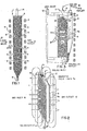
- the magnetically stabilized cross-flow contactor comprises a casing 1 (preferably nonmagnetic, not shown) and a contacting chamber 2 (preferably nonmagnetic) which contains a plurality of solid discrete magnetizable particles 6.
- the particles are supplied to chamber 2 via port 14 and exit chamber 2 via port 16.
- the particles are magnetized by magnet means 4 comprising a plurality of electromagnetic or solenoid coils coaxially surrounding chamber 2. These coils may be energized by DC or AC current. It is preferred to employ nontime varying fields colinear to the external field (i.e., gravity).
- Direct current (DC) rather than alternating current (AC) is preferred to energize the electromagnetic coils because it requires less power than the AC energized electromagnetic coils.
- the gas to be treated from any suitable source flows through conduit 10 (not shown) and into chamber 2 via a plurality of openings 8.
- the gas passes through the magnetized particles 6 in a generally cross-flow manner (i.e., perpendicular to gravity and the applied magnetic field) and exits the chamber 2 through a plurality of openings 9.
- the processed gas may then be transported from the contactor via conduit 12 (not shown).
- Fig. 2 is a left-side perspective view of the magnetically stabilized cross-flow contactor as shown in Fig. 1, which additionally includes a plurality of panel type louvers for the entry and exit of the gases to be contacted in the contactor.
- the solids 6 enter at 14 into contactor 2.
- the bed of magnetizable particles 6 moves down through the contactor 2 in a controlled manner while under the influence of the magnetic field 4a created by the magnet means (not shown).
- the gas from a suitable source, not shown enters an inlet means 10, not shown, and passes by the panel louvers 8a into the openings 8 into the contactor 2.
- the gas exits through the openings 9 and the solids particles are retained in contactor by the action of the magnetic field and the upwardly extending paralleled louvers 9a, whereupon the gas is withdrawn via gas outlet 12 (not shown).
- Fig. 3 is a cross-sectional view of the right half of an annular design using the cross-flow contactor of Fig. 1, which additionally includes inlet 18 and outlet 20 plenums for the contactor.
- Fig. 3 also shows a plurality of panelled louvers each adjacent the openings means 8 and 9 in communication with the gas inlet plenum 18 and gas outlet plenum 20. These louvers are arranged to extend outwardly from below their adjacent openings and into the inlet or outlet plenums to expose to the contacting chamber a plurality of free surfaces of the solid particles.
- the panelled louvers are arranged cooperatively to support the solid, discrete, magnetizable particles and retain the particles within the contacting chamber 2.
- the upward angle of the support members will preferably be adjusted based on the angle of repose of the magnetized particles within the contactor 2. Obviously, this will depend on the size and shape of the particles, the degree in which they are magnetized, the size of the openings 9 and the superficial velocity of the gas passing through the contactor 2.
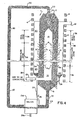
- Fig. 4 illustrates a cross-sectional view of another embodiment of the invention as shown in Figs. 1, 2 and 3.
- the gas to be contacted enters port 10 whereupon it enter into a common inlet plenum 18.
- the gas from plenum 18 then enters the openings 8 in the pair of substantially upwardly extending horizontally spaced-apart perforate retaining walls into the contacting zone 2, whereupon the gas exits through opening means 9 into the outlet plenum 20.
- Adjacent to the openings 8 and 9 are louvers 8a and 9a.
- the effluent gas from the outlet plenum 20 then is suitably transported from the contactor via port 12.
- the magnetizable particles 6 pass downwardly through the contacting vessel 2 first passing through a seal zone 36 which acts to prevent gas from leaking upward into vessel 2 and then into cross-flow zone 34.
- the porosity or voidage in the bed, the velocity of descent of the particles and the relative magnetization M of the particles themselves is controlled by the applied magnetic field from the magnet means 4 coaxially surrounding the vessel 1.
- the magnetizable particles may be caused to move downward in a continuous, semicontinuous or batchwise manner simply by the control of the valve means above and below vessel 1 designated as valve 32 and valve 22.
- the valve means may be any suitable valve, but may include an electromagnetic valve such as disclosed in U.S. Patent No. 3,067,131 to Bergstrom.
- the angle of the exit region 16 of the contacting vessel 1 is such that the magnetizable particles do not substantially stick to the sides of the vessel as they flow downward.
- the particles suitably pass through valve 22 into conduit 24 whereupon they are preferably passed through a solids regenerator 28. From time to time solids may leak from louvers 9a into outlet plenum 20 and these solids are suitably removed by conduit 26 into conduit 24 for further processing. The regenerated solids from solids regenerator 28 may then be recycled to contactor 2 via valve 32 and conduit 14.
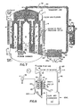
- Fig. 5 illustrates a combination cross-flow (radial flow) -raining solids contactor for countercurrent contacting of gas and solids which also has the capacity of removing particulates entrained in a gaseous stream in an expanded dense bed cross-flow region 34a.
- the contactor of Fig. 5 possesses a raining solids reactor/contactor zone 36a.
- the contactor/reactor scheme shown in Fig. 5 is a cross-sectional schematic representation of a contactor/reactor and process for carrying out simultaneously sulfur oxide and particulate removal using a magnetic sulfur oxide absorbent.
- the gas to be processed e.g., a flue gas containing sulfur oxides, nitrogen oxides and entrained particulates enters gas inlet 10 and into plenum 18 at the bottom of the contactor.
- Ammonia and air are injected into the gas stream to convert the nitrogen oxides to nitrogen and water.
- the flue gas enters on the inside of an annular conic section 18.
- the dirty flue gas passes in a cross-flow or radially through the annular section 2a through openings 8 having louver means 8a and out of openings 9 past louver means 9a and the cleaned gases then pass into a plenum chamber 20.
- the contactor is coaxially surrounded by electromagnetic coils 4.
- the magnetic sorbent particles 6 flow in a downward direction by the action of gravity and into the radial flow expanded zone 34a.
- the particles are preferably in a stiffened and expanded state by the action of the magnetic field generated by the electromagnetic coils.
- Fig. 5a illustrates a blown-up view of a portion of contactor 2a.
- the void fraction in the annular space 2a can be adjusted from approximately 0.35 to 0.7 depending upon the magnetic field strength of the electromagnetic coils and the cross-flow superficial gas velocity.
- the thickness of the annular zone 2a is designed to give the filtering efficiency and pressure drop required to remove 90-99% of the particulate matter entrained in the gas stream.
- the gas in plenum 20 enters the raining solids zone 36a and the cross-flow transition zone 35.
- a fixed interface 35a is maintained between the raining solids zone 36a and the radial flow expanded zone 34a.
- the magnetic solids have a tendency to form tree-like structures which collapse and form a greatly expanded stiff bed which gives a very low pressure drop.
- the void fraction is controlled by the magnetic field at the interface. By varying the magnetic field from electromagnetic coils 4 and 4b in different regions, one is able to control the void fraction in radial flow expanded zone 34a.
- the partially processed flue gas from plenum 20 then flows countercurrent to the falling solids 6 in the raining solids zone of contactor 54.
- This mode of processing provides an efficient cleanup of the flue gas. Simultaneously very fine particulates which escape through the cross-flow capture zone are captured by the falling magnetizable particles which have been electrostatically charged by electrostatic means 52 powered by a suitable'power source 50 prior to entering the raining solids zone 36a.
- the processed flue gas then leaves the raining solids zone to the stack via port 12.
- solids are continuously removed from the cross-flow zone via conduit 24 to maintain the interface between the two zones.
- the spent adsorbent particles containing fly ash are transported to the fly ash removal zone 28 where the fly ash is removed from the adsorbent particles.
- the fly ash is removed from the fly ash removal zone via port 28a.
- the fly ash may be removed from the magnetizable particles by various techniques such as elutriation, screening, magnetic separation, etc.
- the fly ash-free magnetizable particles are then transported to a countercurrent regenerator 36 optionally stabilized by electromagnetic coils 4a where the adsorbent is regenerated with a reducing gas supplied from conduit 37.
- the magnetizable particles may comprise an acceptor composition capable of accepting (or fixing) sulfur dioxide.
- Such an acceptor composition may comprise copper or a copper compound or mixture thereof supported on a particulate carrier, and may comprise, e.g., copper on magnesium oxide- stabilized AI z 0 3 .
- a typical magnetic absorbent is prepared by encasing magnetic particles such as 410 stainless steel within copper-impregnated alumina. These particles will have a particle size of 0.001 to 0.01 cms (10-100 ⁇ m) size range. Since the sorption reaction is diffusion controlled, advantages are seen when the copper sorbent is impregnated on an alumina which has approximately 50% of its pore volume in pores > 10- 5 cms ( > 1000 A) diameter.
- the flue gas desulfurization catalyst particles may be regenerated by treatment in a steam and hydrogen atmosphere where the absorbed CuS0 4 resulting from the S0 2 absorption is converted to Cu, water and SO 2 .
- the regenerator possesses electromagnetic field coils 4a to optionally impose a magnetic field within the regenerator.
- the concentrated S0 2 effluent from the regenerator is removed by conduit 39 for further processing, e.g., conversion to sulfur.
- the regenerated magnetizable catalyst particles are then returned to the top of the raining solids zone 54 via conduit 14 in a controlled manner by valve 14a where they are electrostatically charged for removing fine particulates entrained in the incoming gas.
- the electromagnetic field coil 4b which is coaxially positioned around the raining solids zone insures uniform distribution of the solids across the raining solids zone.
- the contactor system of Fig. 5 which has been described specifically for flue gas desulfurization can be used for a plurality of other operations where it is desirable to use a combination of long and short contact time with catalytic solids. Also, heating and cooling can be carried out in the cross-flow and raining solids zones, respectively. In addition, it is possible to carry out two reactions in the contactor of Fig. 5, i.e., one in the dense, cross-flow zone and the other in the raining solids zone.
- Fig. 6 is a top elevational view of a multipanel bed contactor useful in the practice of the invention. It can be seen from Fig. 6 that the pairs of perforate walls of adjacent chambers or panels 2 are arranged so as to be like the pleats of an accordion.
- the gas to be contacted enters into plenum 18 and passes through a plurality of panels 2 containing the magnetizable particles 6 and into outlet plenum 20.
- the panels are encased by casing 1 comprised of a gas inlet duct in communication with plenum 18 and a gas outlet duct in communication with plenum 20.
- Electromagnetic coils 4 coaxially encase the unit so as to produce a substantially uniform magnetic field.
- panel beds arranged in this manner can be from 3.048 to 18.288 m (10 to 60 feet) in height and occupy a space of 5.08 to 30.48 cms (2 to 12 inches), preferably 15.24 to 25.4 cms (6 to 10 inches) wide. It will be appreciated by those skilled in the art that if one operated at a face velocity of greater than 30.48 cms/s (1 ft./sec.), extremely high contacting per unit volume can be realized by use of this contactor.
- Fig. 7 is a front cross-sectional schematic view of a cross-flow or panel bed contactor 1.
- This contactor is suitable for use in a flue gas desulfurization process and other chemical conversions.
- the flue gas can typically enter into gas inlet plenum 18.
- the flue gas can then be processed by passing in a cross-flow manner into the magnetically stabilized cross-flow bed 2 through openings 8 containing the magnetizable particles 6 which are capable of absorbing S0 2'
- the clean flue gas leaves the bed of magnetizable particles through openings 9 and into outlet plenum 20 and outlet port 12.
- the spent magnetizable particles 6 in bed 2 are transported downward through the contactor 2 in a controlled manner via valve 22.
- the voidages in contactor 2 and the degree in which the particles are magnetized are controlled by the applied magnetic field from the magnet means 4.
- the magnetic field also prevents gas entrainment and blowout of the solids.
- the spent magnetizable particles are removed from the contactor 2 via conduit 16 through valve 22 and into separator 28, e.g., a fly ash vibrating screen 29.
- the separated fly-ash 29a can be removed by exit port 28a and the separated particles can be moved pneumatically through conduit 30 to the sorbent regenerator 36 via conduits 34 and 38 and returned to conduit 30.
- Treatment in the regenerator is the same as described for Fig. 5.
- the regenerated magnetizable particles may be used in processing fresh flue gas by control of valve 32 and allowing the particles to be transported through conduit 14 into vessel 1.
- the cylindrical steel pressure vessel 1 is comprised of hemispherical heads in which there are contained three concentric chambers of 3.048 m, 3.353 m and 4.072 m (respectively 10, 11 and 15 feet) average diameter and 5.096 m (20 feet) high for a total area of 2.083 m 2 (2240 square feet).
- the chambers are formed by perforated pipes, or pipe stubs attached to woven, nonmagnetic stainless steel cloth, and contain the magnetic particles which may vary in size from 0.02 to 0.0750 cms (200 to 750 microns).
- the magnetic particles 6 are of high surface area material and contain a suitable catalyst for the absorption of S0 2'
- This magnetizable catalyst may be 410 stainless steel particles coated with alumina which contains copper. The SO in the flue gas is reacted with the copper and oxygen from the flue gas to form copper sulfate.
- the magnetic catalyst particles which fall vertically, in the annular gaps between adjacent perforated pipes, are maintained in an expanded, but packed, configuration by a series of magnetic coils 4 which are stacked upon each other and separated by a reasonable distance.
- the highly expended bed of magnetic particles should be controlled to provide a voidage fraction of 0.35-0.7, the control being made by the applied magnetic field and the gas flow rate. Since the magnetic particles are essentially "locked" to each adjacent particle by the inter-particle magnetic forces, the moving bed of particles resembles a continuous mechanical filter of adjustable voidage or porosity.
- the head pressure acting on the vertical columns of magnetic particles keep the particles in a downward direction to a vibrating, or oscillating screen separator 28.
- the particulates which have been captured by the magnetic particles are mechanically separated in separator 28.
- the particulate-free magnetic catalyst particles are then preferably treated in the catalyst regenerator 36 with steam, CO and hydrogen where the CuS0 4 is converted to CuO and SO 2 .
- the magnetic catalyst particles are rejuvenated they are transported via pneumatic means in conduit 30 to the top of the contactor via conduit 14 where they begin their downward fall, in a controlled manner, through the annular gaps which exist between the three different pipe pairs.
- the pressure drop can be estimated from the following Ergun fluid dynamics relationship tor pressure drops in packed beds:
- Fig. 8 illustrates a partial cross-sectional frontal view and schematic process description of using the magnetically stabilized cross-flow bed contactor in a combined cycle power system.
- coal is transported to a fluid bed combustor 40.
- the flue gas frpm the fluid bed combustor is passed into the magnetically stabilized cross-flow contactor via conduit 10 into plenum 18 through the magnetized particles 6 and then into plenum 20.
- the clean flue gas from plenum 20 exits through conduit 12 into the turbine/generator 42 (which also supplies the power to run compressor 44).
- Air is supplied to the fluid bed combustor through conduit 46 from compressor 44.
- the spent solid particles from the magnetically stabilized cross-flow contactor are transported through conduit 16 into separator 28 whereupon they are recycled to the contactor via conduit 30.
- the concentrated effluent from the elutriator is then further processed in cyclone 36 to remove particulates.
- Typical conditions for the process include processing a flue gas of 815.6 to 927°C (1500-1700°F.) and at pressures of 5-20 atmospheres.
- the flue gas contains about 2.29 to 45.8 x 10- 3 g/litres (1-20 grs/SCF) of fly ash.
- Fig. 9 illustrates an improved louver design of the magnetically stabilized cross-flow contactors similar to those shown in Fig. 1 to 7.
- a "A"-shaped inlet louver 8b is shown where the louver extending from the contactor extends outward and upwards into plenum 18, preferably at an angle greater than about 45° to the horizontal, and a portion (preferably about one-half) of the louver extends further outward and downward, preferably at an angle greater than 45° to the horizontal.
- This improved louver design is particularly useful when removing particulates with the magnetically stabilized cross-flow bed where uniform distribution of the gas to the moving magnetically stabilized bed, the prevention of plugging, and the achievement of very low pressure drops over the entire reactor section are desirable.
- Fig. 10 illustrates another improved design of the magnetically stabilized cross-flow contactor.
- support means 11 e.g., rods, angle irons, vertical bars, incline bars, rods on a triangular pitch, etc.
- support means 11 e.g., rods, angle irons, vertical bars, incline bars, rods on a triangular pitch, etc.
- stabilization of the solids can be increased in these areas.
- the distance between the louvers can be increased substantially.
- This improved design is particularly useful where large panels ranging from 3.048 to 15.25 m (10 to 50 feet) high and 10.16 to 30.48 cms (4 to 12 inches) thick will be employed.
- Such panel contactors will require the use of a very high column of solids moving down the panel which will generate a considerable pressure head and weight on the louvered paneled section.
- the support means 11 shown in Fig. 10 higher gas velocities and improved solids flow can be obtained in the magnetically stabilized cross-flow beds.
- the support means will stabilize the solids flow and support part of the weight of the moving solids in the contactor.
- the support means may be ferromagnetic, weakly ferromagnetic or nonferromagnetic.
- This example illustrates that one can operate at substantially higher superficial gas velocities before blow-out by use of small magnetizable solids in a magnetically stabilized gas cross-flow contactor.
- the contactor consists of an upstanding rectangular plexiglass container similar to that shown in Fig. 2.
- the contactor is 43.18 cms (17 inches) high, 20.32 cms (8 inches) thick in the direction of gas flow and 2.54 cms (1 inch) wide.
- the contactor contains six louvered openings on the lower 11.59 cms (4 9/16 inch) portion of the contactor.
- the louvers are set at 45° to the horizontal spaced 1.905 cms (3/4") center to center measured vertically.
- the plexiglass louvers are about 3.56 cms (1.4 inches) long in the direction of the gas flow and 1.588 mm (1/16 inch) thick. After filling solids container 2 with the magnetizable solids it was sealed at the top and bottom.
- Each face of the contactor formed by the louvers is encased with plenum means 18 and 20, one of which is connected to a gas inlet source and the other means for withdrawing the gas. Pressure drop measurements were taken from the pressure. taps attached to the inlet and outlet plenums at the center of each of the louver spaces.
- the contactor was placed within ten magnetic coils stacked on top of each other having an internal diameter of 39.88 cms (15.7 inches), an outer diameter of 64.26 cms (25.3 inches) and about 55.88 cms (22 inches) in height.
- Each coil had 270 turns of a conductor 2.54 cm (1 inch) high x 0.025 inch thick and insulated with 5.08 x 10- 3 cms (2 mill) Mylar * 2.54 cm (1 inch) wide between turns. 15.24 x 10- 3 cms (Six mills) of Mylar was positioned between the solenoid coil section and support plate.
- the inductance was 18.1 mH (with air core) and a resistance of 0.296 ohms.
- the coils were placed in a support structure.
- the solids container of the contactor was filled to the top with magnetizable solid particles comprising 4 x 10- 3 cms (40 micron) 410 stainless steel particles encased in AI 2 0 3 , the composite having an average mean diameter of about 0.09 cms (900 microns).
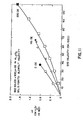
- Air was metered into the inlet plenum and allowed to exit the outlet plenum. Pressure drop measurements were taken at various levels of superficial gas velocities. The air supply was increased starting at zero magnetic field until blow-out of solids occurred. Blow-out velocity was noted at the superficial gas velocity at which the magnetizable beads began to continuously fall into the outlet plenum. Data were taken at zero, 165 and 320 oersteds applied magnetic field. The results of the experiments are shown in Fig. 11.
- This example further illustrates that higher gas velocities, before solids blow-out, can be practiced by use of the magnetically stabilized gas cross-flow contactor than with an unstabilized gas cross-flow contactor.
- three different contactors having three different louver angles were used. Except for the angle of the louvers, the contactors were similar to the one shown in Fig. 2.
- Each of the contactors were 78.92 cms (31 1/4 inches) high, 8.414 cms (3-15/16 inches) thick in the direction of the gas flow and 3.65 cms (1 7/16 inches) wide.
- the contactors having louvers 8a and 9a at angles of 30° and 45° to the horizontal had six openings.
- the contactor with 60° angle louvers had four louvers (with three openings) on each side of the contactor.
- the louvers in each of the three contactors was 3.56 cms (1.4 inches) long in the direction of gas flow and 0.0625 cms (1/16 inch) thick.
- the open face provided by these louver arrangements was 11.11 cms (4 3/8 inches) high in each of the three contactors.
- Inlet and outlet gas plenum 18 and 20 walls were spaced about 1.905 cm (3/4 inch) from the outer edge of the louvers and 3.175 cms (1 1/4 inch) from the solids retaining wall of the contactor. Pressure taps were located approximately central to the louver openings in the inlet and outlet plenums.
- Tests were made using two magnetic modules for applying a field to the three contactors described above. With reference to Table I the first eight tests listed involved the use of the same field generating coil which was used in the tests involved in Example 1. The remaining sixteen tests listed in Table I utilized, for magnetic field excitation, a single solenoid winding 42.545 cms (16.75 inches) in height and comprising 16 layers of 119 turns per layer, said turns being made with No. 8 square copper wire encased in varnish impregnated insulation. The windings were connected in series-parallel combination to permit excitation by a direct current power supply having an output rating of 50 ampere maximum and 50 volts maximum. The solenoid was wound on an aluminum spool having an internal diameter of 19.685 cms (7.75 inches).
- Example 1 Several blow-out velocity tests were carried out as in Example 1, i.e., placing each of the three contactors within above-described magnet modules and introducing air into the filled contactors.
- the following table illustrates the results of these tests which show the blow-out velocity for each of the three above-described contactors at different field strengths and particle compositions.
- the superficial velocity both at the face of the louver and in the bed
- solids blow-out increases with increasing magnetic field strength.
- the contactor used in this experiment was identical to the contactor used in Example 2 having 45° angle louvers.
- the magnet modules used are described below.
- the magnet modules were comprised of 12 separate coils stacked on top of one another at a spacing of about 6 cm. so that the bed could be visually observed.
- the coils were 20.3 cm. internal diameter magnetic modules and occupied a height of 96.5 cm.
- the water cooled modules were 4.13 cm. thick and 71.1 cm. outside diameter.
- Each module consisted of 72 turns of square cross-section copper tubing which had a circular bore and which were capable of dissipating 60 KW with a cooling water flow rate of 6.8 liters per minute.
- the maximum center line field strength obtained with the 12 modules connected in series was about 2200 oersteds at an applied current of 250 amperes.
- the modules at either end were spaced 0.63 cm. apart while the spacing between the remaining 8 modules was 6.03 cm.
- the two modules at either end of the stack were connected in series to separate power supplies so their current flow could be varied independently of the remaining 8 modules.
- the 8 centrally located modules were connected in series to a third power supply.
- the contactor was filled with cobalt particles having an average mean diameter of about 0.09 cms (900 microns).
- Air containing 3.8897 x 10- 3 g/litre (1.7 grains/SCF) of nominal fly ash particulates was passed through the magnetically stabilized cross-flow gas contactor containing the cobalt particles at a superficial gas velocity of 94.5 cm./sec. at 0, 30 and 105 oersteds of applied magnetic field.
- the air containing the fly ash particulates was fed to the contactor by use of a particulate feeder.
- the particulate feeder utilized was a grooved rotary disc feeder (BIF, Buffalo, R.I., the Omega model 22-01) which metered the particulates flow by varying the rotational speed of the disc.
- the particulate feeder was calibrated with 0 to 50 x 10- 3 cm (0-50 micron) fly ash which was sieved from a drum of fly ash obtained from a fluidized bed coal combustor (FBCC).
- FBCC fluidized bed coal combustor
- the fly ash particulate feed rate could be varied from zero to 15.65 gm./min. by varying the transmission speed of the feeder.
- the linear plot of transmission speed as a function of fly ash feed rate was found to be reproducible within ⁇ 2% over the entire range of feed rates.
- An off-gas system was connected to the outlet plenum to a combination of Balston * filters. Downstream from the Balston filters the cleaned air went into an exhaust duct which was vented to the atmosphere. The entire off-gas system was fabricated from 5 cm. ID, clear polyvinylchloride pipe so that any accumulation of particulates on the walls of the pipe could be observed.
- the modified Balston filters which consisted of a fiberglass element contained in a transparent acrylic vessel were utilized to determine the gross particulate capture efficiency of the capture bed.
- the filters were modified by reversing the flow through them; the flow path was from the inside of the filter element to the outside.
- the support core for the element was removed and the element-end-seals were held in place with two elastic bands. In this manner, none of the particulates ever deposited on the inner wall of the acrylic shell.
- the particle size distribution in the range of 1.1 x 10- 4 to 7.0 x 10- 4 cm (1.1-7.0 microns)
- the flow could be diverted by means of a two-way ball valve, for a predetermined period, through modified Anderson impactors.
- the Anderson impactor contained four stages and a final filter having effective cut-off diameters ranging from greater than 7.0 x 10- 4 cm (7 microns) to less than 1.1 x 10- 4 cm (1.1 microns) in the final filter at 566 liters/min. flow rate.
- the conventional Anderson impactor was modified slightly by the addition of a particle * "Balston” is a registered trade mark fractionator which limited the size of the particles impacting upon the first stage, to 11 x 10- 4 cms (11 microns). This was necessary in order to prevent overloading of the first stage with large particulates which would be re-entrained and carried over to the second stage.
- the maximum loading of any one stage of the Hi-Vol Anderson impactor was 0.075 gm. ⁇ 10%. If this loading were exceeded, the particle size cut off data would be questionable.
- the particle fractionator which was incorporated into the impactor was designed from published data (Willeke, K. and McFeters, J., "Calibration of the Champ Fractionator,” (Final Report) Particle Tech. Lab. Dept. of Mech. Eng., Minneapolis, Minn. 55455, March, 1975, Publication No. 252).
- the preweighed Balston filter elements were removed and their weight change measured on a precision balance that had a sensitivity of 0.001 gm.
- Fly ash that had accumulated on the walls of the off-gas system was collected and weighed.
- the bed material which now contained the fly ash captured after each experiment, was removed from the reactor and weighed. After weighing the bed it was necessary to separate the 0 to 50 x 10- 3 cm (0-50 micron) fly ash from the 0.9 mm (900 micron) cobalt particles. This was accomplished via mechanical sieving in a vibrating sifter.
- the fly ash-cobalt mixture was screened through a sieve for a short period. Upon inspection of the sieve material under a microscope it was determined that all the fly ash had been removed from the cobalt.
- the fractions of fly ash and cobalt were weighed, a mass balance and bed capture efficiency computed.
- the capture efficiency for the bed of each experiment was determined by comparing the total weight of fly ash actually fed to the contactor (a weight measurement) as determined from an ash feeder calibration curve, less the ash found in the inlet plenum, to the sum of the fly ash collected in the Balston filters and accumulated in the off-gas lines upstream of the filters.
- the fly ash material balance was calculated from the ratio of total fly ash fed to the contactor (obtained from a calibration curve) to the total fly ash accumulated in the bed (the fly ash was removed from the cobalt bed solids by a vibrating screen device, e.g., a Sonic Sifter), the off-gas piping and the Balston filters.
- the capture efficiency was calculated by two methods:
- Fig. 12 The results of these static bed particulate capture tests are shown in Fig. 12 wherein the capture efficiency data is plotted against time (minutes). As shown in Fig. 12 the capture efficiency drops off very rapidly at 0 applied magnetic field. An improvement in capture efficiency occurs at 30 oersteds of applied magnetic field and a dramatic improvement in capture efficiency occurs at 105 oersteds applied magnetic field. Thus, the applied magnetic field not only enables one to use higher gas velocities before blowout, as shown in Examples 1 and 2, it also improves the capture efficiency of a gas cross flow contactor.
- magnetically stabilized gas cross-flow contactor can be used in a continuous manner as a particulate capture device.
- the contactor and magnet modules used in this experiment were identical to the contactor used in Example 3.
- the contactor was modified to the extent that it had a valve means above and below the contactor to control the solids input and output.
- the magnetizable solids (cobalt, having a mean diameter of 0.590 mms (590 microns)) were added to a solids hopper above the contactor.
- the contactor was filled by opening the inlet valve and closing the solids outlet valve.
- the solids exit the contactor through a vertical standpipe upon opening the solids opening valve whereupon the solids are transported to a solids elutriator to separate the fly ash from the solids and then pneumatically transported up a pipe to a cyclone and down into the solids hopper. In this manner the solids can be moved throughout the entire system in a controlled and continuous manner.
- Example 2 The tests in this example, other than the solids circulation, were conducted in a manner similar to that described in Example 3. Dried air containing fly ash was fed to the contactor by use of the rotating disc calibrated feeder. The outlet gas was fed to an "Octopus" Balston filter manifold. Table II summarizes five (5) runs using the circulating bed at 120 and 100 oersteds of applied magnetic field. As shown from the data in Table II, the following advantages are manifested by use of the solids circulating magnetically stabilized gas cross-flow bed;
- Tests were carried out to determine the effects of particle size on copper utilization in a simulated flue gas desulfurization process.
- sorbent A was a conventional sized copper surface impregnated porous alumina prepared as described in U.S. Patent No. 3,985,682. More particularly, sorbent A was prepared as follows: 1.27 cm (t inch) O.D. cylindrical ring extrudates (having 0.635 cm (1/4 inch) holes) of acetic acid peptized porous alumina previously calcined for 3 hours at 1000°F (B.E.T. surface area, about 180 m 2 /g; a pore volume of about 0.40 cc/g) were immersed in a mixture of isomeric C 6 alcohols (oxo alcohols) for 1 hour.
- the extrudates were removed from the alcohol solution, drained of excess alcohol and were then immersed in a solution of Cu(NO 3 ) 2 .3H 2 O and MgNO 3 to provide approximately 5 wt. % Cu and 0.3 wt. % Mg on A1 2 0 3 in the region actually impregnated by the Cu(N0 3 ) 2 and MgN0 3 solution.
- the extrudates were permitted to remain in the solution until the alcohol was displaced to a depth of 0.0889 cms (0.035 inches) by the Cu as described in U.S. Patent No. 3,985,682.
- the extrudates were then removed from the copper nitrate solution, drained, blotted dry and dried in a forced air drying oven overnight at about 90.6°C (195°F).
- the nitrates were decomposed to oxides by calcining under air at 426.7°C (800°F) for about 3 hours.
- Sorbents B-1, B-2 and B-3 were prepared in the same manner as Sorbent A (the alumina had a B.E.T. surface area of 247 m 2 /g; pore volume of 0.54 cc/g.) except that the alcohol immersion step was omitted since total copper impregnation was desired with the smaller particles.
- the copper impregnated extrudates were crushed and screened to three different sizes, 80/100 mesh (average particle size 160 x 10- 4 cm (160 microns)), 42/60 mesh (average particle size 0.33 mms (330 microns)) and 10/20 mesh (average particle size 1.4 mm (1400 microns)) for Sorbents B-1, B-2 and B-3 respectively.
- the sorbent particles were then tumbled for 1/2 hour to remove the rough edges and then rescreened.
- the final Cu analysis for each of the three sizes of particles was 4.54 wt. %, 4.78 wt. 96 and 4.90 wt. %, for Sorbents B-1, B-2 and B-3, respectively, for Cu and Mg the analysis was about 0.3 wt. % for each of the three particle sorbent sizes.
- the testing unit consisted of a sandbath heated 16 mm quartz reactor of downflow design.
- the gas feed blend (measured by rotameters) plus water was introduced at the inlet tube and passes down to near the bottom of the reactor, up through a preheating coil and entered the reactor above the sorbent.
- the gas flow continued downward through the sorbent bed and out the gas exit line through a knockout pot to an S0 2 analyzer (air pollution monitor manufactured by Dyansciences Corp. equipped with a 55-330 sensor). Provision was made for by-passing the reactor so as to permit analysis of the feed gas.
- the simulated flue gas had the following approximate volume percent composition:
- the simulated processes were carried out by placing about 20 cc volume of the test sorbent in the reactor placed in the sandbath and brought to a temperature of 371.1 OF (700°F).
- the SO 2 analyzer was checked against a certified Matheson SO 2 gas blend as standard.
- the feed gas blend was checked for proper S0 2 content and the gas rate (3 liters/1 minute) was checked using a wet test meter.
- Water was fed by a Ruska pump and vaporized in the reactor inlet preheater.
- the sorption was carried out at atmosphere pressure. Prior to starting the sorption cycle the reactor was lined out with all gases and water except S0 2 passing over the sorbent.
- Lime (calcium oxide) is also a feasible SO 2 sorbent in a non-regenerative process.
- the lime sorbent useful in the practice in the present invention is a physical mixture of a fluidizable magnetic substance (e.g., stainless steel, cobalt, cobalt alloys, etc.) and lime.
- the sulfated or sulfited lime after separation is not regenerated.
- lime it is advisable to use relatively higher temperatures, e.g., 482.2°C (900°F) and higher, particularly for smaller particle sizes, e.g., 20-60 mesh lime particles. At the higher temperatures, however, care should be directed to selection of the magnetic particles so that the curie point of the magnetic particles is not encountered at the operating temperatures.
- flue gas desulfurization sorbents may be utilized in the magnetically stabilized cross-flow contactor.
- the cerium oxide sorbent disclosed in U.S. Patent No. 4,001,375 may be used as a composite or in admixture with suitable magnetic particles.
- the flue gas may be contacted with the cerium oxide-magnetic composite or admixture at a temperature ranging from 300°C to 800°C to form cerium sulfate and/or sulfite and regeneration of the sorbent can be accomplished by contacting the sorbent with a reducing gas, for example, hydrogen is admixture with steam or other inert gases at a temperature ranging from 500°C to 800°C to convert the cerium sulfate or sulfite to cerium oxide.
- the desorbed species is initially sulfur dioxide. However, when about 50% of the sulfur is removed from the sorbent, the desorbed species becomes H 2 S.
- an admixture of S0 2 and H 2 S are provided with the excess reducing gas, which can be fed conveniently to the Claus plant for conversion into elemental sulfur.
- the cerium oxide will be on an inert support.
- the unsupported cerium oxide will preferably have a B.E.T. surface area of at least 10 m 2 /g, more preferably 20-40 m 2 /g.
- sorbents useful in the flue gas desulfurization in the magnetically stabilized cross-flow contactor comprises magnetic composites or admixtures of the sorbents disclosed in U.S. Patent No. 4,001,376.
- Such sulfur dioxide sorbents are comprising a porous gamma-alumina base, about 2-20 wt. % (based on alumina) of a coating of a refractory oxide such as titanium dioxide, zirconium dioxide, or silica, and an active material, such as copper oxide, which is capable of selective removal of sulfur oxides from a gas mixture.
- a simulated flue gas desulfurization process utilizing the magnetically stabilized cross-flow contactor was designed based, in part, on the fixed bed data in Example 5.
- the design basis consisted of treating a flue gas at a rate to the unit from a coal-fired boiler generating approximately 907.2 kg/h (2M Ibs/hr) of steam.
- the coal is Illinois No. 6, but with the ash level increased to match the flue gas from East Texas Lignite. This gives both the highest S0 2 and fly ash loadings.
- Coal and flue gas compositions and conditions are given below.
- the flue gas temperature is between 371.1 and 398.9°C (700-750°F). This temperature corresponds roughly to the temperature into the boiler air preheater.
- the magnetically stabilized cross-flow flue gas cleanup system is a dry sorbent process that simultaneously removes SO x , NO x , and particulates from flue gas.
- the system consists of a multipanel bed contactor (as shown in Fig. 6) where the SO x , NO x , and particulates are removed, an elutriator where particulates are stripped from the circulating catalyst and collected for disposal, and a regenerator where the sorbent is regenerated and S0 2 liberated for downstream recovery.
- the sorbent consists of 30 wt.% alumina spheres (impregnated with 5 wt.% copper) and 70 wt.% 410 stainless steel particles (which give the sorbent magnetic properties) having a particle density of 137 Ib/ft 3 (2.2 g/cm 3 ) and a bulk density of 1.209 g/cm 3 (75.5 Ib/ft 3 ).
- the particle size ranged from 250-1680 mm.
- Flue gas (stream 1) is taken from a boiler economizer section at 371.1 to 398.9°C (700-750°F) and mixed (stream 3) with NH 3 (stream 2) before entering (stream 4) the magnetically stabilized crossflow contactor.
- the ammonia acts to decompose the NO x via the following overall reaction:
- the flue gas flows cross-current at a superficial gas velocity through the panel area of 91144 cm/s (3 ft/sec) 152.4 cm/s (5 ft/sec) through the louvers) to a magnetically stabilized moving bed or sorbent, which is travelling vertically down the reactor panels having a thickness of 22.86 cms (9 inches).
- the temperature in the bed is about 748°F.
- the pressure drop in the bed is 38.1 cm (15 inches) of water (bed and louvers) and the maximum space velocity is 6500 V/V/H.
- the maximum catalyst dust loading is 3 wt. % and the maximum copper sulfation is 75%.
- the applied magnetic field is held at 300 oersteds by use of 5 magnet modules to provide a substantially uniform applied magnetic field over the entire length of the bed.
- the particulates are trapped by the sorbent spheres, the NO x decomposition is catalyzed, and S0 2 is adsorbed according to the reaction:
- Clean flue gas (stream 5) passes out of the reactor and on to the boiler air preheater, induced draft fan, and stack.
- the decomposition and adsorption reactions are both exothermic and the exiting flue gas leaves at 398.9 to 426.7°C (750-800°F).
- the magnetic sorbent from the reactor flows by gravity to the elutriator through magnetic lock hoppers on each panel which regulate the sorbent circulation rate and ensure even flow through the panels.
- fly ash collected in the reactor is elutriated from the sorbent with air at 60.96 to 91.44 cms/s (2-3 ft/sec.) (stream 7) and collected in cyclones via stream 8 for disposal.
- the temperature in the cyclones is about 376.7°C (710°F).
- Overhead (stream 17) from the cyclones recycles to the top of the reactor sorbent distributor. The fly ash is drawn off of the cyclones via stream 16.
- sorbent is transferred to the regenerator through an overflow line (stream 9).
- the fluid bed in the regenerator (having a bed temperature of 381.6°C (719°F) and a gauge pressure of 0.7031 kg/cm 2 (10 psig.)) is magnetically stabilized by the action of an electromagnet coaxially surrounding the regenerator vessel, and the spent sorbent flows downward through the regenerator bed, countercurrent to the regenerator gas (stream 10).
- the applied magnetic field on the regenerator vessel is 200 oersteds to provide a voidage of 0.6.
- the sorbent is regenerated by the following overall reaction:
- S0 2 from the regenerator passes overhead (stream 11) to downstream recovery in a Claus plant or sulfuric acid plant.
- the regenerated sorbent is transferred back (stream 12) to the reactor via a riser using aeration air (stream 13) and distributed to the panels via a transfer line (stream 14) by a small fluid bed above the panels.
- the solids and air from stream 13 are separated and the air is emitted via a transfer line (stream 15) where this line is joined with the sorbent distributor overhead (stream 18).
- Table IX below shows the design basis for the individual pieces of equipment in the flue gas desulfurization process described above in this example.
- the magnetically stabilized gas cross-flow contactor may also be used to remove particulates and other contaminates at high temperatures and pressures.
- the magnetically stabilized gas cross-flow contactor may be used to remove particulates and chemical contaminants from flue gas streams from a pressurized fluidized bed combustor (PFBC) at temperatures ranging from 815.6°C to 926.7°C 1500-1700°F. and pressures ranging from 5-20 atmospheres.
- PFBC pressurized fluidized bed combustor
- flue gas contains 8.8 x 10- 6 to 22 x 10- 6 g/cm 3 at 0°C and 1 atmosphere (4-10 grs/SCF) exiting from the combustor with a particle size distribution ranging from 1 x 10- 3 to 0.600 mms (1-600 microns). It is generally desirable to have a hot gas cleanup system having an overall collection efficiency of 99.9%. Additionally, graded efficiencies of 99.95% for particulates greater than 5 x 10- 3 mms (5 microns), 99.5% for particulates between 4 and 5 x 10- 3 mms (4-5 microns), and 99.5% for particulates less than 4 x 10- 3 mms (4 microns) should be removed.
- One way to accomplish the above particulate capture standard in a combined cycle power generation system under high temperatures and pressures is to slightly modify the schematic shown in Fig. 8 by incorporating cyclones in series between the fluid bed combustor and the magnetically stabilized cross-flow contactor.
- the purpose of the cyclones is to provide efficient and economical removal of particulates greater than 4 x 10- 3 mms (4 microns), thereby reducing the amount of material which must be removed by the magnetically stabilized cross-flow contactor. This will have a favorable impact in reducing the capital and operating costs since it will reduce the size and complexity of the "back end" equipment required for removing the captured flyash from the bed material.
- the cyclones also provide an effective margin of safety to prevent rapid catastrophic failure of gas turbine blades in the event of failure of the contactor.
- the magnetically stabilized gas flow contactor can easily accommodate an additional load resulting from cyclone failure, thereby, permitting shutdown and repair to the system without endangering the highly expensive gas turbines.
- the flue gas contains 2 to 5 ppm of alkali metal exiting the combustor.
- alkali metal scavengers in the form of metal oxides or mixed metal oxides, may be used to remove the alkali metals.
- suitable metal oxides are alumina, bauxite, alundum, silica gel, diatomaceous earth and Kaolin clay.
- scavenger materials may be suitably mixed with the cobalt-based magnetizable particles which are necessary to stabilize the panel bed with magnetic field.
- the amount of scavenger used will be sufficient to remove trace alkali metals to levels of less than 0.02 ppm by weight. However, this amount will preferably not exceed 25 wt.% of the total bed solids.
- the sorbent may be separated from cobalt-based materials using a magnetic separation. Although it may be possible to regenerate the scavenger for re-use, it is preferable to use the scavenger on a "once-through" basis. Because of the low concentration of trace metals in the flue gas, even a non-regenerable system would require modest amounts of scavenger material.
- flue gas from the high pressure fluid bed combustor at 0.4536 to 0.9072 kg/sec (1-2 Ibs/sec) of flue gas over a temperature of 815.6 to 926.7°C (1500-1700 0 F.) and a pressure range of 6-16 atm is passed through cyclones to remove the bulk of flyash/dolomite particulates.
- the flue gas then is passed into a magnetic cross-flow panel bed consisting of an admixture of ferromagnetic particles necessary to stabilize the bed and alkali metal scavenger particles such as bauxite or alumina.
- the stabilized moving panel bed acts as a filter for capturing particulate by impaction, interception or diffusion on the bed material. Trace quantities of sodium and potassium are removed by reaction or adsorption with the scavenger bed material. As the concentraton of flyash increases on the bed, it is removed from the bottom of the bed and circulated by a gas transfer line to, first, a rough cut cyclone, which removes any flyash which has been detached from the bed material and, then, to an elutriator where the remaining flyash is removed from the bed material. Bed material is returned to the magnetically stabilized bed while the dust laden gas from the elutriator is combined with the transfer line gas and sent to a cyclone where the dust is separated from the gas. The remaining gas is either cleaned further in a bag filter and sent to a stack or recirculated to the combustor as makeup air.
- Alkali metals can be picked up by non-magnetic scavengers which are admixed with the magnetic material.
- Another use for the magnetically stabilized cross-flow contactor of the invention involves using the same to control dust in grain elevators, flour mills and other operations with potentially explosive dust is a safety hazard.
- the presence of grain dust in grain elevators, flour mills and other agricultural and mining operations presents a potential safety problem.
- These problems may be handled by the use of the magnetically stabilized cross-flow contactor.
- air purge streams are used to remove dust from the silos, transfer points, loading facilities, etc. The air from these points passes through the magnetically stabilized cross-flow contactor in which the finely divided solids are removed from the air before it is discharged by an induced draft fan to the atmosphere.
- the gas flow in a cross-flow manner through a moving bed of magnetically stabilized solids.
- the solids are a very high density ferromagnetic material and can range in particle size from about 0.01 to 0.20 cms (100 to 2000 microns). Particle size is adjusted to control pressure drop and particulate capture efficiency.
- the solids from the filter pass through a moving grate or a vibrating sieve which is continuously contacted with suitable means to remove the dust. Solids pass from the grate or sieve and are transported back to the filter vessel. This system offers the advantages of a very high gas velocity with a very low pressure drop.
- the panel bed thickness may range from about 10.16 to 60.96 cms (4 to 24 inches) and superficial gas velocities up to and excess of 6.096 m/s (20 ft/sec.) can be achieved.
- a particular advantage of this system is that the grain dust is collected in a solid and is diluted so that it is non-explosive in the filtering operation.
- the solids are readily washed with a suitable liquid which removes the dust, e.g., water, from the magnetizable solids. The solids can be drained of the excess liquid and returned to the filter zone.
Landscapes
- Chemical & Material Sciences (AREA)
- Chemical Kinetics & Catalysis (AREA)
- Engineering & Computer Science (AREA)
- Analytical Chemistry (AREA)
- General Chemical & Material Sciences (AREA)
- Oil, Petroleum & Natural Gas (AREA)
- Organic Chemistry (AREA)
- Health & Medical Sciences (AREA)
- Biomedical Technology (AREA)
- Environmental & Geological Engineering (AREA)
- Combustion & Propulsion (AREA)
- Devices And Processes Conducted In The Presence Of Fluids And Solid Particles (AREA)
Claims (25)
Applications Claiming Priority (10)
| Application Number | Priority Date | Filing Date | Title |
|---|---|---|---|
| US62541 | 1979-07-31 | ||
| US06/062,557 US4254616A (en) | 1979-07-31 | 1979-07-31 | Process for flue gas desulfurization or nitrogen oxide removal using a magnetically stabilized fluid cross-flow contactor |
| US06/062,540 US4255166A (en) | 1979-07-31 | 1979-07-31 | Process for the removal of particulates entrained in a fluid using a magnetically stabilized fluid cross-flow contactor |
| US06/062,541 US4254558A (en) | 1979-07-31 | 1979-07-31 | Louvered magnetically stabilized fluid cross-flow contactor and processes for using the same |
| US62557 | 1979-07-31 | ||
| US06/062,539 US4254557A (en) | 1979-07-31 | 1979-07-31 | Magnetically stabilized fluid cross-flow contactor and process for using the same |
| US62539 | 1979-07-31 | ||
| US06/062,538 US4255403A (en) | 1979-07-31 | 1979-07-31 | Magnetically stabilized fluid cross-flow contactor having support means and process for using the same |
| US62538 | 1987-06-12 | ||
| US62540 | 1998-04-17 |
Publications (2)
| Publication Number | Publication Date |
|---|---|
| EP0024809A1 EP0024809A1 (de) | 1981-03-11 |
| EP0024809B1 true EP0024809B1 (de) | 1982-11-17 |
Family
ID=27535582
Family Applications (1)
| Application Number | Title | Priority Date | Filing Date |
|---|---|---|---|
| EP80302494A Expired EP0024809B1 (de) | 1979-07-31 | 1980-07-23 | Apparat für Querstromkontaktierung von einem Fluid mit Feststoffteilchen in einem magnetisch stabilisierten Bett dieser Feststoffteilchen und Verfahren zu dessen Verwendung |
Country Status (3)
| Country | Link |
|---|---|
| EP (1) | EP0024809B1 (de) |
| CA (1) | CA1130540A (de) |
| DE (1) | DE3061106D1 (de) |
Cited By (9)
| Publication number | Priority date | Publication date | Assignee | Title |
|---|---|---|---|---|
| RU195600U1 (ru) * | 2019-08-23 | 2020-01-31 | Аркадий Владимирович Владимирцев | Физико-химический реактор с вихревым слоем |
| RU195601U1 (ru) * | 2019-08-23 | 2020-01-31 | Аркадий Владимирович Владимирцев | Физико-химический реактор с вихревым слоем |
| RU195803U1 (ru) * | 2019-08-23 | 2020-02-05 | Аркадий Владимирович Владимирцев | Физико-химический реактор с вихревым слоем |
| RU197602U1 (ru) * | 2019-08-23 | 2020-05-15 | Аркадий Владимирович Владимирцев | Физико-химический реактор с вихревым слоем |
| RU197601U1 (ru) * | 2019-08-23 | 2020-05-15 | Аркадий Владимирович Владимирцев | Физико-химический реактор с вихревым слоем |
| RU198283U1 (ru) * | 2019-08-23 | 2020-06-30 | Аркадий Владимирович Владимирцев | Физико-химический реактор с вихревым слоем |
| RU2725655C1 (ru) * | 2019-09-23 | 2020-07-03 | Аркадий Владимирович Владимирцев | Физико-химический реактор с вихревым слоем и ферромагнитная частица для такого реактора |
| RU2725657C1 (ru) * | 2019-09-23 | 2020-07-03 | Аркадий Владимирович Владимирцев | Физико-химический реактор с вихревым слоем и ферромагнитная частица для такого реактора |
| RU2729078C1 (ru) * | 2019-09-23 | 2020-08-04 | Аркадий Владимирович Владимирцев | Физико-химический реактор с вихревым слоем |
Families Citing this family (10)
| Publication number | Priority date | Publication date | Assignee | Title |
|---|---|---|---|---|
| EP0083825A1 (de) * | 1982-01-04 | 1983-07-20 | Exxon Research And Engineering Company | Verfahren zur Rückgewinnung von Wasserstoff |
| NL9001138A (nl) * | 1990-05-15 | 1991-12-02 | Stork Ketels Bv | Gaskanaal met een reinigingseenheid. |
| US10502136B2 (en) * | 2014-10-06 | 2019-12-10 | Bha Altair, Llc | Filtration system for use in a gas turbine engine assembly and method of assembling thereof |
| RU2614009C1 (ru) * | 2015-12-14 | 2017-03-22 | Федеральное государственное бюджетное образовательное учреждение высшего профессионального образования "Кубанский государственный аграрный университет" | Аппарат вихревого слоя |
| RU2613517C1 (ru) * | 2016-03-21 | 2017-03-16 | Федеральное государственное бюджетное образовательное учреждение высшего профессионального образования "Кубанский государственный аграрный университет" | Аппарат вихревого слоя непрерывного действия |
| RU2614013C1 (ru) * | 2016-03-21 | 2017-03-22 | Федеральное государственное бюджетное образовательное учреждение высшего профессионального образования "Кубанский государственный аграрный университет" | Аппарат слоя вихревого |
| RU182051U1 (ru) * | 2018-03-22 | 2018-08-01 | Федеральное государственное бюджетное образовательное учреждение высшего образования "Кубанский государственный аграрный университет им. И.Т. Трубилина" | Установка проходная вихревого слоя |
| CN110141918B (zh) * | 2019-05-22 | 2024-11-15 | 内蒙古科技大学 | 一种多通道复合电磁过滤除尘装置 |
| CN111389165A (zh) * | 2020-05-11 | 2020-07-10 | 朱彬苇 | 一种渐落型气体多层滤尘装置 |
| CN111643928B (zh) * | 2020-06-12 | 2021-05-25 | 中国地质大学(武汉) | 一种自动固相萃取装置 |
Family Cites Families (4)
| Publication number | Priority date | Publication date | Assignee | Title |
|---|---|---|---|---|
| US3751227A (en) * | 1971-11-04 | 1973-08-07 | P Robinson | Reactive waste gas treating device |
| CA1007829A (en) * | 1972-09-01 | 1977-04-05 | Exxon Research And Engineering Company | Removal of nitrogen oxides and sulfur oxides from gases |
| CA1015135A (en) * | 1974-02-22 | 1977-08-09 | Richard D. Warda | Method and apparatus for treating particulate material |
| DE2755314A1 (de) * | 1977-12-12 | 1979-08-09 | Babcock Ag | Verfahren zur absorptiven entfernung von schwefeldioxid, chlor und fluor aus abgasen |
-
1980
- 1980-07-14 CA CA356,107A patent/CA1130540A/en not_active Expired
- 1980-07-23 EP EP80302494A patent/EP0024809B1/de not_active Expired
- 1980-07-23 DE DE8080302494T patent/DE3061106D1/de not_active Expired
Cited By (10)
| Publication number | Priority date | Publication date | Assignee | Title |
|---|---|---|---|---|
| RU195600U1 (ru) * | 2019-08-23 | 2020-01-31 | Аркадий Владимирович Владимирцев | Физико-химический реактор с вихревым слоем |
| RU195601U1 (ru) * | 2019-08-23 | 2020-01-31 | Аркадий Владимирович Владимирцев | Физико-химический реактор с вихревым слоем |
| RU195803U1 (ru) * | 2019-08-23 | 2020-02-05 | Аркадий Владимирович Владимирцев | Физико-химический реактор с вихревым слоем |
| RU197602U1 (ru) * | 2019-08-23 | 2020-05-15 | Аркадий Владимирович Владимирцев | Физико-химический реактор с вихревым слоем |
| RU197601U1 (ru) * | 2019-08-23 | 2020-05-15 | Аркадий Владимирович Владимирцев | Физико-химический реактор с вихревым слоем |
| RU198283U1 (ru) * | 2019-08-23 | 2020-06-30 | Аркадий Владимирович Владимирцев | Физико-химический реактор с вихревым слоем |
| RU2725655C1 (ru) * | 2019-09-23 | 2020-07-03 | Аркадий Владимирович Владимирцев | Физико-химический реактор с вихревым слоем и ферромагнитная частица для такого реактора |
| RU2725657C1 (ru) * | 2019-09-23 | 2020-07-03 | Аркадий Владимирович Владимирцев | Физико-химический реактор с вихревым слоем и ферромагнитная частица для такого реактора |
| RU2729078C1 (ru) * | 2019-09-23 | 2020-08-04 | Аркадий Владимирович Владимирцев | Физико-химический реактор с вихревым слоем |
| WO2021061011A3 (ru) * | 2019-09-23 | 2021-05-27 | Аркадий Владимирович ВЛАДИМИРЦЕВ | Физико-химический реактор с вихревым слоем |
Also Published As
| Publication number | Publication date |
|---|---|
| DE3061106D1 (en) | 1982-12-23 |
| CA1130540A (en) | 1982-08-31 |
| EP0024809A1 (de) | 1981-03-11 |
Similar Documents
| Publication | Publication Date | Title |
|---|---|---|
| US4255166A (en) | Process for the removal of particulates entrained in a fluid using a magnetically stabilized fluid cross-flow contactor | |
| US4254616A (en) | Process for flue gas desulfurization or nitrogen oxide removal using a magnetically stabilized fluid cross-flow contactor | |
| US4255403A (en) | Magnetically stabilized fluid cross-flow contactor having support means and process for using the same | |
| US4254557A (en) | Magnetically stabilized fluid cross-flow contactor and process for using the same | |
| US4254558A (en) | Louvered magnetically stabilized fluid cross-flow contactor and processes for using the same | |
| EP0024809B1 (de) | Apparat für Querstromkontaktierung von einem Fluid mit Feststoffteilchen in einem magnetisch stabilisierten Bett dieser Feststoffteilchen und Verfahren zu dessen Verwendung | |
| US4115927A (en) | Process for operating a magnetically stabilized fluidized bed | |
| USRE31439E (en) | Process for operating a magnetically stabilized fluidized bed | |
| US4136016A (en) | Hydrocarbon conversion process utilizing a magnetic field in a fluidized bed of catalitic particles | |
| US4247987A (en) | Continuous countercurrent fluid-solids contacting process stabilized by a magnetic field | |
| CA1164630A (en) | Dry bed scavenging hydrogen sulfide from gas | |
| US4209394A (en) | Magnetic separator having a multilayer matrix, method and apparatus | |
| US4296080A (en) | Process for the removal of particulates entrained in a fluid using a magnetically stabilized fluidized bed | |
| US8444941B2 (en) | Cracking catalysts, additives, methods of making them and using them | |
| JPH03174219A (ja) | 化学的および/または物理的反応を行う方法および装置 | |
| Li et al. | Hydrodynamic behaviour of aerogel powders in high-velocity fluidized beds | |
| US6440198B1 (en) | Cost effective moving granular bed filters for particulates and contaminants removal | |
| Pell et al. | Gas-solid operations and equipment | |
| Mohanty et al. | Removal of hazardous gaseous pollutants from industrial flue gases by a novel multi-stage fluidized bed desulfurizer | |
| USRE31186E (en) | Hydrocarbon conversion process utilizing a magnetic field in a fluidized bed of catalytic particles | |
| US4261109A (en) | Method and apparatus for controlling the operation of a magnetically stabilized fluidized bed by magnetic field measurement | |
| EP0399416A1 (de) | Verfahren zur Entstaubung eines Gases und zur Reaktion toxischer Komponenten des Gases | |
| US4565793A (en) | Composite zeolitic magnetic material | |
| Zhang et al. | Effect of shear friction on solid flow through an orifice | |
| van der Ham et al. | A small-scale regularly packed circulating fluidized bed: Part I: hydrodynamics |
Legal Events
| Date | Code | Title | Description |
|---|---|---|---|
| PUAI | Public reference made under article 153(3) epc to a published international application that has entered the european phase |
Free format text: ORIGINAL CODE: 0009012 |
|
| AK | Designated contracting states |
Designated state(s): BE DE FR GB IT NL |
|
| 17P | Request for examination filed |
Effective date: 19810210 |
|
| ITF | It: translation for a ep patent filed | ||
| GRAA | (expected) grant |
Free format text: ORIGINAL CODE: 0009210 |
|
| AK | Designated contracting states |
Designated state(s): BE DE FR GB IT NL |
|
| REF | Corresponds to: |
Ref document number: 3061106 Country of ref document: DE Date of ref document: 19821223 |
|
| PGFP | Annual fee paid to national office [announced via postgrant information from national office to epo] |
Ref country code: DE Payment date: 19840605 Year of fee payment: 5 |
|
| PGFP | Annual fee paid to national office [announced via postgrant information from national office to epo] |
Ref country code: FR Payment date: 19840612 Year of fee payment: 5 |
|
| PGFP | Annual fee paid to national office [announced via postgrant information from national office to epo] |
Ref country code: BE Payment date: 19840630 Year of fee payment: 5 |
|
| PGFP | Annual fee paid to national office [announced via postgrant information from national office to epo] |
Ref country code: NL Payment date: 19850731 Year of fee payment: 6 |
|
| PG25 | Lapsed in a contracting state [announced via postgrant information from national office to epo] |
Ref country code: BE Effective date: 19860731 |
|
| BERE | Be: lapsed |
Owner name: EXXON RESEARCH AND ENGINEERING CY Effective date: 19860731 |
|
| PG25 | Lapsed in a contracting state [announced via postgrant information from national office to epo] |
Ref country code: NL Effective date: 19870201 |
|
| NLV4 | Nl: lapsed or anulled due to non-payment of the annual fee | ||
| PG25 | Lapsed in a contracting state [announced via postgrant information from national office to epo] |
Ref country code: FR Free format text: LAPSE BECAUSE OF NON-PAYMENT OF DUE FEES Effective date: 19870331 |
|
| PG25 | Lapsed in a contracting state [announced via postgrant information from national office to epo] |
Ref country code: DE Effective date: 19870401 |
|
| GBPC | Gb: european patent ceased through non-payment of renewal fee | ||
| REG | Reference to a national code |
Ref country code: FR Ref legal event code: ST |
|
| PG25 | Lapsed in a contracting state [announced via postgrant information from national office to epo] |
Ref country code: GB Effective date: 19881118 |
|
| PLBE | No opposition filed within time limit |
Free format text: ORIGINAL CODE: 0009261 |
|
| STAA | Information on the status of an ep patent application or granted ep patent |
Free format text: STATUS: NO OPPOSITION FILED WITHIN TIME LIMIT |