EP0023815A2 - Apparatus and methods for use in creasing cardboard and like materials - Google Patents
Apparatus and methods for use in creasing cardboard and like materials Download PDFInfo
- Publication number
- EP0023815A2 EP0023815A2 EP80302591A EP80302591A EP0023815A2 EP 0023815 A2 EP0023815 A2 EP 0023815A2 EP 80302591 A EP80302591 A EP 80302591A EP 80302591 A EP80302591 A EP 80302591A EP 0023815 A2 EP0023815 A2 EP 0023815A2
- Authority
- EP
- European Patent Office
- Prior art keywords
- creasing
- die
- strip
- channels
- rules
- Prior art date
- Legal status (The legal status is an assumption and is not a legal conclusion. Google has not performed a legal analysis and makes no representation as to the accuracy of the status listed.)
- Withdrawn
Links
Images
Classifications
-
- B—PERFORMING OPERATIONS; TRANSPORTING
- B23—MACHINE TOOLS; METAL-WORKING NOT OTHERWISE PROVIDED FOR
- B23P—METAL-WORKING NOT OTHERWISE PROVIDED FOR; COMBINED OPERATIONS; UNIVERSAL MACHINE TOOLS
- B23P15/00—Making specific metal objects by operations not covered by a single other subclass or a group in this subclass
- B23P15/28—Making specific metal objects by operations not covered by a single other subclass or a group in this subclass cutting tools
- B23P15/40—Making specific metal objects by operations not covered by a single other subclass or a group in this subclass cutting tools shearing tools
- B23P15/406—Making specific metal objects by operations not covered by a single other subclass or a group in this subclass cutting tools shearing tools rotary or plane die cutters
-
- B—PERFORMING OPERATIONS; TRANSPORTING
- B26—HAND CUTTING TOOLS; CUTTING; SEVERING
- B26F—PERFORATING; PUNCHING; CUTTING-OUT; STAMPING-OUT; SEVERING BY MEANS OTHER THAN CUTTING
- B26F1/00—Perforating; Punching; Cutting-out; Stamping-out; Apparatus therefor
- B26F1/38—Cutting-out; Stamping-out
- B26F1/44—Cutters therefor; Dies therefor
- B26F2001/4445—Matrices, female dies, creasing tools
Definitions
- the present invention relates to a female creasing die comprising a strip member provided with adhesive on one side and a channel on its other side.
- the invention also relates to apparatus for creasing including such a creasing die.
- Creasing of cardboard, paperboard and'like materials for manufacturing cartons or boxes is normally achieved by the use of a press having a platen on which is provided a channel creasing matrix forming a so-called makeready as shown, for example, in U.K. Patent No. 807,251.
- the channel creasing matrix on the platen defines a number of channels which cooperate with so-called creasing rules provided on the movable plate of the press, which creasing rules are arranged to descend into the channels, thus creasing any cardboard or paperboard which is positioned on the platen along lines defined by the position of the channels. It is clearly important to ensure that the matrix of channels on the platen is accurately aligned with the position of the creasing rules on the descending plate.
- the channel creasing matrix is engaged with the creasing rules and is provided with an adhesive on its lower surface.
- the press is then put on impression, and after completing one cycle the channel matrix adheres to the platen and pulls free from the creasing rules.
- the upper surface of the channel matrix is provided with a locator strip having a groove which fit over the creasing rules. This locator strip can be easily pulled free of the channel matrix after the channel matrix is secured to the platen.
- the locator strip is provided with a groove defined by two upstanding walls which embrace the creasing rule therebetween and are so held thereon by friction.
- a female creasing die comprising a strip member provided with adhesive on one side and a channel on its other side characterised in that a further channel is provided on said other side parallel to the other channel and in that a single removable locator member is positioned on said other side and is provided with engagement means arranged for frictional engagement with at least one of two creasing rules spaced for mating with respective ones of said channels.
- said engagement means comprises an upstanding rib arranged for frictional engagement with at least one of said creasing rules.
- said rib is parallel to and central of said channels and is dimensioned for a friction fit between said creasing rules.
- said locator member is provided with. two side portions extending from said rib.
- said side portions are arranged resiliently to grip edges of said strip member.
- said locator member is bonded to said strip.
- Said locator member may be attached to said strip by a thermal bond.
- the distance between the centre lines may be less than 7 mm.
- said strip comprises three upstanding members of synthetic plastics material mounted on a common metal blocking plate and defining said channels therebetween.
- apparatus for creasing comprising: a platen; at least one female creasing die mounted on the platen and providing a creasing channel; and a movable press member having at least one creasing rule positioned for mating with a respective creasing channel characterised in that; said die is in accordance with the above-defined female creasing die, and in that the movable press member has two creasing rules positioned for mating with respective channels.
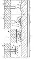
- portions 1 to 4 of the figure illustrate four sequential steps in the application of a female creasing die to a platen F. All four portions of the figure illustrate the application process in cross-section, it being understood that the female creasing die is in fact an elongate strip member D having two elongate channels G on the upper surface thereof. On the under surface of the strip D an adhesive is provided for securing the strip D to the platen F.
- a movable press member B provided with two parallel and closely spaced creasing rules A. It will be seen that the creasing rules A are positioned to cooperate with respective ones of the channels G provided in the female die strip D.
- a locator member E On the upper surface of the die strip D, is provided a locator member E.
- This member E has a central upstanding rib H and two side portions C which engage around the edges of the die strip D. This peripheral engagement of edges C with the die strip D maintains the member E and the die strip D in removable engagement. It will be observed that upstanding rib H is dimensioned to engage by friction fit between the two creasing rules A so that the combination of die strip D and locator member E can be suspended from the creasing rules A by means of this friction fit.
- the method of securing the die strip D to the platen F is as follows. First referring to portion 1 of the figure, the die strip and locator member combination is positioned on the creasing rules A, the rib H engaging by friction fit between the creasing rules A. As shown in portion 2 of the figure, the movable press member B is lowered towards the platen F thus bringing the surface of die strip D into contact with the platen F, where it is secured by means of the adhesive. As shown in portion 3 of the Figure, the movable press member B is then raised away from the die strip D leaving the die strip D and the locator member E in a position on the platen F.
- the locator member E may then be stripped away from the die strip D leaving the arrangement as shown in portion 4 of the figure with the die strip D in readiness for cooperation with the creasing rules A to produce two closely spaced and parallel creases in a piece of cardboard or paperboard or the like.
- Locator strip E is preferably made of a synthetic plastics material.
- the method and apparatus may be applied to the production of, for example, record sleeves where the spine of the record sleeve requires two closely spaced parallel creases for its production.
- the female die strip D is preferably formed of three upstanding members of synthetic plastics material (between which channels G are defined) mounted on a thin metal backing plate on which the adhesive layer is provided.
- the plastics members can be manufactured by an extrusion process.
- the distance between the centre lines of channels G may be less than 7 mm, for example between 3 mm and 5 mm. It is envisaged that double channel die strips of'three standard gauges will be produced, having respectively 3 mm, 4 mm and 5 mm centre line spacing.
- the locator member E has a single upstanding rib H for frictional engagement between creasing rules A, this is not essential.
- member E may have a single narrow upstanding rib in which is provided an elongate groove for receiving one of the creasing rules A.
- the member E may have no upstanding member but have instead two elongate grooves in its surface spaced for receiving respective creasing rules A for frictional engagement therewith.
- a further alternative is for the member E to provide two lateral upstanding members for frictional engagement with the outer surfaces of respective creasing rules A with no engagement between rules A.
- the illustrated embodiment is however the simplest and most reliable from a manufacturing stand point.
Landscapes
- Engineering & Computer Science (AREA)
- Mechanical Engineering (AREA)
- Life Sciences & Earth Sciences (AREA)
- Forests & Forestry (AREA)
- Making Paper Articles (AREA)
- Folding Of Thin Sheet-Like Materials, Special Discharging Devices, And Others (AREA)
- Machines For Manufacturing Corrugated Board In Mechanical Paper-Making Processes (AREA)
Abstract
A female creasing die strip D is provided with two channels G for cooperation with two creasing rules A. To affix die D to platen F, a location device E is provided on die D and has means H for frictional engagement with at least one of rules A at a position in which rules A are accurately aligned with channels G. Adhesive on die strip D causes adhesion of die strip D to platen F whereafter device E pulls free from rules A. Device E is then removed from die strip D before creasing operation begins.
Description
- The present invention relates to a female creasing die comprising a strip member provided with adhesive on one side and a channel on its other side. The invention also relates to apparatus for creasing including such a creasing die.
- Creasing of cardboard, paperboard and'like materials for manufacturing cartons or boxes is normally achieved by the use of a press having a platen on which is provided a channel creasing matrix forming a so-called makeready as shown, for example, in U.K. Patent No. 807,251. The channel creasing matrix on the platen defines a number of channels which cooperate with so-called creasing rules provided on the movable plate of the press, which creasing rules are arranged to descend into the channels, thus creasing any cardboard or paperboard which is positioned on the platen along lines defined by the position of the channels. It is clearly important to ensure that the matrix of channels on the platen is accurately aligned with the position of the creasing rules on the descending plate. This is best achieved in a preliminary makeready producing operation in which the channel creasing matrix is engaged with the creasing rules and is provided with an adhesive on its lower surface. The press is then put on impression, and after completing one cycle the channel matrix adheres to the platen and pulls free from the creasing rules. In order that the creasing matrix may be attached to the creasing rules to allow this cycle of operations to take place, the upper surface of the channel matrix is provided with a locator strip having a groove which fit over the creasing rules. This locator strip can be easily pulled free of the channel matrix after the channel matrix is secured to the platen. Conventionally, the locator strip is provided with a groove defined by two upstanding walls which embrace the creasing rule therebetween and are so held thereon by friction. This arrangement, however, does not readily lend itself to the production of a creasing matrix suitable for placing two creasing channels very close together such as would be required for the production of a record sleeve. In this case, since the creasing rules must also be positioned very close together, there is insufficient room between the two adjacent creasing rules to position two locator strips of the conventional type.
- According to one aspect of the invention, there is provided a female creasing die comprising a strip member provided with adhesive on one side and a channel on its other side characterised in that a further channel is provided on said other side parallel to the other channel and in that a single removable locator member is positioned on said other side and is provided with engagement means arranged for frictional engagement with at least one of two creasing rules spaced for mating with respective ones of said channels.
- Preferably, said engagement means comprises an upstanding rib arranged for frictional engagement with at least one of said creasing rules.
- Preferably, said rib is parallel to and central of said channels and is dimensioned for a friction fit between said creasing rules.
- Preferably, said locator member is provided with. two side portions extending from said rib.
- In one embodiment, said side portions are arranged resiliently to grip edges of said strip member.
- In another embodiment, said locator member is bonded to said strip.
- Said locator member may be attached to said strip by a thermal bond.
- The distance between the centre lines may be less than 7 mm.
- Preferably, said strip comprises three upstanding members of synthetic plastics material mounted on a common metal blocking plate and defining said channels therebetween.
- According to a further aspect of the invention, there is provided apparatus for creasing comprising: a platen; at least one female creasing die mounted on the platen and providing a creasing channel; and a movable press member having at least one creasing rule positioned for mating with a respective creasing channel characterised in that; said die is in accordance with the above-defined female creasing die, and in that the movable press member has two creasing rules positioned for mating with respective channels.
- For a better understanding of the invention, and to show how the same may be carried into effect, reference will now be made, by way of example, to the accompanying drawing, the single figure of which shows four steps in the application of a female creasing die to a platen.
- Referring to the figure in more detail,
portions 1 to 4 of the figure illustrate four sequential steps in the application of a female creasing die to a platen F. All four portions of the figure illustrate the application process in cross-section, it being understood that the female creasing die is in fact an elongate strip member D having two elongate channels G on the upper surface thereof. On the under surface of the strip D an adhesive is provided for securing the strip D to the platen F. In the upper part of each portion of the figure, is illustrated a movable press member B provided with two parallel and closely spaced creasing rules A. It will be seen that the creasing rules A are positioned to cooperate with respective ones of the channels G provided in the female die strip D. On the upper surface of the die strip D, is provided a locator member E. This member E has a central upstanding rib H and two side portions C which engage around the edges of the die strip D. This peripheral engagement of edges C with the die strip D maintains the member E and the die strip D in removable engagement. It will be observed that upstanding rib H is dimensioned to engage by friction fit between the two creasing rules A so that the combination of die strip D and locator member E can be suspended from the creasing rules A by means of this friction fit. - The method of securing the die strip D to the platen F is as follows. First referring to
portion 1 of the figure, the die strip and locator member combination is positioned on the creasing rules A, the rib H engaging by friction fit between the creasing rules A. As shown inportion 2 of the figure, the movable press member B is lowered towards the platen F thus bringing the surface of die strip D into contact with the platen F, where it is secured by means of the adhesive. As shown inportion 3 of the Figure, the movable press member B is then raised away from the die strip D leaving the die strip D and the locator member E in a position on the platen F. The locator member E may then be stripped away from the die strip D leaving the arrangement as shown inportion 4 of the figure with the die strip D in readiness for cooperation with the creasing rules A to produce two closely spaced and parallel creases in a piece of cardboard or paperboard or the like. - It will be apparent that, within the scope of the invention, various methods may be utilised for securing the locator member E to the die strip D. The side portions C of the member E are not essential, it being possible to secure the rib H to the die strip D by, for example, a thermal bond. The preferred method, however, is as illustrated where the side portions E resiliently grip the edges of the die strip D and positively locate the rib H in the correct position.
- Locator strip E is preferably made of a synthetic plastics material.
- By use of the described apparatus and method, it is possible to crease cardboard or paperboard with two parallel and closely spaced creases without any great expense or difficulty. The method and apparatus may be applied to the production of, for example, record sleeves where the spine of the record sleeve requires two closely spaced parallel creases for its production.
- The female die strip D is preferably formed of three upstanding members of synthetic plastics material (between which channels G are defined) mounted on a thin metal backing plate on which the adhesive layer is provided. The plastics members can be manufactured by an extrusion process.
- The distance between the centre lines of channels G may be less than 7 mm, for example between 3 mm and 5 mm. It is envisaged that double channel die strips of'three standard gauges will be produced, having respectively 3 mm, 4 mm and 5 mm centre line spacing.
- Although it is preferred, as illustrated, that the locator member E has a single upstanding rib H for frictional engagement between creasing rules A, this is not essential. Within the scope of the invention, alternative forms of frictional engagement are possible. For example, member E may have a single narrow upstanding rib in which is provided an elongate groove for receiving one of the creasing rules A. Alternatively, the member E may have no upstanding member but have instead two elongate grooves in its surface spaced for receiving respective creasing rules A for frictional engagement therewith. A further alternative is for the member E to provide two lateral upstanding members for frictional engagement with the outer surfaces of respective creasing rules A with no engagement between rules A.
- The illustrated embodiment is however the simplest and most reliable from a manufacturing stand point.
- By use of the illustrated creasing apparatus, two creases having a centre to centre spacing of a little as 3 mm can be formed in cardboard or paperboard or the like. This has hitherto not been possible with apparatus of this type. Significant production advantages may be achieved in the manufacture of articles such as record sleeves or other articles having two creases very close together, as in the spine of folders and small booklet covers.
Claims (10)
1. A female creasing die comprising a strip member (D) provided with adhesive on one side and a channel (G) on its other side characterised in that a further channel (G) is provided on said other side parallel to the other channel (G) and in that a single removable locator member (E) is positioned on said other side and is provided with engagement means (H) arranged for frictional engagement with at least one of two creasing rules (A) spaced for mating with respective ones of said channels (G).
2. A die according to claim 1 characterised in that said engagement means comprises an upstanding rib (H) arranged for frictional engagement with at least one of said creasing rules (A).
3. A die according to claim 2 characterised in that said rib (H) is parallel to and central of said channels (G) and is dimensioned for a friction fit between said creasing rules (A).
4. A die according to claim 2 or 3 characterised in that said locator member (E) is provided with two side portions (C) extending from said rib (H).
5. A die according to claim 4 characterised in that said side portions (C) are arranged resiliently to grip edges of said strip member (D).
6. A die according to any.one of claims 1 to 4 characterised in that said locator member (E) is bonded to said strip (D).
7. A die according to claim 6 characterised in that said locator member (E) is attached to said strip (D) by a thermal bond.
8. A die according to any one of the preceding claims characterised in that the distance between the centre lines of said channels (G) is less than 7 mm.
9. A die according to any one of the preceding claims characterised in that said strip (D) comprises three upstanding members of synthetic plastics material mounted on a common metal backing place and defining said channels (G) therebetween.
10. Apparatus for creasing comprising: a platen (F) at least one female creasing die mounted on the platen and providing a creasing channel; and a movable press member (B) having at least one creasing rule (A) positioned for mating with a creasing channel (G) characterised in that: said die is in accordance with any one of claims 1 to 9, and in that the movable press member (B) has two creasing rules (A) positioned for mating with respective channels (G).
Applications Claiming Priority (2)
| Application Number | Priority Date | Filing Date | Title |
|---|---|---|---|
| GB7926663 | 1979-07-31 | ||
| GB7926663 | 1979-07-31 |
Publications (2)
| Publication Number | Publication Date |
|---|---|
| EP0023815A2 true EP0023815A2 (en) | 1981-02-11 |
| EP0023815A3 EP0023815A3 (en) | 1981-02-18 |
Family
ID=10506897
Family Applications (1)
| Application Number | Title | Priority Date | Filing Date |
|---|---|---|---|
| EP80302591A Withdrawn EP0023815A3 (en) | 1979-07-31 | 1980-07-30 | Apparatus and methods for use in creasing cardboard and like materials |
Country Status (1)
| Country | Link |
|---|---|
| EP (1) | EP0023815A3 (en) |
Cited By (1)
| Publication number | Priority date | Publication date | Assignee | Title |
|---|---|---|---|---|
| EP1502729A1 (en) * | 2003-07-30 | 2005-02-02 | Cito-System GmbH | Method for manufacturing of a matrix strip for creasing carton blanks |
Citations (2)
| Publication number | Priority date | Publication date | Assignee | Title |
|---|---|---|---|---|
| GB807251A (en) * | 1956-11-12 | 1959-01-14 | Squire Harold Frederick | Improvements in or relating to creasing devices for the production of boxes, cartonsand folders |
| GB966630A (en) * | 1962-04-30 | 1964-08-12 | Container Corp | Method of preparing scoring dies |
-
1980
- 1980-07-30 EP EP80302591A patent/EP0023815A3/en not_active Withdrawn
Patent Citations (2)
| Publication number | Priority date | Publication date | Assignee | Title |
|---|---|---|---|---|
| GB807251A (en) * | 1956-11-12 | 1959-01-14 | Squire Harold Frederick | Improvements in or relating to creasing devices for the production of boxes, cartonsand folders |
| GB966630A (en) * | 1962-04-30 | 1964-08-12 | Container Corp | Method of preparing scoring dies |
Cited By (1)
| Publication number | Priority date | Publication date | Assignee | Title |
|---|---|---|---|---|
| EP1502729A1 (en) * | 2003-07-30 | 2005-02-02 | Cito-System GmbH | Method for manufacturing of a matrix strip for creasing carton blanks |
Also Published As
| Publication number | Publication date |
|---|---|
| EP0023815A3 (en) | 1981-02-18 |
Similar Documents
| Publication | Publication Date | Title |
|---|---|---|
| US3884132A (en) | Magnetically located scoring die matrix | |
| US4112827A (en) | Method of making cutting, scoring and embossing die set | |
| SE413647B (en) | PROCEDURE AND DEVICE FOR PREPARING A PERM, A COPY OR SIMILAR | |
| GB1472304A (en) | Multi-layer composite and method of making same and articles therefrom | |
| US3745055A (en) | Assembly for making a paper board sound recording package | |
| US5414991A (en) | Paper staples and a process for the production thereof | |
| CA2165703A1 (en) | Separation Method for Adhesive Sheet and Its Device | |
| US3064511A (en) | Method for rapid mounting of tool sets | |
| EP0023815A2 (en) | Apparatus and methods for use in creasing cardboard and like materials | |
| US4195557A (en) | Cutting, scoring and embossing die set | |
| JPH0948077A (en) | Grooving form for stamping rule and ruler for stamping rule | |
| US1365291A (en) | Shim and method of making the same | |
| ES548754A0 (en) | A METHOD FOR MANUFACTURING AN ALUMINUM SHEET WITH A THICKNESS LESS THAN 50 MICROMETERS. | |
| US3054172A (en) | Method of making serialized nameplates | |
| US2321740A (en) | Article and a method of mounting characters of wood, or the like, on a background of wood, or similar materials | |
| US2467242A (en) | Means for reproducing diagrams, designs, and the like | |
| US2217773A (en) | Manufacture of covers for books or the like | |
| GB2062576A (en) | Label and methods for making it | |
| JP2004268464A (en) | Embossing device and embossing method | |
| SU1003976A1 (en) | Method of separating sheet articles stack | |
| JPS5940202Y2 (en) | Groove forming body for marking | |
| US1892478A (en) | Means for fabricating metallic labels | |
| US2265506A (en) | Carrier and fastening device for papers or the like, and method of making the same | |
| JPS5943750B2 (en) | Label manufacturing method | |
| JPS58167035A (en) | Marking method of sheet metallic part |
Legal Events
| Date | Code | Title | Description |
|---|---|---|---|
| PUAI | Public reference made under article 153(3) epc to a published international application that has entered the european phase |
Free format text: ORIGINAL CODE: 0009012 |
|
| PUAL | Search report despatched |
Free format text: ORIGINAL CODE: 0009013 |
|
| AK | Designated contracting states |
Designated state(s): DE FR GB IT |
|
| AK | Designated contracting states |
Designated state(s): DE FR GB IT |
|
| 17P | Request for examination filed |
Effective date: 19810518 |
|
| STAA | Information on the status of an ep patent application or granted ep patent |
Free format text: STATUS: THE APPLICATION IS DEEMED TO BE WITHDRAWN |
|
| 18D | Application deemed to be withdrawn |
Effective date: 19821029 |