EP0023066B1 - Method of manufacturing light conducting fibres - Google Patents
Method of manufacturing light conducting fibres Download PDFInfo
- Publication number
- EP0023066B1 EP0023066B1 EP80200683A EP80200683A EP0023066B1 EP 0023066 B1 EP0023066 B1 EP 0023066B1 EP 80200683 A EP80200683 A EP 80200683A EP 80200683 A EP80200683 A EP 80200683A EP 0023066 B1 EP0023066 B1 EP 0023066B1
- Authority
- EP
- European Patent Office
- Prior art keywords
- tube
- deposition
- quartz glass
- inside diameter
- value
- Prior art date
- Legal status (The legal status is an assumption and is not a legal conclusion. Google has not performed a legal analysis and makes no representation as to the accuracy of the status listed.)
- Expired
Links
Images
Classifications
-
- C—CHEMISTRY; METALLURGY
- C03—GLASS; MINERAL OR SLAG WOOL
- C03B—MANUFACTURE, SHAPING, OR SUPPLEMENTARY PROCESSES
- C03B37/00—Manufacture or treatment of flakes, fibres, or filaments from softened glass, minerals, or slags
- C03B37/01—Manufacture of glass fibres or filaments
- C03B37/012—Manufacture of preforms for drawing fibres or filaments
- C03B37/014—Manufacture of preforms for drawing fibres or filaments made entirely or partially by chemical means, e.g. vapour phase deposition of bulk porous glass either by outside vapour deposition [OVD], or by outside vapour phase oxidation [OVPO] or by vapour axial deposition [VAD]
- C03B37/018—Manufacture of preforms for drawing fibres or filaments made entirely or partially by chemical means, e.g. vapour phase deposition of bulk porous glass either by outside vapour deposition [OVD], or by outside vapour phase oxidation [OVPO] or by vapour axial deposition [VAD] by glass deposition on a glass substrate, e.g. by inside-, modified-, plasma-, or plasma modified- chemical vapour deposition [ICVD, MCVD, PCVD, PMCVD], i.e. by thin layer coating on the inside or outside of a glass tube or on a glass rod
- C03B37/01861—Means for changing or stabilising the diameter or form of tubes or rods
-
- C—CHEMISTRY; METALLURGY
- C03—GLASS; MINERAL OR SLAG WOOL
- C03B—MANUFACTURE, SHAPING, OR SUPPLEMENTARY PROCESSES
- C03B37/00—Manufacture or treatment of flakes, fibres, or filaments from softened glass, minerals, or slags
- C03B37/01—Manufacture of glass fibres or filaments
- C03B37/012—Manufacture of preforms for drawing fibres or filaments
- C03B37/014—Manufacture of preforms for drawing fibres or filaments made entirely or partially by chemical means, e.g. vapour phase deposition of bulk porous glass either by outside vapour deposition [OVD], or by outside vapour phase oxidation [OVPO] or by vapour axial deposition [VAD]
- C03B37/018—Manufacture of preforms for drawing fibres or filaments made entirely or partially by chemical means, e.g. vapour phase deposition of bulk porous glass either by outside vapour deposition [OVD], or by outside vapour phase oxidation [OVPO] or by vapour axial deposition [VAD] by glass deposition on a glass substrate, e.g. by inside-, modified-, plasma-, or plasma modified- chemical vapour deposition [ICVD, MCVD, PCVD, PMCVD], i.e. by thin layer coating on the inside or outside of a glass tube or on a glass rod
- C03B37/01807—Reactant delivery systems, e.g. reactant deposition burners
- C03B37/01815—Reactant deposition burners or deposition heating means
- C03B37/01823—Plasma deposition burners or heating means
- C03B37/0183—Plasma deposition burners or heating means for plasma within a tube substrate
Definitions
- the invention relates to a process for the production of preforms for the production of optical fibers, wherein quartz glass with any doping by reactive deposition from the gas phase under the action of a non-isothermal plasma is attached to the inside of a quartz glass tube and the internally coated tube collapses to form a solid preform.
- the optical fiber produced therefrom can consist of a core made of doped quartz glass and a jacket made of quartz glass or of a core made of undoped or doped quartz and a first jacket made of doped quartz glass and an outer jacket made of quartz glass.
- DE-C-2 444100 describes a method by which internally coated glass tubes for drawing optical fibers are produced.
- a non-isothermal plasma is used at a pressure of approximately 1.3 to 13 mbar.
- the inside diameter of the tube at the end of the coating should be as small as possible in order to enable a geometrically perfect collapse.
- the object of the invention is therefore to provide a method with which an increased deposition rate is achieved using a non-isothermal plasma without disturbing fine glass particles occurring in the gas phase, the inside diameter of the tube being as small as possible after the coating process, to ensure problem-free collapse.
- the deposition rate M is greater than 0.08 g / min and is set such that during the coating
- the preform thus produced is drawn into a fiber in a manner known per se.
- the starting pipe to be coated and the thickness of the layer to be deposited should be chosen so that the subsequent collapsing step does not pose any additional problems.
- the inner diameter of the tube should be as small as possible at the end of the deposition process before collapsing, because each additional mm increases the risk of errors in the collapse, such as the formation of an elliptical preform, one that is bent over its length Preform or other geometric error.
- the rotational symmetry of the coated tube can best be maintained if the collapse step is as small as possible.
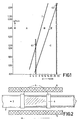
- Limits G1 and G2 are also shown in FIG. 1. Below about 6 mm inner tube diameter, the achievable deposition rates are so low that they become economically uninteresting; with an inner diameter of over 30 mm, the coated tube is very difficult to collapse into a solid, bubble-free, cylindrical preform.
- the equations given are particularly important if, in order to shorten the collapse step, a layer as thick as possible is applied to the inside of the tube. Since the inner diameter of the tube then becomes smaller and smaller, the deposition speed must also be adjusted accordingly. You can then start with a high deposition speed, but you have to reduce it continuously as the inside diameter decreases. You should always stay in area B if possible.
- the temperature of the substrate tube in the experiments was in the range from about 1000 ° C to 12000 ° C. Even at the high deposition rates, an almost complete yield is obtained, ie the entire SiC1 4 fed into the tube together with any dopant in the form of a halide is converted into Si0 2 using the oxygen in the region of the microwave discharge and the dopant in the form of an oxide converted. It is therefore easy to determine the necessary and sufficient halide (SiCl 4 + dopant in the form of the halide) gas flow for any desired deposition rate.
- the oxygen flow results from the fact that the total pressure in the reaction zone is preferably in the range from 1 to 27 mbar and that the stoichiometric flow of oxygen must be at least as great as the halide flow. A triple or larger surplus has turned out to be favorable.
- GeC) 4 , BCI 3 , SiF 4 , PCI 3 and other known dopants can be used as dopants in the form of the halide.
- the plasma is necessary for the activation of the reaction and, with a larger number of molecules to be activated per unit of time, it also requires a greater power supply. If the microwave power is too low, this becomes apparent through the deposition of opaque layers. In practice, the required power is determined by increasing the supplied microwave power in a preliminary test until the layers are deposited crystal-clear.
- the microwave power supplied is at least so great that the diameter of the tube is completely filled with the plasma.
- a rotationally symmetrical energy density in the tube is required for a rotationally symmetrical deposition profile. If the conditions mentioned here are met, it is found that the deposited layers are of fiber-optic quality, regardless of the deposition rate.
- the electron temperature is equal to the gas temperature. Both are typically in the order of tens of thousands of degrees.
- the electron temperature is considerably higher than the gas temperature.
- the electron temperature typically has values of some 10,000 K, the gas The temperature typically increases - depending on the gas type and pressure - by a maximum of a few 100 K.
- FIG. 2 shows the deposition of Si0 2 glass 1 from a gas mixture SiCl 4 / O 2 and any dopant in the form of a halide 2 on the inner wall of a quartz glass tube 3.
- the gas mixture 2 is passed through the pipe 3 in the direction of the arrow.
- a local non-isothermal plasma 4 is generated by ring electrodes 5 and either inductively or capacitively coupled, or generated in a microwave resonator.
- the arrow drawn below the device indicates a relative movement between the tube 3 and the plasma-exciting device in the axial direction.
- the plasma 4 is overlaid by a furnace 6, a temperature zone that exceeds the plasma range.
- the inside of a quartz glass tube was coated with quartz glass which was doped with Ge0 2 and B 2 0 3 .
- the microwave frequency used was 2.45 GHz, the speed of the reaction zone was 3 m / min and the length of the deposition area was 35 cm.
- the substrate temperature was 1050 ° C, the total pressure was 13 mbar.
- the microwave power was 200 W.
- the quartz tube used had an inner diameter of 6 mm and an outer diameter of 8 mm.
- the SiCl 4 flow was 30 cm 3 / min (based on standard conditions, temperature 0 ° C, pressure 1 bar - this also applies to the following information of this type), the GeCl 4 flow became linear with the time until the end of the experiment increased from 0 cm 3 / min to 4 cm 3 / min.
- the O 2 flow was 150 cm 3 / min and the BCI 3 flow was 3 cm 3 / min.
- the deposition rate was 0.08 g / min. This deposition rate was already at the critical limit. A further increase in the deposition rate led to the formation of fine glass particles in the gas phase.
- Example 1 Compared to Example 1, the following conditions were changed: the inside diameter of 8 mm, the outside diameter of 10 mm, the SiC1 4 flow, which here was 60 cm 3 / min, the CeCl 4 flow, which went from 0 to 7.5 cm 3 / min was increased, the BCI 3 flow with 5 cm 3 / min and the total pressure with 20 mbar.
- the deposition rate was 0.15 g / min.
- a microwave power of 500 W was used.
- the quartz glass tube used had an inner diameter of 11.5 mm and an outer diameter of 14 mm.
- the SiCl 4 flow was initially 132 cm 3 / min and was linearly reduced to 116 cm 3 / min at the time t o .
- the BCI 3 flow was initially 21 cm 3 / min and was gradually reduced to 7.5 cm 3 / min.
- the GeCI 4 current was increased linearly with the time from 0 cm 3 / min to the final value of 16 cm 3 / min.
- the oxygen flow was 500 cm 3 / min and rose linearly from time to 595 cm3 / min.
- the average deposition rate was 0.3 g / min.
- the substrate temperature was 1050 ° C, the pressure in the reaction zone was 13 mbar.
- the method described can be used both for the deposition of doped and undoped quartz glass, specifically for the production of monomode and multimode fibers.
- the doping can be kept constant during the deposition (step index fiber), or can also increase or decrease (gradient fiber).
Abstract
Description
Die Erfindung betrifft ein Verfahren zur Herstellung von Vorformen für die Herstellung von Lichtleitfasern, wobei Quarzglas mit einer etwaigen Dotierung durch reaktive Abscheidung aus der Gasphase unter Einwirkung eines nichtisothermen Plasmas auf der Innenseite eines Quarzglasrohres angebracht wird und das innenbeschichtete Rohr zu einer massiven Vorform kollabiert.The invention relates to a process for the production of preforms for the production of optical fibers, wherein quartz glass with any doping by reactive deposition from the gas phase under the action of a non-isothermal plasma is attached to the inside of a quartz glass tube and the internally coated tube collapses to form a solid preform.
Die daraus hergestellte Lichtleitfaser kann aus einem Kern aus dotiertem Quarzglas und einem Mantel aus Quarzglas bestehen oder aus einem Kern aus nicht dotiertem oder dotiertem Quarz und einem ersten Mantel aus dotiertem Quarzglas und einem äusseren Mantel aus Quarzglas bestehen.The optical fiber produced therefrom can consist of a core made of doped quartz glass and a jacket made of quartz glass or of a core made of undoped or doped quartz and a first jacket made of doped quartz glass and an outer jacket made of quartz glass.
In der DE-C-2 444100 ist ein Verfahren beschrieben, nach welchem innenbeschichtete Glasrohre zum Ziehen von Lichtleitfasern hergestellt werden. Dabei wird ein nichtisothermes Plasma bei einem Druck von etwa 1,3 bis 13 mbar angewendet. Um gute, spannungsfreie Schichten zu erzeugen, ist es notwendig, das als Substrat dienende Glasrohr durch eine überlagerte Temperaturzone zu erhitzen. Bei diesem Verfahren werden direkt aus der Glasphase glasige Schichten gebildet. Es treten dabei normalerweise keine Glaspartikel auf.DE-C-2 444100 describes a method by which internally coated glass tubes for drawing optical fibers are produced. A non-isothermal plasma is used at a pressure of approximately 1.3 to 13 mbar. In order to produce good, stress-free layers, it is necessary to heat the glass tube serving as the substrate through a superimposed temperature zone. In this process, glassy layers are formed directly from the glass phase. There are usually no glass particles.
Nach J. Electrochem. Soc. 125 (1978) 1298-1302 werden mit dem plasmaaktivierten CVD-Verfahren hochtransparente, dicke, mit Fluor dotierte Quarzglasschichten erhalten. Die Quarzglasschichten werden auf der Innenseite eines Quarzglasrohres abgeschieden, das einen Innendurchmesser von 8 mm hat. Aus den in diesem Dokument angegebenen Durchflussraten von SiCI4 und SiF4 lässt sich errechnen, dass die Abscheidungsgeschwindigkeit zwischen 0,02 und 0,08 g/min liegt.After J. Electrochem. Soc. 125 (1978) 1298-1302 are obtained with the plasma-activated CVD process, highly transparent, thick, fluorine-doped quartz glass layers. The quartz glass layers are deposited on the inside of a quartz glass tube that has an inner diameter of 8 mm. It can be calculated from the flow rates of SiCI 4 and SiF 4 given in this document that the deposition rate is between 0.02 and 0.08 g / min.
Bei den Untersuchungen, die zur Erfindung geführt haben, hat es sich gezeigt, dass bei dem zuvor erwähnten Plasmaverfahren gegebenenfalls dann feine Glaspartikel gebildet werden können, wenn die Reaktionsbedingungen geändert werden. Solche Partikel sind aber mit dem in der DE-C-2 444100 beschriebenen Verfahren absolut unvereinbar und müssen deshalb unter allen Umständen vermieden werden, weil es sich herausgestellt hat, dass diese Partikel sich bei diesem Verfahren nicht zu glasigen Schichten einschmelzen lassen, ohne dass auch das Rohr dabei schmilzt. Insbesondere Versuche, die Abscheidungsgeschwindigkeit zu erhöhen, können zu der Bildung dieser unerwünschten Glaspartikel führen.In the investigations that led to the invention, it has been shown that fine glass particles can be formed in the aforementioned plasma process if the reaction conditions are changed. However, such particles are absolutely incompatible with the process described in DE-C-2 444100 and must therefore be avoided under all circumstances, because it has been found that this process does not allow these particles to be melted into glassy layers without it the pipe melts. In particular, attempts to increase the deposition rate can lead to the formation of these undesirable glass particles.
Ferner hat es sich gezeigt, dass bei fest vorgegebener Abscheidungsgeschwindigkeit der Innendurchmesser des Rohres am Ende der Beschichtung möglichst klein sein soll, um ein geometrisch einwandfreies Kollabieren zu ermöglichen.Furthermore, it has been shown that, given a fixed deposition speed, the inside diameter of the tube at the end of the coating should be as small as possible in order to enable a geometrically perfect collapse.
Die Aufgabe der Erfindung besteht demnach darin, ein Verfahren zu schaffen, mit dem unter Anwendung eines nichtisothermen Plasmas eine erhöhte Abscheidungsgeschwindigkeit erzielt wird, ohne dass störende feine Glaspartikel in der Gasphase auftreten, wobei der Innendurchmesser des Rohres nach dem Beschichtungsprozess so klein wie möglich ist, um eine problemlose Kollabiering zu gewährleisten.The object of the invention is therefore to provide a method with which an increased deposition rate is achieved using a non-isothermal plasma without disturbing fine glass particles occurring in the gas phase, the inside diameter of the tube being as small as possible after the coating process, to ensure problem-free collapse.
Diese Aufgabe wird erfindungsgemäss dadurch gelöst, dass die Abscheidungsgeschwindigkeit M grösser als 0,08 g/min ist und so eingestellt wird, dass während der BeschichtungThis object is achieved according to the invention in that the deposition rate M is greater than 0.08 g / min and is set such that during the coating

Bei den Versuchen, die zur Erfindung geführt haben, hat es sich gezeigt, dass dieser überraschend einfache Zusammenhang zwischen dem Rohrinnendurchmesser während der Abscheidung und der maximalen Abscheidungsgeschwindigkeit, bei der noch keine feinen Glaspartikel in der Gasphase auftreten, besteht. Der Wert für A wurde dabei experimentell festgestellt.In the tests that led to the invention, it has been shown that there is this surprisingly simple relationship between the inside diameter of the tube during the deposition and the maximum deposition rate at which no fine glass particles still occur in the gas phase. The value for A was determined experimentally.
Es hat sich weiter gezeigt, dass ein geometrisch einwandfreies Kollabieren der nach der Erfindung beschichteten Quarzglasrohre immer dann gesichert ist, wenn die Abscheidung so lange fortgesetzt wird, bis der Innendurchmesser d"
wobei M denselben Wert wie zuvor besitzt und A" den Wert 6,63 · 10-5 g/min besitzt.where M has the same value as before and A "has the value 6.63 · 10- 5 g / min.
Die so hergestellte Vorform wird in an sich bekannter Weise zu einer Faser ausgezogen.The preform thus produced is drawn into a fiber in a manner known per se.
Die Erfindung wird anhand einer Zeichnung und mit einigen Ausführungsbeispielen näher erläutert.The invention is explained in more detail with reference to a drawing and with some exemplary embodiments.
In der Zeichnung zeigen
- Fig. 1 den Zusammenhang zwischen abgeschiedener Quarzglasmenge und Rohrinnendurchmesser in Form eines Schaubildes und
- Fig. eine Vorrichtung zum Innenbeschichten von Glasrohren in schematischer Darstellung.
- Fig. 1 shows the relationship between the amount of quartz glass deposited and the inner tube diameter in the form of a graph and
- Fig. A device for the inner coating of glass tubes in a schematic representation.
In Fig. 1 ist die gemäss der Reaktionsgleichung
![]()
![]()
Die Grenzgerade I wird beschrieben durch
Ein weiterer wichtiger Gesichtspunkt ist die Beachtung des nachfolgenden Kollabierungsprozesses. Das zu beschichtende Ausgangsrohr und die Dicke der abzuscheidenden Schicht sollten so gewählt werden, dass der nachfolgende Kollabierungsschritt keine zusätzlichen Probleme aufwirft. Ganz allgemein kann man sagen, dass der Innendurchmesser des Rohres am Ende des Abscheidungsvorgangs vor dem Kollabieren so klein wie möglich sein sollte, denn jeder zusätzliche mm erhöht die Gefahr, dass Fehler beim Kollabieren auftreten, wie Entstehen einer elliptischen Vorform, einer über die Länge durchgebogenen Vorform oder anderer geometrischer Fehler. Die Rotationssymmetrie des beschichteten Rohres kann am besten gewahrt werden, wenn der Kollabierungsschritt möglichst klein ist.Another important aspect is the consideration of the subsequent collapse process. The starting pipe to be coated and the thickness of the layer to be deposited should be chosen so that the subsequent collapsing step does not pose any additional problems. In general it can be said that the inner diameter of the tube should be as small as possible at the end of the deposition process before collapsing, because each additional mm increases the risk of errors in the collapse, such as the formation of an elliptical preform, one that is bent over its length Preform or other geometric error. The rotational symmetry of the coated tube can best be maintained if the collapse step is as small as possible.
Aus dem Gesagten folgt, dass der Innendurchmesser des zu kollabierenden Rohres möglichst klein sein sollte. Diese Forderung muss aber obige Gleichung für d, beachten, die eine untere Grenze für den Innendurchmesser beim Beschichten angibt. Es hat sich nun bei Experimenten gezeigt, dass der Bereich B alle diese Forderungen gut erfüllt. Dabei ist zu berücksichtigen, dass das Rohr während der Beschichtung seinen Innendurchmesser verringert und der Endpunkt unterhalb der Geraden d, liegen sollte. Die Grenze II ist durch folgenden Ausdruck gegeben:
Ferner sind in Fig. 1 die Begrenzungen G1 und G2 eingezeichnet. Unterhalb von etwa 6 mm Rohrinnendurchmesser sind nämlich die erreichbaren Abscheidungsgeschwindigkeiten so gering, dass sie ökonomisch uninteressant werden; bei einem Innendurchmesser von über 30 mm lässt sich das beschichtete Rohr nur sehr schwierig zu einer massiven, blasenfreien, zylindrischen Vorform kollabieren. Die angegebenen Gleichungen sind besonders dann wichtig, wenn man, um den Kollabierungsschrittzu verkürzen, eine möglichst dicke Schicht auf der Innenseite des Rohres anbringt. Da dann der Innendurchmesser des Rohres laufend kleiner wird, muss man auch die Abscheidungsgeschwindigkeit entsprechend anpassen. Man kann dann zunächst mit einer hohen Abscheidungsgeschwindigkeit beginnen, muss sie dann aber laufend reduzieren, wenn sich der Innendurchmesser verkleinert. Man sollte dabei möglichst immer im Bereich B bleiben.Limits G1 and G2 are also shown in FIG. 1. Below about 6 mm inner tube diameter, the achievable deposition rates are so low that they become economically uninteresting; with an inner diameter of over 30 mm, the coated tube is very difficult to collapse into a solid, bubble-free, cylindrical preform. The equations given are particularly important if, in order to shorten the collapse step, a layer as thick as possible is applied to the inside of the tube. Since the inner diameter of the tube then becomes smaller and smaller, the deposition speed must also be adjusted accordingly. You can then start with a high deposition speed, but you have to reduce it continuously as the inside diameter decreases. You should always stay in area B if possible.
Die Temperatur des Substratrohres befand sich bei den Experimenten im Bereich von etwa 1000 °C bis 12000 °C. Auch bei den hohen Abscheidungsgeschwindigkeiten erhält man eine nahezu vollständige Ausbeute, d.h. das gesamte in das Rohr eingespeiste SiC14 zusammen mit dem etwaigen Dotiermittel in Form eines Halogenids wird mit Hilfe des Sauerstoffs im Bereich der Mikrowellenentladung in Si02 und das Dotiermittel in die Form eines Oxids umgewandelt. Deshalb kann man den zu jeder gewünschten Abscheidungsgeschwindigkeit notwendigen und hinreichenden Halogenid- (SiCl4 + Dotiermittel in Form des Halogenids) Gasstrom einfach bestimmen. Der Sauerstoffstrom ergibt sich daraus, dass der Gesamtdruck in der Reaktionszone vorzugsweise im Bereich von 1 bis 27 mbar liegt, und dass der Sauerstoffstrom aus stöchiometrischen Gründen mindestens so gross wie der Halogenid-Strom sein muss. Ein dreifacher oder grösserer Überschuss hat sich als günstig herausgestellt. Als Dotiermittel in Form des Halogenids können z.B. GeC)4, BCI3, SiF4, PCI3 und andere bekannte Dotiermittel verwendet werden.The temperature of the substrate tube in the experiments was in the range from about 1000 ° C to 12000 ° C. Even at the high deposition rates, an almost complete yield is obtained, ie the entire SiC1 4 fed into the tube together with any dopant in the form of a halide is converted into Si0 2 using the oxygen in the region of the microwave discharge and the dopant in the form of an oxide converted. It is therefore easy to determine the necessary and sufficient halide (SiCl 4 + dopant in the form of the halide) gas flow for any desired deposition rate. The oxygen flow results from the fact that the total pressure in the reaction zone is preferably in the range from 1 to 27 mbar and that the stoichiometric flow of oxygen must be at least as great as the halide flow. A triple or larger surplus has turned out to be favorable. For example, GeC) 4 , BCI 3 , SiF 4 , PCI 3 and other known dopants can be used as dopants in the form of the halide.
Das Plasma ist für die Aktivierung der Reaktion notwendig und es benötigt bei einer grösseren Zahl von zu aktivierenden Molekülen pro Zeiteinheit auch eine grössere Leistungszufuhr. Eine zu geringe Mikrowellenleistung macht sich durch die Abscheidung von undurchsichtigen Schichten bemerkbar. In der Praxis stellt man die benötigte Leistung dadurch fest, dass man in einem Vorversuch die zugeführte Mikrowellenleistung so lange erhöht, bis die Schichten glasklar abgeschieden werden.The plasma is necessary for the activation of the reaction and, with a larger number of molecules to be activated per unit of time, it also requires a greater power supply. If the microwave power is too low, this becomes apparent through the deposition of opaque layers. In practice, the required power is determined by increasing the supplied microwave power in a preliminary test until the layers are deposited crystal-clear.
Insbesondere ist darauf zu achten, dass die zugeführte Mikrowellenleistung mindestens so gross ist, dass der Durchmesser des Rohres vollständig mit dem Plasma ausgefüllt ist. Ferner ist eine rotationssymmetrische Energiedichte im Rohr für ein rotationssymmetrisches Abscheidungsprofil erforderlich. Werden die hier genannten Bedingungen erfüllt, so stellt man fest, dass die abgeschiedenen Schichten von faseroptischer Qualität sind, und zwar unabhängig von der Abscheidungsgeschwindigkeit.In particular, care must be taken that the microwave power supplied is at least so great that the diameter of the tube is completely filled with the plasma. Furthermore, a rotationally symmetrical energy density in the tube is required for a rotationally symmetrical deposition profile. If the conditions mentioned here are met, it is found that the deposited layers are of fiber-optic quality, regardless of the deposition rate.
Bei einem isothermen Plasma, auch heisses Plasma genannt, ist die Elektronentemperatur gleich der Gastemperatur. Beide liegen typischerweise in der Grösse von einigen zehntausend Grad. Bei einem nichtisothermen Plasma, auch kaltes Plasma genannt, wie es beim erfindungsgemässen Verfahren angewandt wird, ist die Elektronentemperatur wesentlich höher als die Gastemperatur. Die Elektronentemperatur besitzt typischerweise Werte von einigen 10000 K, die Gastemperatur erhöht sich typischerweise - abhängig von Gasart und Druck - höchstens um einige 100 K.In an isothermal plasma, also called a hot plasma, the electron temperature is equal to the gas temperature. Both are typically in the order of tens of thousands of degrees. In the case of a non-isothermal plasma, also called cold plasma, as is used in the method according to the invention, the electron temperature is considerably higher than the gas temperature. The electron temperature typically has values of some 10,000 K, the gas The temperature typically increases - depending on the gas type and pressure - by a maximum of a few 100 K.
Die nachfolgenden Ausführungsbeispiele wurden in einer Vorrichtung gemäss Fig. 2 durchgeführt. In Fig. 2 ist die Abscheidung von Si02-Glas 1 aus einem Gasgemisch SiCl4/O2 und einem etwaigen Dotiermittel in Form eines Halogenids 2 auf der Innenwandung eines Quarzglasrohres 3 dargestellt. Das Gasgemisch 2 wird in Pfeilrichtung durch das Rohr 3 geleitet. Ein lokales nichtisothermes Plasma 4 wird durch Ringelektroden 5 erzeugt und entweder induktiv oder kapazitiv angekoppelt, oder in einem Mikrowellenresonator erzeugt. Mit dem unterhalb der Vorrichtung eingezeichneten Pfeil ist eine in Achsrichtung erfolgende Relativbewegung zwischen dem Rohr 3 und der plasmaerregenden Vorrichtung angedeutet. Dem Plasma 4 wird mittels eines Ofens 6 eine Temperaturzone überlagert, die den Plasmabereich überschreitet.The following exemplary embodiments were carried out in a device according to FIG. 2. 2 shows the deposition of Si0 2 glass 1 from a gas mixture SiCl 4 / O 2 and any dopant in the form of a
Die Innenseite eines Quarzglasrohres wurde mit Quarzglas beschichtet, das mit Ge02 und B203 dotiert war. Die verwendete Mikrowellenfrequenz betrug 2,45 GHz, die Geschwindigkeit der Reaktionszone betrug 3 m/min, die Länge des Abscheidungsbereiches 35cm. Die Substrattemperatur betrug 1050°C, der Gesamtdruck betrug 13 mbar. Die Mikrowellenleistung war 200 W. Das verwendete Quarzrohr hatte einen Innendurchmesser von 6 mm und einen Aussendurchmesser von 8 mm. Der SiCl4-Strom betrug 30 cm3/min (bezogen auf Standardbedingungen, Temperatur 0°C, Druck 1 bar - dies gilt auch für die folgenden Angaben dieser Art), der GeCl4 Strom wurde linear mit der Zeit bis zum Ende des Versuches von 0 cm3/min auf 4 cm3/min erhöht. der O2-Strom betrug 150 cm3/min und der BCI3-Strom 3 cm3/min. Die Abscheidungsgeschwindigkeit betrug 0,08 g/ min. Diese Abscheidungsgeschwindigkeit lag schon an der kritischen Grenze. Eine weitere Erhöhung der Abscheidungsgeschwindigkeit führte zur Bildung von feinen Glaspartikeln in der Gasphase.The inside of a quartz glass tube was coated with quartz glass which was doped with Ge0 2 and B 2 0 3 . The microwave frequency used was 2.45 GHz, the speed of the reaction zone was 3 m / min and the length of the deposition area was 35 cm. The substrate temperature was 1050 ° C, the total pressure was 13 mbar. The microwave power was 200 W. The quartz tube used had an inner diameter of 6 mm and an outer diameter of 8 mm. The SiCl 4 flow was 30 cm 3 / min (based on standard conditions, temperature 0 ° C,
Gegenüber dem Beispiel 1 wurden folgende Bedingungen geändert: Der Innendurchmesser mit 8 mm, der Aussendurchmesser mit 10 mm, der SiC14-Strom, der hier 60 cm3/min betrug, der CeCl4-Strom, der von 0 auf 7,5 cm3/min erhöht wurde, der BCI3-Strom mit 5 cm3/min und der Gesamtdruck mit 20 mbar. Es ergab sich eine Abscheidungsgeschwindigkeit von 0,15 g/min.Compared to Example 1, the following conditions were changed: the inside diameter of 8 mm, the outside diameter of 10 mm, the SiC1 4 flow, which here was 60 cm 3 / min, the CeCl 4 flow, which went from 0 to 7.5 cm 3 / min was increased, the BCI 3 flow with 5 cm 3 / min and the total pressure with 20 mbar. The deposition rate was 0.15 g / min.
Es wurde mit einer Mikrowellenleistung von 500 W gearbeitet. Das verwendete Quarzglasrohr besass einen Innendurchmesser von 11,5 mm und einen Aussendurchmesser von 14 mm. Der SiCI4-Strom betrug zu Anfang 132 cm3/min und wurde zum Zeitpunkt to linear bis auf 116 cm3/min erniedrigt. Der BCI3-Strom lag zunächst bei 21 cm3/min und wurde allmählich auf 7,5 cm3/min erniedrigt. Der GeCI4-Strom wurde linear mit der Zeit von 0 cm3/min auf den Endwert von 16 cm3/min erhöht. Der Sauerstoffstrom betrug 500 cm3/min und stieg vom Ausganszeitpunkt an linear mit der Zeit auf 595 cm3/min an. Die mittlere Abscheidungsgeschwindigkeit betrug 0,3 g/min. Die Substrattemperatur betrug 1050°C, der Druck in der Reaktionszone lag bei 13 mbar.A microwave power of 500 W was used. The quartz glass tube used had an inner diameter of 11.5 mm and an outer diameter of 14 mm. The SiCl 4 flow was initially 132 cm 3 / min and was linearly reduced to 116 cm 3 / min at the time t o . The BCI 3 flow was initially 21 cm 3 / min and was gradually reduced to 7.5 cm 3 / min. The GeCI 4 current was increased linearly with the time from 0 cm 3 / min to the final value of 16 cm 3 / min. The oxygen flow was 500 cm 3 / min and rose linearly from time to 595 cm3 / min. The average deposition rate was 0.3 g / min. The substrate temperature was 1050 ° C, the pressure in the reaction zone was 13 mbar.
Gegenüber Beispiel 3 wurden verändert:
- Der Innendurchmesser mit 16 mm, der Aussendurchmesser mit 18 mm, der SiCl4-Strom betrug 177 cm3/min, der GeCI4-Strom wurde linear mit der Zeit bis zum Ende des Versuches von 0 cm3f min auf 20 cm3/min erhöht, der BCI3-Strom betrug 10 cm3/min, der Sauerstoffstrom betrug 720 cm3/ min. Die Abscheidungsgeschwindigkeit betrug 0,45 g/min bei einem Gesamtdruck
im Reaktionsrohr von 25 mbar.
- The inside diameter of 16 mm, the outside diameter of 18 mm, the SiCl 4 flow was 177 cm 3 / min, the GeCI 4 flow became linear with the time until the end of the test from 0 cm 3 f min to 20 cm 3 / min increased, the BCI 3 flow was 10 cm 3 / min, the oxygen flow was 720 cm 3 / min. The deposition rate was 0.45 g / min with a total pressure in the reaction tube of 25 mbar.
Nach dem Beschichten wurden alle Rohre kollabiert. Hierzu wird ein Brenner mehrfach längs des beschichteten Quarzrohres hin- und hergefahren. Dabei wird das Rohr lokal auf eine Temperatur von etwa 20000C gebracht, also über den Erweichungspunkt, und schrumpft in mehreren Schritten zu einem Stab (Vorform). Von den so erhaltenen Vorformen wurden Fasern gezogen, die einen Kern von 47pm und einen Aussendurchmesser von 120 µm hatten. Hierzu wird die Vorform mit Hilfe eines Ofens oder eines Ringbrenners auf etwa 2000°C erhitzt. An 1 km langen Faserabschnitten wurden die optischen Daten gemessen. Die optischen Verluste aller Fasern lagen bei der Messwellenlänge von 0,85 µm unter 5 dB/km und die Pulsverbreiterungen waren kleiner als 1,5 ns/ km.After coating, all tubes were collapsed. For this purpose, a burner is moved back and forth several times along the coated quartz tube. The tube is locally brought to a temperature of around 20000C, i.e. above the softening point, and shrinks to a rod (preform) in several steps. Fibers which had a core of 47 μm and an outside diameter of 120 μm were drawn from the preforms thus obtained. To do this, the preform is heated to about 2000 ° C using an oven or a ring burner. The optical data were measured on 1 km long fiber sections. The optical losses of all fibers were below 5 dB / km at the measuring wavelength of 0.85 µm and the pulse broadening was less than 1.5 ns / km.
Das beschriebene Verfahren lässt sich sowohl bei der Abscheidung von dotiertem als von nichtdotiertem Quarzglas anwenden, und zwar bei der Herstellung von Monomoden- und Multimodenfasern. Bei der Abscheidung von dotiertem Quarzglas kann die Dotierung während des Abscheidens konstant gehalten werden (Stufenindexfaser), oder auch zu- oder abnehmen (Gradientenfaser).The method described can be used both for the deposition of doped and undoped quartz glass, specifically for the production of monomode and multimode fibers. When depositing doped quartz glass, the doping can be kept constant during the deposition (step index fiber), or can also increase or decrease (gradient fiber).
Claims (3)


Priority Applications (1)
| Application Number | Priority Date | Filing Date | Title |
|---|---|---|---|
| AT80200683T ATE19388T1 (en) | 1979-07-19 | 1980-07-14 | PROCESS FOR THE MANUFACTURE OF OPTICAL FIBERS. |
Applications Claiming Priority (2)
| Application Number | Priority Date | Filing Date | Title |
|---|---|---|---|
| DE19792929166 DE2929166A1 (en) | 1979-07-19 | 1979-07-19 | METHOD FOR THE PRODUCTION OF OPTICAL FIBERS |
| DE2929166 | 1979-07-19 |
Publications (2)
| Publication Number | Publication Date |
|---|---|
| EP0023066A1 EP0023066A1 (en) | 1981-01-28 |
| EP0023066B1 true EP0023066B1 (en) | 1986-04-23 |
Family
ID=6076114
Family Applications (1)
| Application Number | Title | Priority Date | Filing Date |
|---|---|---|---|
| EP80200683A Expired EP0023066B1 (en) | 1979-07-19 | 1980-07-14 | Method of manufacturing light conducting fibres |
Country Status (9)
| Country | Link |
|---|---|
| US (1) | US4314833A (en) |
| EP (1) | EP0023066B1 (en) |
| JP (1) | JPS5945609B2 (en) |
| AT (1) | ATE19388T1 (en) |
| AU (1) | AU530122B2 (en) |
| BR (1) | BR8004434A (en) |
| CA (1) | CA1157654A (en) |
| DE (2) | DE2929166A1 (en) |
| ZA (1) | ZA803946B (en) |
Families Citing this family (40)
| Publication number | Priority date | Publication date | Assignee | Title |
|---|---|---|---|---|
| US4477035A (en) * | 1982-02-04 | 1984-10-16 | Oconnor Lawrence | Winding a package of tape |
| DE3206144A1 (en) * | 1982-02-20 | 1983-09-01 | Licentia Patent-Verwaltungs-Gmbh, 6000 Frankfurt | METHOD FOR PRODUCING A LIGHT WAVE GUIDE |
| NL8201453A (en) * | 1982-04-06 | 1983-11-01 | Philips Nv | METHOD FOR MANUFACTURING OPTICAL FIBERS |
| DE3222189A1 (en) * | 1982-06-12 | 1984-01-26 | Hans Dr.Rer.Nat. 5370 Kall Beerwald | Plasma process for coating the interior of tubes with dielectric material |
| NL8302127A (en) * | 1983-06-15 | 1985-01-02 | Philips Nv | METHOD AND APPARATUS FOR THE MANUFACTURE OF OPTICAL FIBERS |
| EP0132011B1 (en) * | 1983-07-16 | 1990-03-07 | Philips Patentverwaltung GmbH | Process for producing fibre light guides |
| JPS6198240U (en) * | 1984-12-05 | 1986-06-24 | ||
| DE3445239A1 (en) * | 1984-12-12 | 1986-06-19 | Philips Patentverwaltung Gmbh, 2000 Hamburg | METHOD FOR THE PRODUCTION OF OPTICAL FIBERS |
| US5188648A (en) * | 1985-07-20 | 1993-02-23 | U.S. Philips Corp. | Method of manufacturing optical fibres |
| DE3635034A1 (en) * | 1986-10-15 | 1988-04-21 | Philips Patentverwaltung | METHOD FOR THE PRODUCTION OF OPTICAL FIBERS |
| DE3720030A1 (en) * | 1987-06-16 | 1988-12-29 | Philips Patentverwaltung | METHOD FOR THE PRODUCTION OF OPTICAL FIBERS |
| US5203897A (en) * | 1989-11-13 | 1993-04-20 | Corning Incorporated | Method for making a preform doped with a metal oxide |
| US5522003A (en) * | 1993-03-02 | 1996-05-28 | Ward; Robert M. | Glass preform with deep radial gradient layer and method of manufacturing same |
| NL1017523C2 (en) * | 2001-03-07 | 2002-09-10 | Draka Fibre Technology Bv | Method for manufacturing an optical fiber suitable for high transmission speeds. |
| US6687445B2 (en) * | 2001-06-25 | 2004-02-03 | Nufern | Double-clad optical fiber for lasers and amplifiers |
| US20030115909A1 (en) * | 2001-12-21 | 2003-06-26 | House Keith L. | Plasma chemical vapor deposition methods and apparatus |
| NL1020358C2 (en) * | 2002-04-10 | 2003-10-13 | Draka Fibre Technology Bv | Method and device for manufacturing optical preforms, as well as the optical fibers obtained therewith. |
| CN1229290C (en) * | 2002-06-29 | 2005-11-30 | Lg电线有限公司 | Method for fabricating optical fiber preform without hydroxyl group in core |
| NL1022087C2 (en) * | 2002-12-05 | 2004-06-08 | Draka Fibre Technology Bv | Method for manufacturing an optical fiber. |
| NL1025155C2 (en) * | 2003-12-30 | 2005-07-04 | Draka Fibre Technology Bv | Device for performing PCVD, as well as method for manufacturing a preform. |
| FR2893149B1 (en) | 2005-11-10 | 2008-01-11 | Draka Comteq France | OPTICAL FIBER MONOMODE. |
| FR2899693B1 (en) * | 2006-04-10 | 2008-08-22 | Draka Comteq France | OPTICAL FIBER MONOMODE. |
| FR2903501B1 (en) * | 2006-07-04 | 2008-08-22 | Draka Comteq France Sa | DOPED OPTICAL FIBER WITH FLUORINE |
| NL1032867C2 (en) * | 2006-11-14 | 2008-05-15 | Draka Comteq Bv | Device and method for performing a deposition process of the PCVD type. |
| BRPI0819166B1 (en) * | 2007-11-09 | 2019-03-06 | Draka Comteq, B.V. | OPTICAL FIBER, AND OPTICAL BOX |
| US8857372B2 (en) * | 2007-12-10 | 2014-10-14 | Ofs Fitel, Llc | Method of fabricating optical fiber using an isothermal, low pressure plasma deposition technique |
| US8252387B2 (en) * | 2007-12-10 | 2012-08-28 | Ofs Fitel, Llc | Method of fabricating optical fiber using an isothermal, low pressure plasma deposition technique |
| FR2930997B1 (en) * | 2008-05-06 | 2010-08-13 | Draka Comteq France Sa | OPTICAL FIBER MONOMODE |
| EP2518546B1 (en) | 2011-04-27 | 2018-06-20 | Draka Comteq B.V. | High-bandwidth, radiation-resistant multimode optical fiber |
| NL2006688C2 (en) * | 2011-04-29 | 2012-10-30 | Draka Comteq Bv | METHOD FOR MANUFACTURING A PRIMARY FORM FOR OPTICAL FIBERS. |
| ES2438173T3 (en) | 2011-05-27 | 2014-01-16 | Draka Comteq Bv | Single mode fiber optic |
| DK2533082T3 (en) | 2011-06-09 | 2014-03-24 | Draka Comteq Bv | Optical single-mode fiber |
| DK2541292T3 (en) | 2011-07-01 | 2014-12-01 | Draka Comteq Bv | A multimode optical fiber |
| NL2007831C2 (en) | 2011-11-21 | 2013-05-23 | Draka Comteq Bv | Apparatus and method for carrying out a pcvd deposition process. |
| NL2010724C2 (en) | 2013-04-26 | 2014-10-29 | Draka Comteq Bv | A pcvd method for manufacturing a primary preform for optical fibers. |
| NL2011075C2 (en) * | 2013-07-01 | 2015-01-05 | Draka Comteq Bv | Pcvd process with removal of substrate tube. |
| NL2011077C2 (en) | 2013-07-01 | 2015-01-05 | Draka Comteq Bv | A method for manufacturing a precursor for a primary preform for optical fibres by means of an internal plasma chemical vapour deposition (pcvd) process. |
| CN105899982B (en) | 2013-12-20 | 2019-11-22 | 德拉克通信科技公司 | Show the single mode optical fiber with trapezoidal fibre core that loss reduces |
| NL2012857B1 (en) | 2014-05-22 | 2016-03-07 | Draka Comteq Bv | Apparatus and method for carrying out a plasma deposition process. |
| DK3729151T3 (en) | 2017-12-21 | 2022-07-11 | Draka Comteq France | Singlemode fiber insensitive to bending loss, with a low trench and corresponding optical system |
Citations (1)
| Publication number | Priority date | Publication date | Assignee | Title |
|---|---|---|---|---|
| DE2444100C3 (en) * | 1974-09-14 | 1979-04-12 | Philips Patentverwaltung Gmbh, 2000 Hamburg | Process for the production of internally coated glass tubes for drawing optical fibers |
Family Cites Families (7)
| Publication number | Priority date | Publication date | Assignee | Title |
|---|---|---|---|---|
| GB1427327A (en) * | 1972-06-08 | 1976-03-10 | Standard Telephones Cables Ltd | Glass optical fibres |
| JPS4983453A (en) * | 1972-12-14 | 1974-08-10 | ||
| CA1050833A (en) * | 1974-02-22 | 1979-03-20 | John B. Macchesney | Optical fiber fabrication involving homogeneous reaction within a moving hot zone |
| US4145456A (en) * | 1974-09-14 | 1979-03-20 | Dieter Kuppers | Method of producing internally coated glass tubes for the drawing of fibre optic light conductors |
| GB1550820A (en) * | 1975-07-04 | 1979-08-22 | Standard Telephones Cables Ltd | Optical fibre manufacture |
| DE2538313C3 (en) * | 1975-08-28 | 1981-11-05 | Heraeus Quarzschmelze Gmbh, 6450 Hanau | Process for the production of a preliminary product for the production of an optical, self-focusing light guide |
| GB1578826A (en) * | 1976-03-25 | 1980-11-12 | Western Electric Co | Methods for fabricating optical fibre preforms |
-
1979
- 1979-07-19 DE DE19792929166 patent/DE2929166A1/en not_active Withdrawn
-
1980
- 1980-07-01 ZA ZA00803946A patent/ZA803946B/en unknown
- 1980-07-10 CA CA000355931A patent/CA1157654A/en not_active Expired
- 1980-07-14 EP EP80200683A patent/EP0023066B1/en not_active Expired
- 1980-07-14 AT AT80200683T patent/ATE19388T1/en active
- 1980-07-14 DE DE8080200683T patent/DE3071565D1/en not_active Expired
- 1980-07-16 AU AU60437/80A patent/AU530122B2/en not_active Ceased
- 1980-07-16 BR BR8004434A patent/BR8004434A/en unknown
- 1980-07-16 JP JP55097442A patent/JPS5945609B2/en not_active Expired
- 1980-07-16 US US06/169,348 patent/US4314833A/en not_active Expired - Lifetime
Patent Citations (1)
| Publication number | Priority date | Publication date | Assignee | Title |
|---|---|---|---|---|
| DE2444100C3 (en) * | 1974-09-14 | 1979-04-12 | Philips Patentverwaltung Gmbh, 2000 Hamburg | Process for the production of internally coated glass tubes for drawing optical fibers |
Also Published As
| Publication number | Publication date |
|---|---|
| BR8004434A (en) | 1981-01-27 |
| AU6043780A (en) | 1981-01-22 |
| ATE19388T1 (en) | 1986-05-15 |
| AU530122B2 (en) | 1983-06-30 |
| EP0023066A1 (en) | 1981-01-28 |
| CA1157654A (en) | 1983-11-29 |
| US4314833A (en) | 1982-02-09 |
| DE3071565D1 (en) | 1986-05-28 |
| ZA803946B (en) | 1982-02-24 |
| DE2929166A1 (en) | 1981-01-29 |
| JPS5617942A (en) | 1981-02-20 |
| JPS5945609B2 (en) | 1984-11-07 |
Similar Documents
| Publication | Publication Date | Title |
|---|---|---|
| EP0023066B1 (en) | Method of manufacturing light conducting fibres | |
| EP1000909B1 (en) | Process for producing a preform for an optical fibre and a substrate tube suitable for use in the process | |
| DE2434717C2 (en) | Method of manufacturing a fiber optic light guide | |
| DE2835326C2 (en) | A method of manufacturing a glass blank for drawing into an optical fiber and manufacturing an optical transmission fiber | |
| DE2930398C2 (en) | ||
| DE2906070C2 (en) | Process for manufacturing optical waveguides | |
| EP0309027B1 (en) | Method of manufacturing a monomode optical fibre | |
| DE3040188C2 (en) | Optical transmission fiber and method of making it | |
| DE2711295A1 (en) | METHOD OF MANUFACTURING AN OPTICAL FIBER WITH IMPROVED CIRCULAR SHAPE IN CROSS SECTION | |
| DE3447082A1 (en) | METHOD FOR PRODUCING A PREFORM FOR DRAWING OPTICAL FIBERS | |
| DE2642949A1 (en) | Process for the production of internally coated glass tubes for the drawing of optical fibers | |
| EP0392599A2 (en) | Method of manufacturing glass bodies with areas of different optical refraction | |
| DE2827303C2 (en) | Process for the production of a glass object and its application | |
| EP0198118A1 (en) | Silica glass single-mode optical fibre and its production method | |
| EP0295745B1 (en) | Method for making optical fibers | |
| DE3635819C2 (en) | ||
| DE102005034594B4 (en) | Process for producing glass fiber preforms with a large core diameter | |
| EP0132011B1 (en) | Process for producing fibre light guides | |
| DE3820217A1 (en) | Optical waveguide, especially monomode fibre | |
| DE4209004C2 (en) | Method and device for producing an optical fiber preform | |
| DE10035951C2 (en) | Process for producing a component for the production of optical fibers, and use of the component | |
| EP0163071B1 (en) | Method for producing a preform for drawing optical fibers | |
| EP0163072B1 (en) | Method for producing a preform for drawing optical fibers | |
| EP0536631B1 (en) | Method for making a preform for optical fibers | |
| DE3133013A1 (en) | "METHOD FOR PRODUCING A LIGHT-FIBER FIBER BLANK" |
Legal Events
| Date | Code | Title | Description |
|---|---|---|---|
| PUAI | Public reference made under article 153(3) epc to a published international application that has entered the european phase |
Free format text: ORIGINAL CODE: 0009012 |
|
| AK | Designated contracting states |
Designated state(s): AT BE DE FR GB IT NL SE |
|
| 17P | Request for examination filed |
Effective date: 19810709 |
|
| RAP1 | Party data changed (applicant data changed or rights of an application transferred) |
Owner name: N.V. PHILIPS' GLOEILAMPENFABRIEKEN Owner name: PHILIPS PATENTVERWALTUNG GMBH |
|
| ITF | It: translation for a ep patent filed |
Owner name: SOCIETA' ITALIANA BREVETTI S.P.A. |
|
| GRAA | (expected) grant |
Free format text: ORIGINAL CODE: 0009210 |
|
| AK | Designated contracting states |
Kind code of ref document: B1 Designated state(s): AT BE DE FR GB IT NL SE |
|
| REF | Corresponds to: |
Ref document number: 19388 Country of ref document: AT Date of ref document: 19860515 Kind code of ref document: T |
|
| REF | Corresponds to: |
Ref document number: 3071565 Country of ref document: DE Date of ref document: 19860528 |
|
| ITF | It: translation for a ep patent filed |
Owner name: ING. C. GREGORJ S.P.A. |
|
| PGFP | Annual fee paid to national office [announced via postgrant information from national office to epo] |
Ref country code: AT Payment date: 19860715 Year of fee payment: 7 |
|
| ET | Fr: translation filed | ||
| PLBE | No opposition filed within time limit |
Free format text: ORIGINAL CODE: 0009261 |
|
| STAA | Information on the status of an ep patent application or granted ep patent |
Free format text: STATUS: NO OPPOSITION FILED WITHIN TIME LIMIT |
|
| 26N | No opposition filed | ||
| PG25 | Lapsed in a contracting state [announced via postgrant information from national office to epo] |
Ref country code: AT Effective date: 19880714 |
|
| PGFP | Annual fee paid to national office [announced via postgrant information from national office to epo] |
Ref country code: BE Payment date: 19900705 Year of fee payment: 11 |
|
| PGFP | Annual fee paid to national office [announced via postgrant information from national office to epo] |
Ref country code: SE Payment date: 19900726 Year of fee payment: 11 |
|
| ITTA | It: last paid annual fee | ||
| PGFP | Annual fee paid to national office [announced via postgrant information from national office to epo] |
Ref country code: NL Payment date: 19900731 Year of fee payment: 11 |
|
| PG25 | Lapsed in a contracting state [announced via postgrant information from national office to epo] |
Ref country code: SE Effective date: 19910715 |
|
| PG25 | Lapsed in a contracting state [announced via postgrant information from national office to epo] |
Ref country code: BE Effective date: 19910731 |
|
| BERE | Be: lapsed |
Owner name: N.V. PHILIPS' GLOEILAMPENFABRIEKEN Effective date: 19910731 |
|
| PG25 | Lapsed in a contracting state [announced via postgrant information from national office to epo] |
Ref country code: NL Effective date: 19920201 |
|
| NLV4 | Nl: lapsed or anulled due to non-payment of the annual fee | ||
| EUG | Se: european patent has lapsed |
Ref document number: 80200683.3 Effective date: 19920210 |
|
| REG | Reference to a national code |
Ref country code: FR Ref legal event code: CD |
|
| REG | Reference to a national code |
Ref country code: GB Ref legal event code: 732E |
|
| REG | Reference to a national code |
Ref country code: FR Ref legal event code: TP |
|
| PGFP | Annual fee paid to national office [announced via postgrant information from national office to epo] |
Ref country code: FR Payment date: 19990430 Year of fee payment: 20 |
|
| PGFP | Annual fee paid to national office [announced via postgrant information from national office to epo] |
Ref country code: GB Payment date: 19990714 Year of fee payment: 20 |
|
| PGFP | Annual fee paid to national office [announced via postgrant information from national office to epo] |
Ref country code: DE Payment date: 19990929 Year of fee payment: 20 |
|
| PG25 | Lapsed in a contracting state [announced via postgrant information from national office to epo] |
Ref country code: GB Free format text: LAPSE BECAUSE OF EXPIRATION OF PROTECTION Effective date: 20000713 |
|
| REG | Reference to a national code |
Ref country code: GB Ref legal event code: PE20 Effective date: 20000713 |