EP0022713B1 - Anlage zum Codieren und Decodieren eines numerischen Fernsehtelefonsignals - Google Patents
Anlage zum Codieren und Decodieren eines numerischen Fernsehtelefonsignals Download PDFInfo
- Publication number
- EP0022713B1 EP0022713B1 EP80401030A EP80401030A EP0022713B1 EP 0022713 B1 EP0022713 B1 EP 0022713B1 EP 80401030 A EP80401030 A EP 80401030A EP 80401030 A EP80401030 A EP 80401030A EP 0022713 B1 EP0022713 B1 EP 0022713B1
- Authority
- EP
- European Patent Office
- Prior art keywords
- line
- words
- picture
- word
- transmitted
- Prior art date
- Legal status (The legal status is an assumption and is not a legal conclusion. Google has not performed a legal analysis and makes no representation as to the accuracy of the status listed.)
- Expired
Links
- 230000005540 biological transmission Effects 0.000 claims description 50
- GZPBVLUEICLBOA-UHFFFAOYSA-N 4-(dimethylamino)-3,5-dimethylphenol Chemical compound CN(C)C1=C(C)C=C(O)C=C1C GZPBVLUEICLBOA-UHFFFAOYSA-N 0.000 claims description 35
- 238000013139 quantization Methods 0.000 claims description 30
- 238000001914 filtration Methods 0.000 claims description 23
- 238000004364 calculation method Methods 0.000 claims description 19
- 230000003111 delayed effect Effects 0.000 claims description 2
- 230000001960 triggered effect Effects 0.000 claims 1
- 230000015654 memory Effects 0.000 description 71
- 238000001514 detection method Methods 0.000 description 32
- 101000687727 Homo sapiens Transcriptional regulator PINT87aa Proteins 0.000 description 30
- 102100024797 Transcriptional regulator PINT87aa Human genes 0.000 description 30
- 238000009826 distribution Methods 0.000 description 28
- 230000033001 locomotion Effects 0.000 description 22
- 238000010586 diagram Methods 0.000 description 14
- 238000005070 sampling Methods 0.000 description 14
- 230000006870 function Effects 0.000 description 12
- 238000009434 installation Methods 0.000 description 8
- 230000001629 suppression Effects 0.000 description 7
- 230000002123 temporal effect Effects 0.000 description 7
- 238000011002 quantification Methods 0.000 description 6
- 230000002441 reversible effect Effects 0.000 description 6
- 238000012545 processing Methods 0.000 description 5
- 230000003044 adaptive effect Effects 0.000 description 4
- 238000006073 displacement reaction Methods 0.000 description 4
- 238000000034 method Methods 0.000 description 4
- 230000033228 biological regulation Effects 0.000 description 3
- 238000006243 chemical reaction Methods 0.000 description 3
- 238000004891 communication Methods 0.000 description 2
- 230000001276 controlling effect Effects 0.000 description 2
- 230000007423 decrease Effects 0.000 description 2
- 230000000694 effects Effects 0.000 description 2
- 238000005516 engineering process Methods 0.000 description 2
- 230000008569 process Effects 0.000 description 2
- 230000009467 reduction Effects 0.000 description 2
- 238000003860 storage Methods 0.000 description 2
- 230000009897 systematic effect Effects 0.000 description 2
- 238000011144 upstream manufacturing Methods 0.000 description 2
- WFAULHLDTDDABL-UHFFFAOYSA-N Proxazole citrate Chemical compound OC(=O)CC(O)(C(O)=O)CC(O)=O.C=1C=CC=CC=1C(CC)C1=NOC(CCN(CC)CC)=N1 WFAULHLDTDDABL-UHFFFAOYSA-N 0.000 description 1
- 241000897276 Termes Species 0.000 description 1
- 230000006835 compression Effects 0.000 description 1
- 238000007906 compression Methods 0.000 description 1
- 230000007547 defect Effects 0.000 description 1
- 230000001934 delay Effects 0.000 description 1
- 235000021183 entrée Nutrition 0.000 description 1
- 238000011156 evaluation Methods 0.000 description 1
- 230000010354 integration Effects 0.000 description 1
- 238000005259 measurement Methods 0.000 description 1
- 238000012986 modification Methods 0.000 description 1
- 230000004048 modification Effects 0.000 description 1
- 238000005457 optimization Methods 0.000 description 1
- 238000002360 preparation method Methods 0.000 description 1
- 230000001105 regulatory effect Effects 0.000 description 1
- 229920006395 saturated elastomer Polymers 0.000 description 1
- 238000000926 separation method Methods 0.000 description 1
- 230000011664 signaling Effects 0.000 description 1
- 230000003068 static effect Effects 0.000 description 1
- 238000012546 transfer Methods 0.000 description 1
- 230000007704 transition Effects 0.000 description 1
Images

Classifications
-
- H—ELECTRICITY
- H04—ELECTRIC COMMUNICATION TECHNIQUE
- H04N—PICTORIAL COMMUNICATION, e.g. TELEVISION
- H04N19/00—Methods or arrangements for coding, decoding, compressing or decompressing digital video signals
- H04N19/80—Details of filtering operations specially adapted for video compression, e.g. for pixel interpolation
- H04N19/82—Details of filtering operations specially adapted for video compression, e.g. for pixel interpolation involving filtering within a prediction loop
-
- H—ELECTRICITY
- H04—ELECTRIC COMMUNICATION TECHNIQUE
- H04N—PICTORIAL COMMUNICATION, e.g. TELEVISION
- H04N19/00—Methods or arrangements for coding, decoding, compressing or decompressing digital video signals
- H04N19/10—Methods or arrangements for coding, decoding, compressing or decompressing digital video signals using adaptive coding
- H04N19/102—Methods or arrangements for coding, decoding, compressing or decompressing digital video signals using adaptive coding characterised by the element, parameter or selection affected or controlled by the adaptive coding
- H04N19/124—Quantisation
-
- H—ELECTRICITY
- H04—ELECTRIC COMMUNICATION TECHNIQUE
- H04N—PICTORIAL COMMUNICATION, e.g. TELEVISION
- H04N19/00—Methods or arrangements for coding, decoding, compressing or decompressing digital video signals
- H04N19/10—Methods or arrangements for coding, decoding, compressing or decompressing digital video signals using adaptive coding
- H04N19/134—Methods or arrangements for coding, decoding, compressing or decompressing digital video signals using adaptive coding characterised by the element, parameter or criterion affecting or controlling the adaptive coding
- H04N19/146—Data rate or code amount at the encoder output
- H04N19/152—Data rate or code amount at the encoder output by measuring the fullness of the transmission buffer
-
- H—ELECTRICITY
- H04—ELECTRIC COMMUNICATION TECHNIQUE
- H04N—PICTORIAL COMMUNICATION, e.g. TELEVISION
- H04N19/00—Methods or arrangements for coding, decoding, compressing or decompressing digital video signals
- H04N19/50—Methods or arrangements for coding, decoding, compressing or decompressing digital video signals using predictive coding
- H04N19/503—Methods or arrangements for coding, decoding, compressing or decompressing digital video signals using predictive coding involving temporal prediction
-
- H—ELECTRICITY
- H04—ELECTRIC COMMUNICATION TECHNIQUE
- H04N—PICTORIAL COMMUNICATION, e.g. TELEVISION
- H04N19/00—Methods or arrangements for coding, decoding, compressing or decompressing digital video signals
- H04N19/60—Methods or arrangements for coding, decoding, compressing or decompressing digital video signals using transform coding
- H04N19/61—Methods or arrangements for coding, decoding, compressing or decompressing digital video signals using transform coding in combination with predictive coding
-
- H—ELECTRICITY
- H04—ELECTRIC COMMUNICATION TECHNIQUE
- H04N—PICTORIAL COMMUNICATION, e.g. TELEVISION
- H04N19/00—Methods or arrangements for coding, decoding, compressing or decompressing digital video signals
- H04N19/50—Methods or arrangements for coding, decoding, compressing or decompressing digital video signals using predictive coding
Definitions
- the present invention relates to a video transmission installation including a device for coding a digital videophone signal at a given high bit rate, consisting of words of a predetermined number of bits representative of the consecutive points of an analyzed image, into a signal, coded MIC transmitted on a digital channel at low bit rate conveying words representative of picture points whose levels have varied, relative to those corresponding to the previous picture, said coding device comprising an image memory, means for detecting , by comparison of the difference of the words of two corresponding points of an image and of the previous image stored at a predetermined threshold, the movement of the image relative to the previous stored image, a linear predictor whose input is connected to the image memory, means controlled by the motion detection means for selecting all or part of the variable points, means receiving in synchronism the point words of the videophone signal and the words predicted by the predictor to code, according to a predetermined quantification law, the words in MICD code representative of all or part of the variable points in order to multiplex the words in MICD code in said digital channel, and
- the videophone signal is transmitted by the camera associated with a monitor, through analog-digital conversion means, in digital form MIC at a high bit rate , for example of the order of 16 to 18 Mbits / s depending on the video door phone standard adopted.
- Each word representative of a point of a line of the image comprises 8 bits, which corresponds to 256 levels of quantification between white and black.
- the digital videophone signal is transmitted on a digital channel at a low bit rate of the order of 2 Mbits / s.
- the coding device comprises means for selecting certain points of the image with a view to transmitting only these after coding in MICD code and that at least the decoding device comprises means for interpolating the points not transmitted as a function of the points transmitted and decoded to reconstruct the complete image.
- the field of the present invention does not relate to coding and decoding installations in which only a simple compression of the information to be transmitted is carried out. All the initial image points are retransmitted in the form of words in differential MIC code which each have a predetermined number of bits (for example equal to three) and which have an outgoing bit rate of the order of magnitude of the ratio between the incoming bit rate and the predetermined number of bits (see for example published British patent application 2,003,001).
- Coding with systematic updating consists in transmitting a constant number of informative bits allocated to a limited number of points by successive images, generally one in three frames of the image coded at 3 bits / point.
- the coding device transmits on the digital channel all the 3-bit point words in MICD code relating to one in three frames.
- the decoding device reconstructs the missing frame pairs by interpolation between the adjacent transmitted frames.
- it includes a frame buffer memory read at the frequency of the points of the image.
- Such a coding and decoding installation presents in particular losses of temporal and spatial resolutions and a very marked jerky effect, in particular in the case of considerable displacements of the moving area of the image (generally the speaker's face) in front of the background. fixed. These losses are due to the facts that the frequency of the transmitted frames is one third of the frequency of real frames and that, as a corollary, the alternation of the even and odd frames requires an interpolation of the missing frames as well temporal as spatial.
- the internal discrimination criteria in the motion detection circuit are based on the detection of the points of the visible part of each image whose amplitudes or levels have varied by at least a certain threshold, generally variable as a function of the point words that 'it is possible to transmit, compared to those of the points of the previous image received.
- the nonmobile parts of the image corresponding to amplitude differences below the variable threshold remain unchanged in the image memory, except for the interpolation.
- the moving parts are refreshed, that is to say fill the image memory in place of the corresponding parts of the previous image. It has turned out that such criteria are entirely suitable in the case of videophony where the displacements of the mobile areas of the image are relatively limited.
- the motion detection threshold decreases when the number of modified points to be coded and transmitted increases in order to allow suitable reconstruction in the decoding device on reception. It is therefore understandable that the coding must be regulated in order to adapt the variable number of modified points of the images to be coded to the constant bit rate of the digital transmission channel.
- This regulation is carried out by means of an “elastic” buffer memory in which the selected coded point words are written in asynchronism and are read in synchronism at the speed of the transmission channel.
- This buffer memory should never be neither empty nor full, its content makes it possible to determine the encoder regulation parameters so that the average bit rate entering the buffer memory is equal to the bit rate of the transmission channel.
- the number of bits or more precisely of the point words is variable from one image to another.
- MICD words representative of the amplitudes of the variable points as well as the address words which indicate the beginning and the end of the ranges (cluster) of these variable points.
- the missing frame for example even, is not transmitted on transmission and is replaced on reception by a frame resulting from the interpolation from the two adjacent odd frames, which reduces the resolution vertical of the image by a factor 2.
- the non-transmitted points are reconstructed on reception by interpolation from the adjacent transmitted points.
- the American patent 3,940,555 discloses a coding method according to which all the words of levels modified in MICD code which are representative of points of an image which exceed a predetermined threshold are transmitted and according to the number of bits assigned to each line of the digital signal at low rate is constant.
- the MICD coding is an intra-image coding and not an inter-image coding.
- Each MICD word indicates the difference between the levels of a point of a vertical, horizontal or diagonal line of the image with the corresponding point of an adjacent line of the same type.
- the number of bits allocated to each line is made up of a line synchronization word, an addressing bit for each point on the line, the status of which indicates the presence or absence of a modification for the point considered, and MICD level words of the points which have varied.
- the number of bits of the MICD words is always less than or equal to a predetermined maximum number, for example equal to four, in order to adapt the number of MICD words to be transmitted to the number of predetermined bits assigned to each line.
- this coding and decoding installation has the disadvantage that, when the number of points of the line whose levels have varied and are consequently to be transmitted is high, the number of bits allocated to each word MICD transmitted can be reduced to unity. Indeed, no interpolation and therefore no subsampling are provided, which considerably reduces the spatial resolution of the image. In fact, this coding and decoding facility is applicable when the reduction ratio outgoing and incoming flows is relatively low, of the order of 1/4.
- the object of the present invention is to provide coding and decoding devices of the type defined in the introduction, in particular overcoming the complexity of the regulation means, elastic buffer memories and means for resynchronizing refresh systems. conditional on the fact that the time allocated to the information of the selected moving parts to be coded and transmitted on the digital channel is constant for each image, even for each line of an image, independently of the variable number of points modified by one image to the next. This is achieved by interpolation and subsampling, if necessary, without reducing the spatial and temporal resolutions of the image reconstructed in the reception part.
- the number of bits reserved for each line being fixed once and for all, the information relating to the lines is transmitted in synchronism at the line frequency and the problems of addressing ranges of points or points to be transmitted are also eliminated.
- the qualities of the image reconstructed on reception are entirely comparable to those of known conditional refresh systems.
- the coding device is characterized in that, the number of informative bits NB allocated to each line of an image in the digital channel being constant and the number of average bits allocated to each word of the coded signal d 'a line being greater than or equal to a first predetermined whole number, the motion detection means produce for each line of an image the coordinates x " X2 of the two points delimiting the moving area of the image with respect to the line corresponding from the previous image to deduce therefrom the number NP of the points of the mobile area of the line capable of being coded and said average number of bits B and in that the selection means comprise first and second countdown means having their accounts Ci, C 2 initialized at the start of the mobile area of each line at NB and NP and counting at the frequency of line points the number of bits remaining to be allocated to said line and the number of words of points remaining suscep tibles to be coded and means for comparing the accounts of said first and second downcounting means for controlling the writing in said coding means of words MICD representative of the points to be
- the coding means of the coding device transmit on the digital channel, not the amplitude of the quantization level MICD of each selected modified point, but a word MIC 8-bit representative of the level number.
- Two identical decoders are included respectively in the coding device on transmission and in the decoding device on reception and reproduce a word representative of said level so that the image memories on transmission and on reception memorize after interpolation and possibly low-pass filtering identical words for each point in the moving area of a line.
- a first variant of the coding device means are provided for calculating the maximum DMAX and mean D values of the words in MICD code of all the points of the mobile area of a line so that the coding means select a quantization law at 2B level specific to the mobile area of the line.
- a quantification law specific to a line can be reconstructed on reception in the decoding device because D and DMAX are transmitted in the informative preamble reserved for each line preceding the selected level words of the line.
- the level numbers of a plurality of quantization laws are stored in the coding means. For each line, a stored quantization law is then selected as a function of the average number B of bits allocated to each level word relating to a point actually transmitted.
- the digital channel conveying the digital video signal after coding is of the TN1 type and complies with international recommendations. It has a digital bit rate of 2.048 Mbit / s and transmits a 32 byte recurring frame whose time intervals IT 0 and IT 16 are reserved, among others, for frame alignment, signaling and justification indication purposes .
- An 8-bit time slot of the channel frame is allocated to a 64 kbit / s digital channel conveying additional information such as sound.
- These NB bits are generally divided into words of at least 3 bits. Each word indicates the amplitude of a particular point on the line which is selected according to the MICD coding according to the invention, the principle of which is described below with reference to FIG. 1.
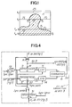
- the outline of the moving image is shown schematically on the screen of a videophone, such as the face of the speaker I (hatched part) standing out against a fixed background F generally one-color, or more precisely having a uniform color level.
- Each line can be divided into a ZF zone, resp. ZF 2 or two zones ZF 1 and ZF 2 representing the background F and varying from one image to the next only according to the noise of the camera, and / or in a central or lateral zone Z1 essentially mobile, representing the speaker 1 in motion or the bottom suddenly discovered.
- these zones are delimited by two image points M i and M 2 of coordinates x 1 and x 2 , or more precisely, the mobile zone ZI of the image of speaker 1 is delimited with respect to the background F by pairs of points M 1 , M 2 .
- the video signal representing the background shows a variation of constant amplitude along each line, only the points of the image area I are of interest for the reproduction of the image in the reception part of the videophone installation.
- the area M 1 M 2 of line L 2 is small, the area M 1 M 2 of line L 3 occupies the major part on the left of the screen and the area M 1 M 2 of line L 4 occupies the entire screen.
- the coding device transmits the image information of an area M 1 M 2 of a line by reducing the content real of this information received in the form of 8-bit words at 17.778 Mbit / s according to certain based criteria, on the one hand on the temporal redundancy of the image or treatment of only the parts of the moving image and, on the other hand, on spatial redundancy with a view to reducing the dynamic range of the signal transmitted by differential pulse code coding (MICD).
- MIMD differential pulse code coding
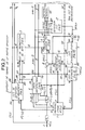
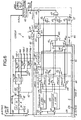
- the different circuits of the transmission part coding device, illustrated in FIG. 2, will be described below as the digital video signal at 17.778 Mbit / s from the camera and the associated sampler is processed.
- the coding device essentially comprises an image memory 1 which stores the odd frame followed by the even frame of the same image, a motion detection circuit 2, a bit distribution circuit 3, a linear predictor 4, a arithmetic unit 5 developing digital values DMAX, D characterizing the dynamics of the incoming video signal, a MIC encoder 6, a MIC decoder 7, an interpolation circuit 8 and a conditional spatial filtering circuit 9. It also includes two shift registers R 1 and R 2 connected in series, each at 231 x 8 stages, as well as a digital subtractor 41 and a digital adder 42 each having an input connected to the output 40 of the predictor 4.
- the input E of the coding device receives only the 8-bit binary words P (I, L) at the rate of 17.778 Mbit / s which are representative of the 231 visible points of a line L of an image I.
- Filtering and separation devices (not shown) precede upstream the ent row E, in order to separate the video information from the synchronization and suppression of frames and lines information. These devices are known from the prior art and do not belong to the scope of the invention.
- the multiplexing and transmission devices connected to the outputs of the coding device for the preparation of the outgoing digital channel at 2.048 Mbit / s are not described.
- a digital subtractor 20 receives by its direct input (+) a point word P (I, L) of a line L of the image to be processed I transmitted by the input E and by its inverse input (- ) a point word P '(1-1, L) of the line L of the previous image (1-1) transmitted by the output 10 of the image memory 1.
- the motion detection is based, according to the invention, on the point-to-point comparison of the border areas at the points M 1 and M 2 (FIG. 1) between the image currently received 1 at the input E and the previous image 1-1 stored in the image memory 1.
- the image memory 1 (FIG. 2) stores all the words P '(I, L) of points of an image, namely 288 x 231 8-bit words. These words P '(I, L) are in fact developed after coding, as will appear below.
- the memory 1 is for example made up of 34 modules with a capacity equal to 16 kbits. It is of the random access type (RAM) and is written and read at a period substantially less than the time interval T occupied by a point word P (I, L).
- Each point P (I, L) of the current image I and the corresponding point P '(I-1, L) of the previous image (I-1) are transmitted in two buffer registers 210 and 220 of the detection circuit 2, which are respectively interconnected between the direct input (+) of the subtractor 20 and the input E and between the inverse input (-) of the subtractor 20 and the output 10 of the image memory 1.
- the signal difference P (I, L) - P '(1-1, L) leaving the subtractor 20 is transmitted to the inputs of two arithmetic units 211 and 221.
- the first 211 transmits a signal indicating the absolute value of the difference
- This threshold S is for example equal to the difference between two or three successive levels of the 256 evenly distributed levels corresponding to the sampling of the incoming video signal. If P (I, L) - P '(I-1, L)
- the second arithmetic unit 221 transmits a "1” if the difference P (I, L) - P '(1-1, L) is positive, and a "0" otherwise.
- the output of comparator 23 and that of the arithmetic unit 221 are respectively connected to AND gates 213 and 223, having for example three inputs.
- One of the inputs 214, 224 of an AND gate 213, resp. 223, is directly connected to the output of comparator 23, resp. of unit 221.
- Each of the two other inputs are connected to this last input 214, 224 through a delay line 215, 216, resp. two delay lines 215-216, 225-226.
- These delay lines impose a delay equal to ⁇ and ensure that the amplitudes of three consecutive points of a line of the current image have fluctuated with a deviation greater than the threshold S and the same sign compared to the corresponding points of the previous image (1-1).
- the criterion implemented in the motion detection circuit 2 is thus based on the displacement of the transition or contour between the zones ZF 1 and ZF 2 on the one hand and the zone ZI on the other hand, that is to say - to say on the inter-image difference of the amplitudes of the points in movement. This criterion also discriminates the moving points of the noise of the camera by the choice of a suitable threshold value S.
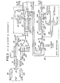
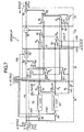
- the output of the AND gate 26 is connected to a logic circuit 27 which delivers the coordinates x 1 , x 2 of the points M 1 , M 2 detected.
- the circuit 27 comprises two monostable flip-flops 271 and 272 which are connected directly and through an inverter 270 to the output of the AND gate 26.
- the outputs of the flip-flops 271, 272 are connected to two AND gates 273 and 274.
- the other inputs of the AND gates 273, 274 are connected to the output of a point counter 277.
- This counter 277 is released after the end of the synchronization signal of each line following the first 53 points and is reset and blocked after the 231 th point following.
- the output of the counter 277 thus transmits the successive coordinates 1 to 231 of the line points.
- Buffer registers 275, 276 connected to the outputs of AND gates 273 and 274 store the coordinates x i and x 2 of the points M 1 and M 2 detected.
- an arithmetic unit 28 calculates the number of points NP of the zone ZI included in M 1 and M 2 , including the latter, and the average number of bits B to be assigned to each point actually transmitted.
- the coordinates x 1 and x 2 are read from registers 275 and 276 through AND reading gates 281 and 282.
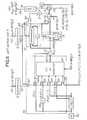
- the bit distribution circuit 3 shown in FIG. 4 comprises two down counters 31 and 32 which have their accounts respectively initialized at NB and at NP by reading a read-only memory (not shown) and the register 285 (FIG. 3) under the control of the line synchronization signal.
- An up-down counter 30 is also initialized at x 1 by reading the register 275 (FIG. 3) so that, as soon as its count reaches zero, it triggers the down-counts of the down-counters 31 and 32 at the frequency of point 1 / ⁇ , simultaneously with the serial transmission of point words P (I, L) from line L of register R 2 to input 600 of encoder 6 through subtractor 41 (Fig. 2).
- the outputs of circuits 33, 34 are connected to the direct (+) and inverse (-) inputs of a digital comparator 35.
- a digital comparator 35 When the difference of the numbers compared in comparator 35 is positive, its output 350 is in the state "1 »And commands the opening of an AND gate 36 whose other input receives at each period ⁇ the average number of bits B transmitted by the register 289 (Fig. 3).
- the counting input 311 of the down-counter 31 is connected to the output of the AND gate 36 and the down-counting input 321 of the down-counter 32 receives a "1" at each period ⁇ corresponding to the NP points of the mobile area ZI of the line L.
- the down-counter 31 counts down the number of available bits remaining to be allocated to the line L and that the down-counter 32 counts down the number of points remaining in the mobile zone ZI.
- the count C 2 of the down-counter 32 is decremented by the unit successively for each point between M 1 and M 2 .
- the count Ci of the down-counter 31 is reduced by B each time the output 350 of the comparator 35 is positive, that is to say when C 1 / B ⁇ C 2 or C 1 ⁇ NP ⁇ C 2 ⁇ NB and C 1 ⁇ NP ⁇ B ⁇ NP.
- the point is sampled, that is to say transmitted, the down-counter 31 is decremented by B and the gate 36 transmits via the bus 360 the word B to the down-counting input 311 of the down-counter 31 and at the input 601 of the coder 6, with a view to coding said point in MICD code.
- the point is subsampled, that is to say will be reconstituted by the interpolation in the interpolation circuit 8 (Fig. 2 and 10), the gate AND 36 remains closed and the down counter 31 is not decremented.
- the down-counter32 is always decremented by one when going from one point to the next.
- circuits 4 and 5 which are intended to reduce the dynamics of the incoming signal.
- the coder 6 of the coding device quantizes the digital differential signal DP (I, L) over a number of quantization levels NQ depending on the number of bits B assigned to each sampled point of a common line L by the bit distribution circuit 3.
- the coding carried out by the coder 6 is established on the absolute value
- the quantization levels are distributed - as shown below - throughout the range of variation of the incoming differential signal DP (I, L) for the mobile area ZI of a line L
- DMAX (L) and D (L) denote the maximum and average values of the incoming differential signal DP (I, L) for a line L, such that:
- the coder 6 evenly distributes the levels for half over the range [- D , + D
- Such coding makes it possible to avoid saturation of the coder, which produces dragging and visible point defects.
- two down counters 51 and 52 are decremented by the unit at each period ⁇ .
- the accounts of these downcounters have been initialized beforehand with the values x 1 and x 2 which are transmitted on their inputs 510, 520 to through the AND reading gates 281 and 282 through registers 275 and 276 (Fig. 3).
- the downcounter count 51 is not zero, its output 511 remains in the state “0 and closes AND gates 502, 503, 504, 505 and 506 through an AND gate 507.
- These gates 502 to 506 are intended to transmit the respective values P (I, L) from the output of the register R 1 , (P - 1) (I, L) from the output of the delay line 500, (P + 1) ( I, L - 1) from the penultimate stage of the register R 2 , P (I, L- 1) from the last stage or exit from the register R 2 and P '(I - 1, L) and (P - 1) '(I, L - 1) from the output 12 of the image memory 1 to the prediction circuit 501 when the outputs 511, 521 of the downcounters 51, 52 are in the state "1 •, through the AND gate 507.
- the account of the down-counter 51 is then equal to zero after the transmission of the point M 1 by the output of the register R 1 and the count of the second down-counter 52 is less than or equal to x 2 .
- the prediction circuit 501 transmits predicted words PP '(I, L) corresponds to all the points between M 1 and M 2 of each line L.
- the predicted value PP '(I, L) is transmitted to one of the inputs of a subtractor 53, the other input of which receives the real value P (I, L) from the output of the AND gate 502.
- is transmitted by the subtractor 53 to be added in an accumulator 55 to the sum of the absolute values previously calculated for the points M 1 to P - 1.
- is also compared in a comparator 56 with the maximum value of said previously received absolute values.
- the average value D is obtained by a divider 551 connected to the output of the AND gate 550 and receiving NP by the register 285 of the motion detection circuit 2 (Fig. 3).
- This average value D is stored in a memory 57, read during the coding of the line L proper, and is transmitted to the reverse input (-) of a subtractor 58 receiving by its direct input (+) the value DMAX transmitted via the AND gate 560.
- the subtractor 58 delivers DMAX - D to a memory 59, also read during the coding of the line L. Then the accumulator 55 and the comparator 56 are automatically reset to zero.
- the word B is transmitted to the common input 601 of a word detection circuit B 62 and of an arithmetic unit 63.
- the circuit 62 can for example be a comparator at 3 which delivers a "1 on its output each time that it detects a word such as B ⁇ 3.
- the NQ levels are split equally for half in the interval [- D , + D ] and in the double interval [- DMAX, - D [+] D, DMAX].
- the number NQ of levels is thus adapted by the coder 6 to the number of available bits NB per line as a function of the number of points NP in the zone ZI of the line L.
- All logical operations in the encoder and the decoder are established with 8-bit words and the output words VIN (I, L) of the encoder have B bits respectively for each line, with B which is greater than or equal to a first number predetermined for example equal to 3 and which is less than or equal to a second predetermined number for example equal to 6. For each sampled point, these operations have a duration less than ⁇ .
- the coder and decoder shown in FIGS. 6 and 7 that the level numbers are in increasing order from 0 to NQ - 1 for levels increasing from - DMAX to DMAX and that the coding level DP '(I, L) of a sample DP (I , L) is equal to the median quantization level of the quantization range to which DP (I, L) belongs.
- the decoders of the transmission and reception parts are respectively identical.
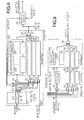
- the encoder 6 comprises a main channel whose logic circuits are common to the VIN calculations (I, L) according to the three preceding cases a, b, c, and are interconnected according to the order of the VIN calculation operations (I , L). These logic circuits relate first to the distinction of the three cases, then to a possible subtraction of DP (I, L) and a multiplication by NQ / 2, to the division by D or (DMAX - D ) followed by the possible addition of a factor such as NQ / 2-1, 3 NQ / 4-1 or NQ / 4-1.
- the sign SGN of DP (I, L) is obtained according to the following operations on the sign bit of DP (I, L) in state "0 if positive and in state” 1 "if negative: negation in 621, multiplication by 2 in 622 and subtraction from the unit in 623.
- the sets of circuits carrying out these last four calculations are designated respectively with the numbering prefixes 64, 65, 66 and 67 in Fig. 6.
- the arithmetic unit 63 delivers NQ / 2 to an input of a multiplier 651 of the encoder, NQ / 2-1 to an input of an AND gate 67a of the encoder and 75a of the decoder, NQ / 4 to the reverse input ( -) of a subtractor 740 of the decoder, and to an input of a divider 752 of the decoder, NQ / 4-1 at the digital input of an AND gate 75c of the decoder, 3 NQ / 4 at the reverse input (-) a subtractor 741 from the decoder, 3 NQ / 4-1 at the digital input of an AND gate 67b of the encoder and at the digital input of an AND gate 75b of the decoder.
- the memories 57 and 59 of the arithmetic unit 5 are read at the rate 1 / r after the detection of the synchronization signal relating to the line L + 2.
- the memory 57 delivers, through the link 570, the mean value D of the samples DP (I, L) at the reverse input (-) of a subtractor 640, at an input of an adder 641 and at the digital input of an AND gate 66a of the encoder 6 and at the respective digital inputs of AND gates 76a, 77d and 77c of the decoder 7 (Fig. 7).
- the AND gate 77c actually receives - D via a subtractor at the unit 770.
- the memory 59 delivers, via the link 590, the difference DMAX - D to the digital input of an AND gate 66bc of the encoder and the digital input of an AND 76bc door of the decoder.
- the logic circuit 64 distinguishing the three cases a), b), c) comprises the subtractor 640 and the adder 641 which have their other inputs connected to the output of the write AND gate 620, and two zero comparators 642 and 643 which have their respective inputs receiving DP (I, L) - D from the subtractor 640 and DP (I, L) + D from the adder 641.
- the outputs of the AND gate 620, of the subtractor 640 and of the adder 641 are also connected respectively to the digital inputs of the AND gates 65a, 65b and 65c.
- the AND control gate 64b has its inputs directly connected to the outputs of the comparators 642 and 643 and its output controlling the opening of the AND doors 65b and 67b and that of the door 66bc through an OR gate 660.
- the last AND control door 64c has its respective inputs connected to the outputs of comparators 642 and 643 through inverters 644 and 645 and controls the opening of AND gates 65c and 67c and that of AND gate 66bc through OR gate 660.
- the difference of DP (I, L) at zero or at D or the addition of DP (I, L) to D is transmitted in circuit 65, through an OR gate 650 connected to the outputs of AND gates 65a, 65b and 65c, to the other input of the multiplier by NQ / 2, 651.
- the division of the outgoing word of the multiplier 651 by D or (DMAX - D ) is performed in a divider 661 whose other input is connected through an OR gate 662 to the outputs of AND gates 66a and 66bc.
- the result of the previous division is added to SGN in an adder 663 and is then divided in a divider by 2, 664.
- the divider 664 is interconnected between the output of the adder 663 and one of the inputs of an adder 670
- the outputs of AND gates 67a, 67b and 67c are connected through an OR gate 671 to the other input of adder 670 so that it adds the last term NQ / 2-1, 3 NQ / 4-1 and NQ / 4-1 according to cases a, b and c.
- the output of the adder 670 common to the output 61 of the coder, transmits the number of the VIN level (I, L) in pure binary code at B bits to the input 70 of the decoder 7 (Fig. 7) and through a buffer memory 68, to an input of the multiplexing circuit of the transmission part (Fig. 2).
- the buffer memory 68 makes it possible to adapt the incoming digital bit rate at 17,778 Mbits / s to the outgoing bit rate at 2,048 Mbits / s. To do this, the words VIN (I, L) delivered by the output 61 are written under the control of the detection circuit of B 62 and are read at the frequency of 2.048 MHz.
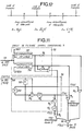
- the decoder 7 comprises a main channel whose logic circuits 74, 75, 76 and 77 are common to the calculations of DP '(I, L) according to the three cases a, b and c. These logical circuits follow one another according to the order of the elementary operations of the relations indicated above.
- Circuit 74 relates to the distinction of the three cases. It includes subtractors 740 and 741 and two zero comparators 742 and 743 whose inputs are respectively connected to the outputs of subtractors 740 and 741.
- the direct (+) inputs of subtractors 740 and 741 as well as that of a subtractor 750 are connected at the output of the write AND gate 720, the digital input 70 of which receives the word VIN (I, L) under the control of the output signal from the word detection circuit B 62 (FIG. 6). If VIN ⁇ NQ / 4 (case a), the output of comparator 742 is in state "1". If VIN. 3 NQ / 4 (case b), the output 74b of comparator 743 is in state "1".
- the inputs of a first AND gate 74a which controls the calculation of DP '(I, L) according to case a are connected directly to the output of comparator 742 and, through an inverter 744, to the output of comparator 743.
- the output of the AND gate 74a is connected to the control inputs of the AND gates 75a and 76a and to that of an AND gate 77a having its digital input receiving the zero value.
- the calculation of DP '(I, L) according to case b is controlled directly by the output 74b of the comparator 743 which is connected to the control inputs of the AND gates 75b and 77b and, through an OR gate 760, to that of the gate AND 76bc.
- VIN (I, L) The difference in VIN (I, L) to the number NQ / 2-1, 3 NQ / 4-1 or NQ / 4-1 is made by the subtractor 750 whose reverse input (-) is connected, through a door OR 751, at the outputs of AND gates 75a, 75b and 75c.
- the previous difference is divided by NQ / 4 in the divider 752 which is interconnected between the output of the subtractor 750 and an input of a multiplier 760.
- This multiplier 760 performs the product by D or (DMAX - D) which is transmitted to its other input by the outputs of AND gates 76a and 76bc, through an OR gate 761.
- the result of the multiplication is transmitted to an input of an adder 771.
- the other input of adder 771 receives the value 0, D or - D by the outputs of the gates 77a, 77b and 77c through an OR gate 772.
- the output of the adder 771 is common to that of the decoder 7 and transmits the 8-bit word DP '(I, L) to the other input of the adder 42, shown in FIG. 2.
- the adder 42 adds DP '(I, L) to the predicted point word PP (I, L) by the predictor 4 in order to transmit to the input 13 of the image memory 1, after interpolation and filtering (Fig.
- This PC sample value (I, L) is thus obtained after decoding and is recorded in the image memory 1 in order to establish the predicted samples of the next line and / or the next image.
- the numbers of the quantization levels NIV (I, L) and the values DP '(I, L) for each distribution of words designated by the value of B characterizing the mobile area ZI of a line L are fixed , that is to say, were previously saved in two read only memory blocks.
- the encoder 6 ' according to this second variant is shown in FIG. 8. It includes for example four read only memories 60 ' 3 , 60' 4 , 60 ' 5 and 60' 6 . These memories respectively comprise 8, 16, 32 and 64 memory cells which each store a number of quantization level VIN at 3, 4, 5 and 6 bits respectively. Each cell of a memory 601 'is addressed in reading by a comparator 602' which compares the sample word DP (I, L) which is transmitted by the output of the subtractor 41 (Fig. 2) to the common digital input 600 'of reading control doors ET 61' 3 , 61 ' 4 , 61' 5 , 61 ' 6 , at predetermined limits of quantification corresponding to the VIN level (I, L).
- the AND gates 61 ' 3 to 61' 6 are selectively opened by a circuit 62 'for recognizing B transmitted by the distribution circuit 3 (Fig. 4), through the output link 360 of the bit distribution circuit 3 ( Fig. 4).
- the recognition circuit 62 ′ compares B to 3, 4, 5 and 6 and, when B is equal to one of the preceding figures, commands through the bus 620 ′ the opening of the corresponding AND gate 61 ′ 3 to 61 ' 6 .
- one of the cells 601 'of the memory 60'g transmits through an OR gate 63' the word of level number VIN (I, L) at B bits to the buffer memory 68 and the multiplexing circuit of the transmission part and to the input 70 'of the decoder 7'.
- the memories 72 ' 3 to 72' 6 respectively comprise 8, 16, 32 and 64 memory cells 720 'containing the value of the quantization level DP' (I, L) at 8 bits corresponding to the level number VIN (I, L) stored in the cells of the respective memories 60 ' 3 to 60' 6 of the decoder 6 '.
- Each memory 72 ' 3 to 72' 6 is commanded to read by a register 73 ' 3 to 73' 6 .
- Such a register includes comparators at zero and matches the VIN number (I, L) transmitted by the corresponding AND gate 71 ' 3 to 71' 6 to the address of the corresponding memory cell 720 'in order to read the content DP '(I, L) of it.
- the word DP (I, L) corresponding to VIN (I, L) on the input 70 ' is transmitted, through an output gate OR 74', by one of the memory cells 72 ' 3 to 72' 6 to the other input of adder 42 (Fig. 2).
- the coding device no longer comprises the arithmetic unit 5 and that the preamble assigned to a line is more reduced since it no longer comprises the words D and DMAX - D.
- the number of bits NB available per line intended for the MICD coding of the points of the line is greater than according to the first variant according to which the coder adapts the quantization levels as a function of the average number of B bits per point word.
- the coding system according to this variant no longer comprises a shift register R I , the output of which is connected to the input 600 ′ of the MIC encoder 6 ′ through the subtractor 41.
- the movement detection circuit 2 computes x 1 and x 2 during the reception of a line L in the register R 1 . Then, during the reception of the next line L + 1, the circuit 2 calculates NP and B and the encoder MIC 6 'codes the words DP (I, L).
- the coding device receives at its input E only one frame out of two, for example all even frames.
- the missing frame of the image is reconstructed in the decoding device on reception by duplication or linear interpolation.
- the image memories of the coding device (Fig. 2) and of the decoding system (Fig. 13) are reduced to frame memories, that is to say have a capacity equal to half. from that 1 previously described.
- NB 462 bits are intended for coding the points to be transmitted, that is to say words of VIN level (1, L).
- the digital value PC (I, L) is substantially equal to P (I, L) transmitted to the input E of the coding device with the nearest quantization difference in the encoder and the decoder 6-7 (or 6'-7 '), when the point P (I, L) has been coded and selected under the control of the bit distribution circuit 3.
- PC (I, L) PP (I, L).
- DP '(I, L) is not calculated in the decoder 7 (or 7') and it is necessary to find a value close to the actual incoming value P (I, L) by linear interpolation and conditional filtering with respect to the points transmitted and coded in order to store it in the image memory 1 for the processing of the lines along the previously processed line L.
- the interpolated value PINT (I, L) of a subsampled point depends only on those of the points actually coded in MICD code and not on the predicted values PP (I, L) transmitted via output 40 of predictor 4.
- the interpolation circuit 8 comprises a circuit 80 for calculating the four preceding relationships and a circuit 87 for selecting one of these relationships as a function of the type of subsampling.
- the input 800 of the calculation circuit 80 receives in series at the frequency 1 / T the words PC (I, L) transmitted by the output 420 of the adder 42.
- the input 800 is connected to four delay lines in series 81 1 , 81 2 , 81 3 and 81 4 delaying each word PC (I, L) by T.
- the delay line 81 2 directly transmits the word PC (I, L) to a reading gate 82A, which is open for a point such as A.
- An adder 83 B has its inputs connected to the outputs of the delay lines 81 1 and 81 3 and has its output connected to the input of a reading door 82 8 through a divider by two 84 B.
- the output of the divider 84 B provides PINT (I, L) according to the interpolation relative to point B.
- a second adder 83 D has an input directly connected to the input 800 of the interpolation circuit and another input connected at the exit of the delay line 81 3 through a multiplier by three 85 D.
- a divider by four 84 D is connected to the output of the adder 83 D and transmits to an input of an ET reading gate D 82 D an interpolation word PINT (I, L) relating to a point such as D.
- a third adder 83 E has an input connected to the output of the delay line 81 1 , through a multiplier by three 85 E , and to its other input connected to the output of the delay line 81 4 .
- a divider by four 84 E is connected to the output of the adder 83 E and delivers to the digital input of a reading gate 82 E a word PINT (I, L) according to the interpolation relation of a point such as E.
- the selection circuit 87 comprises on the input side a comparator with three 870s which receives through the link 360 words B coming from the bit distribution circuit 3 (FIG. 4). It is recalled that for each word B equal to at least 3 corresponds the coding of a point word to be transmitted by the output of the encoder 6 (or 6 ') and the transmission of a word DP' (I, L) by the output of the decoder 7 (or 7 ') to the adder 42. If a word B is detected, the output 871 of the comparator 870 is in the state "1 during ⁇ , corresponding to a sampled point such as A, C or F (Fig. 12). If a point is subsampled, no word B is transmitted by the bit distribution circuit 3 and the output of the comparator is in the state "0" for ⁇ .
- the selection circuit 87 also includes four delay lines from ⁇ , 88 1 to 88 4 , which are connected in series with the output 871 of the comparator 870.
- An AND gate 89 B has three inputs, one of which is connected to the output of the delay line 88 2 through an inverter 890 8 and two of which are connected directly to the outputs of the delay lines 88 1 to 88 3 .
- a second AND gate 89 D has four inputs, two of which are directly connected to the output 871 of the comparator 870 and to the output of the delay line 88 3 , and two of which are connected to the outputs of the delay lines 88 1 and 88 2 through inverters 890 D and 890 ' D.
- a third AND gate 89 E has four inputs, two of which are directly connected to the outputs of the delay lines 88 1 and 88 4 and two other inputs of which are connected to the outputs of the delay lines 88 2 and 88 3 through two inverters 890 E and 890 ' E.
- the AND gates 89 D and 89 E are opened successively for two consecutive subsampled points of order 3.
- An OR gate 820 is connected to the outputs of AND gates 82 A , 82 C , 82 D and 82 E and successively transmits a word PINT interpolation (I, L) to input 900 of filtering circuit 9.
- the conditional spatial filtering circuit 9 shown in FIG. 10 essentially comprises a calculation circuit 90 for carrying out the three preceding relations and a circuit 95 for selecting the filterings according to the three relations.
- the input 900 of the calculation circuit 90 receives in series at the frequency 1 / T the interpolation words PINT (I, L) transmitted by the output gate OR 820 of the interpolation circuit 8.
- the input 900 is connected two delay lines of ⁇ 911 and 912 connected in series and an input of an adder 92 3 .
- the output of the delay line 911 delivers directly P '(I, L) to the digital input of an AND read gate 94 1 , which relates to a line not subsampled, and to one of the inputs an adder 92 2 .
- the adder 92 3 has its other input connected to the delay line 912 and transmits to the digital input of an AND read gate 94 3 , through a divider by 2, 93 3 , P '(I, L) according to the relation of the sub-sampling of order 3.
- the adder 92 2 has its other input connected to the output of the divider 93 3 and supplies to an input of an AND gate of reading 94 2 , through a divider by 2 , 93 2 , P '(I, L) according to the relation of the sub- second order sampling.
- the openings of the three ET doors 94 1 to 94 3 are selectively controlled by the three outputs of the filter selection circuit 95.
- the filtering selection circuit 95 comprises two comparators 951 and 952 which receive, at the start of the coding of each line, the number of points NP of the image area ZI which is delivered by the register 285 of the motion detection circuit 2 (Fig. 3). Comparator 951 compares NP to NB / 3 and sets its output to state "1" if NP> NB / 3. Comparator 952 compares NP to 2 NB / 3 and sets its output to state “1” if NP> 2 NB / 3.
- the output of comparator 952 is in the "1" state and directly controls the opening of the AND 94 3 gate relating to the filtering of a subsampled line of order 3.
- the output of one of AND reading gates 94 1 , 94 2 and 94 3 transmits in series, through an OR gate 98, the series of NP words P '(I, L) suitably filtered from the processed line L to input 13 of the memory image 1 for storage.
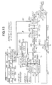
- the decoding device of the reception part is shown in the form of a block diagram in FIG. 13. It performs the same bit distribution, decoding, prediction, interpolation and filtering operations as those performed in the coding device of the transmission part.
- the words of the preamble of the line such as x 1 , x 2 , DMAX-D, D and possibly MP and the informative words VIN (I, L) representative of the points coded by the coding device of the transmission part of the remote speaker.
- All the operations necessary for calculating the decoding parameters of the VIN level words (I, L) are carried out during the time interval preceding the video signal and suitable for the reconstruction of the line synchronization signal. It will be recalled that all the circuits for reconstituting the synchronization signal and line suppression and the synchronization signal and frame suppression as well as the time base transmitting the supervision signals specific to decoding will not be detailed.
- the coordinate words x 1 and x 2 indicating the start M 1 and the end M 2 of the zone ZI of the line L are transmitted to the inputs 281 r and 282 r of an arithmetic unit 28 r ; the word x 1 is also delivered to the down counting input of the down counter 30 r of a bit distribution circuit 3 r .
- the arithmetic unit 28 r calculates, like the unit 28 of the motion detection circuit 2, the average number of bits B which has been assigned to each word VIN (I, L) and the number of points NP in the mobile area ZI of line L.
- Its register 289 r transmits B to the digital input of gate AND 36 r of a bit distribution circuit 3 r , similar to that 3 of FIG. 4, and its register 285 r transmits NP to the initialization input of the down-counter 32r and to one of the inputs of the multiplication circuit by NP 33 r of the bit distribution circuit 3 r and to the input 950 r d 'a conditional spatial filtering circuit 9 r similar to that 9 of FIG. 11.
- Each word B is delivered, through the bus 360 r , to the comparator at 3.870 r , from a linear interpolation circuit 8 r , similar to that 8 of FIG. 10, and at the common input 601 r of a detection circuit of B 62 r and of an arithmetic unit 63 r which are respectively analogous to those 62 and 63 of the encoder 6 shown in FIG. 6.
- the words D and DMAX-D of the line preamble supplied by the demultiplexing circuit of the reception part are also recorded in two buffer registers 57 r and 59 r as soon as the preamble of line L is detected and are transmitted under the command of the read signal 621 to the appropriate inputs of the decoder 7 r , via the buses 570 r and 590 r .
- the decoder 7 r calculates a quantization level DP '(I, L) each time its input 70 r has received a word of level VIN (I, L).
- DP '(I, L) is added in an adder 42 r to the corresponding predicted word PP (I, L) provided by the output 40 r of a linear predictor 4 r similar to that 4 of the coding device.
- This predictor 4 r possibly receives on its input 43 r a MP prediction indication word by the demultiplexing circuit, which word has been included in the preamble of the line.
- the predicted words PP (I, L) are established on the basis of the quantization levels calculated in the coder 6 (FIG. 6) and selected under the control of the bit distribution circuits 3 (Fig. 4) and 3 r .
- the output 11, of the memory 1 transmits to the input 44, of the predictor 4 r the point words P '(I, L) used for the calculation of the predicted word PP (I, L) according to one of the four relationships of prediction 1 to 4, and this at the frequency 1 / ⁇ .
- the read output 14 of the image memory 1 r also transmits in series at the frequency 1 / ⁇ the words P '(I, L) to the video part (screen) of the videophone after digital-analog conversion.
- the decoding device does not include an arithmetic unit 63 r and buffer registers 57 r and 59 r and has its MIC decoder similar to that illustrated in FIG. 9.
- the memory 1 r of the decoding device is a frame memory having a capacity reduced by half. The output, video side, of this frame memory is connected to a circuit for duplicating or reconstructing missing frames.
- the digital transmission channel can convey other secondary information signals, such as a channel intended for facsimile for example.
- the order of the sub-sampling can be greater than 3 and the number of bits N reserved for an image line can be arbitrary, but however defined in dependence on the incoming and outgoing digital bit rates.
- the information transmitted in the preamble of each line is such that it is sufficient to allow decoding suitable for reception. According to the first variant, they can also include x 1 , x 2 ; x 1 , x 2 - x 2 ; B , NP; or NQ, NP for example.
- the videophone signal can be a digital signal which is representative of monochrome black and white images or a digital component signal representative of a chromatic or luminance component of a video signal of color images. In the latter case, three sets of coding device and decoding device are provided in parallel.
Landscapes
- Engineering & Computer Science (AREA)
- Multimedia (AREA)
- Signal Processing (AREA)
- Compression Or Coding Systems Of Tv Signals (AREA)
- Two-Way Televisions, Distribution Of Moving Picture Or The Like (AREA)
- Compression, Expansion, Code Conversion, And Decoders (AREA)
Claims (17)
Applications Claiming Priority (2)
| Application Number | Priority Date | Filing Date | Title |
|---|---|---|---|
| FR7917798A FR2461405A1 (fr) | 1979-07-09 | 1979-07-09 | Systeme de codage et de decodage d'un signal visiophonique numerique |
| FR7917798 | 1979-07-09 |
Publications (2)
| Publication Number | Publication Date |
|---|---|
| EP0022713A1 EP0022713A1 (de) | 1981-01-21 |
| EP0022713B1 true EP0022713B1 (de) | 1983-03-30 |
Family
ID=9227686
Family Applications (1)
| Application Number | Title | Priority Date | Filing Date |
|---|---|---|---|
| EP80401030A Expired EP0022713B1 (de) | 1979-07-09 | 1980-07-08 | Anlage zum Codieren und Decodieren eines numerischen Fernsehtelefonsignals |
Country Status (5)
| Country | Link |
|---|---|
| US (1) | US4369464A (de) |
| EP (1) | EP0022713B1 (de) |
| JP (1) | JPS5656081A (de) |
| DE (1) | DE3062525D1 (de) |
| FR (1) | FR2461405A1 (de) |
Families Citing this family (32)
| Publication number | Priority date | Publication date | Assignee | Title |
|---|---|---|---|---|
| US4965825A (en) | 1981-11-03 | 1990-10-23 | The Personalized Mass Media Corporation | Signal processing apparatus and methods |
| USRE47642E1 (en) | 1981-11-03 | 2019-10-08 | Personalized Media Communications LLC | Signal processing apparatus and methods |
| US7831204B1 (en) | 1981-11-03 | 2010-11-09 | Personalized Media Communications, Llc | Signal processing apparatus and methods |
| US4488174A (en) * | 1982-06-01 | 1984-12-11 | International Business Machines Corporation | Method for eliminating motion induced flicker in a video image |
| US4494144A (en) * | 1982-06-28 | 1985-01-15 | At&T Bell Laboratories | Reduced bandwidth video transmission |
| FR2543384A1 (fr) * | 1983-03-22 | 1984-09-28 | Thomson Csf | Procede de codage adaptatif, et de decodage, d'une image de television, et dispositifs pour la mise en oeuvre de ce procede |
| GB8407764D0 (en) * | 1984-03-26 | 1984-05-02 | Indep Broadcasting Authority | Local movement detector |
| US4862264A (en) * | 1985-12-24 | 1989-08-29 | British Broadcasting Corporation | Method of coding a video signal for transmission in a restricted bandwidth |
| FR2599201A1 (fr) * | 1986-05-23 | 1987-11-27 | Trt Telecom Radio Electr | Dispositif de codage a modulation differentielle par impulsions codees, dispositif de decodage associe et systeme de transmission comportant au moins un tel dispositif de codage ou de decodage |
| JPS63190473A (ja) * | 1986-09-25 | 1988-08-08 | Nippon Board Computer Kk | 多階調画像デ−タの情報量圧縮方法及び装置 |
| JP2886172B2 (ja) * | 1987-08-28 | 1999-04-26 | ブリテツシユ・テレコミユニケイシヨンズ・パブリツク・リミテツド・カンパニー | 信号コーディング |
| JPS6477391A (en) * | 1987-09-18 | 1989-03-23 | Victor Company Of Japan | System and device for predictive coding |
| GB8724789D0 (en) * | 1987-10-19 | 1987-11-25 | British Telecomm | Signal coding |
| EP0330455A3 (de) * | 1988-02-22 | 1990-07-04 | Kabushiki Kaisha Toshiba | Vorrichtung zum Kodieren von Bildern |
| US4888640A (en) * | 1988-05-16 | 1989-12-19 | General Electric Company | Refresh system for digital signals |
| GB2222338B (en) * | 1988-08-27 | 1992-11-04 | Plessey Co Plc | Remote operated vehicle control |
| EP0411076A4 (en) * | 1989-01-16 | 1993-05-05 | Zeevi, Yehoshua Y | Video imaging system |
| FR2653953A1 (fr) * | 1989-10-27 | 1991-05-03 | Philips Electronique Lab | Dispositif de codage comportant un codeur a mots de longueur variable et dispositif de decodage associe. |
| US5303372A (en) * | 1991-06-24 | 1994-04-12 | Picker International, Inc. | Pipelined image data compression system |
| JP3133517B2 (ja) * | 1992-10-15 | 2001-02-13 | シャープ株式会社 | 画像領域検出装置、該画像検出装置を用いた画像符号化装置 |
| JPH0865665A (ja) * | 1994-08-25 | 1996-03-08 | Hitachi Denshi Ltd | 画像圧縮伝送方法および画像圧縮伝送システム |
| US20010002851A1 (en) * | 1995-04-14 | 2001-06-07 | Takao Shimada | Multimedia data processing system in network |
| GB2371638A (en) * | 2001-01-24 | 2002-07-31 | Hewlett Packard Co | Base station with data storage |
| US20060126718A1 (en) * | 2002-10-01 | 2006-06-15 | Avocent Corporation | Video compression encoder |
| US7321623B2 (en) * | 2002-10-01 | 2008-01-22 | Avocent Corporation | Video compression system |
| US7827458B1 (en) * | 2003-03-03 | 2010-11-02 | Apple Inc. | Packet loss error recovery |
| US9560371B2 (en) * | 2003-07-30 | 2017-01-31 | Avocent Corporation | Video compression system |
| US7457461B2 (en) * | 2004-06-25 | 2008-11-25 | Avocent Corporation | Video compression noise immunity |
| US7555570B2 (en) | 2006-02-17 | 2009-06-30 | Avocent Huntsville Corporation | Device and method for configuring a target device |
| US8718147B2 (en) * | 2006-02-17 | 2014-05-06 | Avocent Huntsville Corporation | Video compression algorithm |
| WO2007127452A2 (en) * | 2006-04-28 | 2007-11-08 | Avocent Corporation | Dvc delta commands |
| US8456380B2 (en) * | 2008-05-15 | 2013-06-04 | International Business Machines Corporation | Processing computer graphics generated by a remote computer for streaming to a client computer |
Family Cites Families (4)
| Publication number | Priority date | Publication date | Assignee | Title |
|---|---|---|---|---|
| US3439753A (en) * | 1966-04-19 | 1969-04-22 | Bell Telephone Labor Inc | Reduced bandwidth pulse modulation scheme using dual mode encoding in selected sub-block sampling periods |
| JPS5220091B2 (de) * | 1972-08-23 | 1977-06-01 | ||
| GB1511647A (en) * | 1974-08-02 | 1978-05-24 | Post Office | Digital television system |
| GB2003001A (en) * | 1977-08-16 | 1979-02-28 | Dennis T | Improvements in methods and apparatus for coding digital television signals |
-
1979
- 1979-07-09 FR FR7917798A patent/FR2461405A1/fr active Granted
-
1980
- 1980-07-08 DE DE8080401030T patent/DE3062525D1/de not_active Expired
- 1980-07-08 US US06/166,853 patent/US4369464A/en not_active Expired - Lifetime
- 1980-07-08 EP EP80401030A patent/EP0022713B1/de not_active Expired
- 1980-07-09 JP JP9281780A patent/JPS5656081A/ja active Pending
Also Published As
| Publication number | Publication date |
|---|---|
| JPS5656081A (en) | 1981-05-16 |
| US4369464A (en) | 1983-01-18 |
| DE3062525D1 (en) | 1983-05-05 |
| FR2461405B1 (de) | 1984-02-17 |
| FR2461405A1 (fr) | 1981-01-30 |
| EP0022713A1 (de) | 1981-01-21 |
Similar Documents
| Publication | Publication Date | Title |
|---|---|---|
| EP0022713B1 (de) | Anlage zum Codieren und Decodieren eines numerischen Fernsehtelefonsignals | |
| EP0558377B1 (de) | Videocodec, insbesondere für ein Bildtelefon | |
| FR2704706A1 (fr) | Système de traitement de signaux numériques. | |
| EP0414596B1 (de) | Vorrichtung zur Umwandlung der Bildfrequenz und des Zeilenanzähles für einen hochauflösenden Fernsehempfänger | |
| EP0416985B1 (de) | Verfahren zum Multiplexieren eines Tonsignals mit einem analogen Videosignal und entsprechendes Verteilungssystem für Standbilder mit Ton | |
| EP0141721A2 (de) | Empfangsvorrichtung in einem Übertragungssystem für asynchrone Videoinformation | |
| FR2650718A1 (fr) | Dispositif de transformation d'une information de mouvement en un signal de detection de mouvement a la frequence trame et au nombre de lignes souhaites pour un recepteur de television haute definition | |
| EP0347325A1 (de) | Verfahren und Installation zur Sendung von kompatiblen Hochauflösungsfernsehprogrammen | |
| EP0368400A1 (de) | Kodierung, Dekodierung und Übertragungssystem für Fernsehbilder | |
| WO1989010040A1 (fr) | Dispositif de codage et systeme de transmission d'images de television a haute definition | |
| EP0117161B1 (de) | Verfahren und Einrichtung zur digitalen Kodierung eines Bildes, insbesondere eines Fernsehbildes | |
| EP0294282B1 (de) | Verfahren zur temporalen Interpolation von Bildern und Einrichtung zur Durchführung dieses Verfahrens | |
| EP0365090B1 (de) | Einrichtung zum Verdoppeln der Rate von Fernsehbild-Signalen, und Fernsehbild-Dekodierer mit einer solchen Einrichtung | |
| EP0967576A1 (de) | Speicheradressierung in einem MPEG-Dekodierer | |
| EP0063990B1 (de) | Verfahren zur Bildübertragung mit beschränktem Datafluss; Übertragungssystem zur Durchführung dieses Verfahrens | |
| WO1990000846A1 (fr) | Codage et decodage d'images de television a haute definition | |
| FR2646047A1 (fr) | Procede et installation de codage et de transmission d'images animees sous forme numerique a bas debit | |
| EP0428216B1 (de) | Gerät zur verbesserten Dekodierung von HD-MAC-Fernsehsignalen | |
| EP0517719A1 (de) | Verfahren zur kodierung von bildsignalen | |
| EP0395507B1 (de) | Sende- und Empfangssystem zum Übertragen von beweglichen Farbbildern und Ton über unabhängige Kanäle | |
| FR2782878A1 (fr) | Systeme de compression et de decompression de signaux video numeriques | |
| WO1988009103A1 (fr) | Processeur de presentation stereoscopique d'images video | |
| EP0419353B1 (de) | Einrichtung zur hochauflösenden Fernsehprogramm-Dekodierung | |
| FR2684257A1 (fr) | Dispositif de decodage d'informations de mouvement en television haute definition. | |
| FR2780185A1 (fr) | Procede et dispositif de traitement d'images, comprimees notamment selon les normes mpeg |
Legal Events
| Date | Code | Title | Description |
|---|---|---|---|
| PUAI | Public reference made under article 153(3) epc to a published international application that has entered the european phase |
Free format text: ORIGINAL CODE: 0009012 |
|
| AK | Designated contracting states |
Designated state(s): BE DE GB IT NL |
|
| 17P | Request for examination filed |
Effective date: 19810129 |
|
| ITF | It: translation for a ep patent filed | ||
| GRAA | (expected) grant |
Free format text: ORIGINAL CODE: 0009210 |
|
| AK | Designated contracting states |
Designated state(s): BE DE GB IT NL |
|
| REF | Corresponds to: |
Ref document number: 3062525 Country of ref document: DE Date of ref document: 19830505 |
|
| PGFP | Annual fee paid to national office [announced via postgrant information from national office to epo] |
Ref country code: DE Payment date: 19840728 Year of fee payment: 5 |
|
| PG25 | Lapsed in a contracting state [announced via postgrant information from national office to epo] |
Ref country code: DE Effective date: 19880401 |
|
| GBPC | Gb: european patent ceased through non-payment of renewal fee | ||
| PG25 | Lapsed in a contracting state [announced via postgrant information from national office to epo] |
Ref country code: GB Free format text: LAPSE BECAUSE OF NON-PAYMENT OF DUE FEES Effective date: 19881118 |
|
| ITTA | It: last paid annual fee | ||
| PGFP | Annual fee paid to national office [announced via postgrant information from national office to epo] |
Ref country code: BE Payment date: 19940725 Year of fee payment: 15 |
|
| PGFP | Annual fee paid to national office [announced via postgrant information from national office to epo] |
Ref country code: NL Payment date: 19940731 Year of fee payment: 15 |
|
| PG25 | Lapsed in a contracting state [announced via postgrant information from national office to epo] |
Ref country code: BE Effective date: 19950731 |
|
| BERE | Be: lapsed |
Owner name: TEMIME JEAN PIERRE Effective date: 19950731 |
|
| PG25 | Lapsed in a contracting state [announced via postgrant information from national office to epo] |
Ref country code: NL Effective date: 19960201 |
|
| NLV4 | Nl: lapsed or anulled due to non-payment of the annual fee |
Effective date: 19960201 |
|
| PLBE | No opposition filed within time limit |
Free format text: ORIGINAL CODE: 0009261 |
|
| STAA | Information on the status of an ep patent application or granted ep patent |
Free format text: STATUS: NO OPPOSITION FILED WITHIN TIME LIMIT |