EP0419353B1 - Einrichtung zur hochauflösenden Fernsehprogramm-Dekodierung - Google Patents
Einrichtung zur hochauflösenden Fernsehprogramm-Dekodierung Download PDFInfo
- Publication number
- EP0419353B1 EP0419353B1 EP19900402586 EP90402586A EP0419353B1 EP 0419353 B1 EP0419353 B1 EP 0419353B1 EP 19900402586 EP19900402586 EP 19900402586 EP 90402586 A EP90402586 A EP 90402586A EP 0419353 B1 EP0419353 B1 EP 0419353B1
- Authority
- EP
- European Patent Office
- Prior art keywords
- mode
- field
- frames
- samples
- frame
- Prior art date
- Legal status (The legal status is an assumption and is not a legal conclusion. Google has not performed a legal analysis and makes no representation as to the accuracy of the status listed.)
- Expired - Lifetime
Links
Images


Classifications
-
- H—ELECTRICITY
- H04—ELECTRIC COMMUNICATION TECHNIQUE
- H04N—PICTORIAL COMMUNICATION, e.g. TELEVISION
- H04N7/00—Television systems
- H04N7/015—High-definition television systems
- H04N7/0152—High-definition television systems using spatial or temporal subsampling
- H04N7/0155—High-definition television systems using spatial or temporal subsampling using pixel blocks
Definitions
- the invention relates generally to systems for broadcasting high definition television programs, known as "HDTV", intended to provide an image having a number of lines and dots per line much higher than that corresponding to current standards.
- HDTV high definition television programs
- the European project EUREKA EU 95 will often be discussed later, which provides a system providing an image at the frequency of 50 Hz, having 1250 lines (instead of 625 lines) and a number of points per line doubled.
- the first problem is that of broadcasting HDTV programs on a television channel having a width insufficient to transmit all the pixels of all the successive video frames in full. This problem arises in particular from the fact that one wishes to broadcast HDTV programs on a MAC / PACKET television channel from a satellite.
- Subsampling is preceded by pre-filtering or spectrum shaping to avoid any spatial or temporal aliasing of the spectrum, the interpolation during decoding in each receiver being preceded or followed by reverse filtering of that which occurs on transmission (EP-A-0 316 232).
- the second problem is the condition that HDTV programs must be received and reproduced, with as little degradation as possible, by first generation television receivers, which imposes constraints on the techniques of subsampling and motion compensation.
- the subsampling structure In order that the necessary subsampling does not excessively degrade the quality of the HDTV image, the subsampling structure must be adapted to the temporal activity of the video signal, generally by separate selection between several structures for rectangular blocks. pixels of determined size (for example 16 x 16) in the image.
- Figures 4, 5, 6 and 7 correspond respectively to rearrangement by vertical mixing for four successive high definition frames T1, T2, T3 and T4 shown in type 3 structure, that is to say in 80 ms mode.
- the black dots represent all the samples of the high definition frames.
- the squares and diamonds respectively indicate the samples transmitted without arrangement and with rearrangement.
- the two digits assigned to each transmitted point indicate respectively the serial number of the sample in the line (direction x) and the serial number of the line in the high definition analysis frame (direction y). Line-to-line transfers are indicated by arrows.
- the distribution of the points transmitted on the frame t1, and it alone, is given in Figure 4bis, by way of example.
- Figures 8 and 9 show the rearrangement of the points transmitted in the case of the type 1 structure (20 ms), respectively for an odd high definition frame T1 or T3 and for a high definition even pair T2 or T4 frame. All the samples of the even frames are rearranged, while only the even samples of the odd frames are rearranged.
- Figure 10 corresponds to the type 2 structure where high definition frames 2 and 4 are not used); it shows that there is no rearrangement. Points 1.1; 3.1; 5.1; ... and 1.3; 3.3; ... are transmitted on the frame t1 or t3; the other points are transmitted on the frame t2 or t4.
- FIG. 11 the source image 10 is subjected to two linear pre-filtering processing (80 ms and 20 ms) at 20.
- the image is subjected to motion estimation, that is to say d time activity, at 22, and a nonlinear motion compensation processing operation at 24.
- a block 26 of adaptive subsampling determines a posteriori, by comparison of a block of samples (generally 16 x 16) of the original image with the images provided by the three channels leading to it, which of the three channels must be used for transmission.
- a block 27 of information on the space-time activity incorporates into assistance data DA the value of the motion vectors necessary for the reconstruction as well as switching information indicating the nature of the processing selected.
- This assistance data is transmitted with a speed which does not exceed 1.1 Mbit / s.
- the receiver therefore receives not only the transmission frames t, but also the DA data which contains switching information indicating, for each predetermined block of samples, which processing channel was used during coding as well as, if applicable, the value of the motion vector in each point treated, in the case where the track has given rise to compensation (case where it implements structure 2 and, sometimes also, structure 1 or even 3).
- Decoders conforming to the preamble of claim 1 are already known, which allow the reconstitution of HD frames at the cost of a high memory capacity (EP-A-322956).
- the invention aims to provide a decoder implementing an adaptive interpolation technique to the sub-sampling structures used, achieving an optimum compromise between the quality of the reconstituted high definition image and the complexity of the hardware implementation of the decoder and which is sufficiently flexible. to support possible modifications of the coding mode; for this, the decoder must calculate the missing samples in the vicinity of a block to allow an interpolation overflowing on the adjacent blocks.
- the invention provides a decoding device according to claim 1.
- Such a constitution can be described as "semi-cascaded".
- a decoder architecture comprising interpolators all placed in parallel, it has the advantage of facilitating conversions of sampling structure; compared to a fully cascaded architecture, with cascaded interpolations for each branch, the hardware complexity is very reduced.
- sampling structure conversion means thus formed provide additional interpolators, this time unique for each structure, with all of the samples, correctly positioned.
- the multiplexing of the initial frames transmitted and the frames with converted structure which can be described as "refresh", and the structure conversions are carried out according to a process adaptive to the information provided by the assistance data or again according to the interpolation mode.
- the decoder is designed to reconstruct all the luminance samples of a frame high definition video, using only three transmitted frame memories, with sampling at 13.5 MHz in the case, which will be considered only later, of the EUREKA EU 95 project.
- a similar architecture but simpler, may be provided for processing the chrominance samples sampled at 6.75 MHz, in line sequential, that is to say with transmission for each line of only one chrominance component out of two.
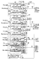
- the decoder is placed, in the receiver, downstream of the demultiplexer which selects the luminance samples, the chrominance samples being processed separately. It comprises three frame memories MEM T1, MEM T2 and MEM T3 placed in cascade and each having the capacity required to store the samples of a complete transmission frame. Their size will be assumed to be 16 points and 8 lines per transmission frame (which corresponds to 16 x 16 blocks on the image), but this size can be any modulo 4.
- the transmitted blocks can be coded differently from each other and correspond to any of the structures of type 1, 2 and 3.
- the reconstruction by interpolation of the samples of a coded block in a given structure requires to know adjacent samples in the blocks neighbors, presented in the same sampling structure.
- the decoder comprises a first converter of sampling structure CSE1, connected to the inputs and outputs of the three frame memories MEM T, the role of which is to supply all the transmission frames presented entirely according to the three structures.
- the three reconstructed high definition frames are applied to the three inputs of a high definition multiplexer 36 which selects, for each block, the samples corresponding to the analysis mode on transmission, identified by the assistance data.
- CSE1 also receives, on an input 56, the assistance data which is stored in a shift register 58 providing a delay corresponding to the processing frames.
- the subset 48 to 20 ms mode provides tc-20 frames in 20 ms mode, attacking the multiplexer 30: it includes, in addition to a block 80 ⁇ 20, a multiplexer 68 which, depending on the assistance data , transmits to output 66, either the current frame, or the output of converter 80 ⁇ 20.
- sub-assembly 50 for conversion to 80 ms mode provides, on an output 70, four successive frames in 80 ms mode.
- the internal signals have been indicated by following the indication tc with a number of four digits indicating the input mode and the converted mode. (2080 designating for example a frame resulting from a conversion from 20 ms mode to 80 ms mode).
- a last digit indicates the input source frame with which the converted frame is in time phase: the notation tc-2080-1 indicates for example a converted frame which is in time phase with the input source frame tr1.
- the interpolator circuit 30 can have the principle constitution shown in FIG. 14, which makes it possible to deal with the different cases which may arise, depending on whether the sequence number NOT of the current frame tr3 is odd or even.
- the interpolator circuit 30 comprises an interpolator 72 of type A and a spatial interpolator 74 of type B.
- the interpolator 74 makes it possible to reconstruct a high definition frame from two successive frames tc-40-1B and tc-40-2B, in the case where the current frame number NOT is odd.
- FIG. 15 shows, by way of example, the reconstruction of a sample P to be calculated from the speed vector V provided by the assistance data and point Q constituting the projection of P.
- the dashed frame indicates the opening of the interpolator.
- the lines of the odd and even fields are respectively indicated by solid lines and dashed lines.
- the motion compensation can be carried out in two different ways, both compatible with the implementation of the invention. The choice between them will be made according to the degree of acceptable complexity and the more or less complete nature of the compensation.
- a first solution consists in carrying out a projection, in the direction of movement, of the previous odd frame on the current even frame: this solution has the advantage of requiring no management of 40 ms mode break.
- the other solution consists in performing a filtering in the direction of movement, which has the advantage of better lending itself to an estimation of movement of the "block correspondence" type on the two adjacent frames.
- This filtering amounts to averaging the two adjacent odd frames, projected in the direction of movement on the current even frame.
- the mode breaks of the type * * 40 40 is managed in the following way: instead of averaging with equal weighting coefficients, a set of coefficients using the adjacent odd frame is used which is in 40 ms mode. One can in particular use the coefficients 0.25 and 0.75.
- the interpolator circuit 30 further comprises three multiplexers 80, 82 and 84 which make it possible to select the high definition 40 ms frame to be retained.
- CSE2 only has the function of providing converted signals either in 80 ms mode or in 20 ms mode from the 40 ms high definition frame provided by the interpolator circuit 30, its constitution is relatively simple. It can be the one shown in Figure 17.
- CSE2 provides, in addition to the signals which seem strictly necessary, four trm-80-n frames in 80 ms mode, which make it possible to manage the 80 ms mode break of the ** 8080 type (first two missing frames) .
- the interpolator circuit 30 which operates on instants in phase with tr1 and tr2 to provide four frames in 80 ms mode made up of samples with little error. This amounts to sampling in type 3 structure on an image whose frequency content is comparable to that of the 40 ms mode.
- Figure 18 also shows a smoothing circuit 88 which aims to reduce the risk of flickering of the image during 80 ms mode breaks (the cessation of this mode decreasing the spatial resolution). Smoothing consists of filtering on the last frame before switching to 80 ms mode or the last frame in 80 ms mode before returning to another mode, which can be carried out by a simple weighted average operation on the corresponding samples of the last frame from adjacent points.
- the smoothing circuit 88 can have the principle constitution shown in FIG. 19, as regards the frames having an odd NOT, for the odd points (left part of the Figure) and for the even points (right part of the Figure) . Smoothing done intervene the current point and four points belonging to two other frames in 80 ms mode.
- a multiplexer 90 whose control input 92 receives the frame sequence number and an indication of parity of points, switches a circuit made up of delay elements and multipliers. In the example shown in Figure 9, the weight assigned to the current point is 12, while the weight assigned to each of the adjacent points on the already reconstructed 80 ms frame is only 1.
- the elements providing a transmission delay equal to Tp, T1, Tf and Tp + T1 are indicated by a frame containing the corresponding notation. They have an operating rate equal to that of the transmission of samples.
- the reconstruction interpolators 32 and 34 respectively intended to reconstruct frames in 80 ms mode and in 20 ms mode, each time by interpolation, may have a relatively conventional constitution and, for this reason, will not be described in detail. They consist of several branches having delay elements and adders, a multiplexer being provided for alternately directing the even and odd samples towards the multiplexer high definition 36.
- the 80 ms mode interpolator 32 four frames tr 80-1, ... tr 80-4 converted into 80 ms mode and coming from a multiplexer 30 are used to generate a high definition image, one of which point on two is missing, and missing points are calculated; the opening of the filter can be 7 x 7 points from the high definition image.
- the current frame sampled in structure 1 (20 ms mode) is applied to the input; one point in four of the final high definition frame is therefore available. All the points are calculated by interpolation using filters having for example an opening of 9 x 9.
- the filters essentially comprise delay elements and adders, fed by a register allowing to have the 360 homologous points of four consecutive lines .
- the converter 48 to the 20 ms mode only has to perform the conversion from the type 3 structure (80 ms mode), because the sample blocks in 40 ms mode are processed by CSE2, due to the semi-assembly cascade. If therefore the samples of a block are in 20 or 40 ms mode, these samples are transmitted to CSE2 as they are, by the multiplexer 68.
- the converter 48 must generate new samples.
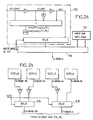
- the converter 48 can have the constitution shown in Figures 20 and 21 which comprises three branches, the outputs of which are connected to the inputs of a multiplexer 96 which directs one of the three inputs towards the output, according to the NOT frame sequence number.
- a first branch shown in detail in Figure 20, generates the samples when the sequence number of the current frame NOT is 1 or 2.
- each sample can be superimposed on a sample of the high definition frame.
- the output sample is generated by averaging the sample of the current frame with four neighboring samples in the high definition image, coming from the frame tr1.
- the weighting coefficients are 0.5 for the frame tr3, 0.125 for the four neighboring points of the frame tr1.
- the interpolation is then carried out from the four available neighboring points, belonging to the frames tr2 and tr4.
- the interpolation coefficients are the same for the four points and equal to 0.25.
- the samples are then generated by interpolation from four available neighboring points of the current frame tr3, with a weighting coefficient equal to 0.125, and horizontal interpolation of the two neighboring points of the frame tr4, with a weighting coefficient equal to 0.25.
- the interpolation from the four neighboring points is carried out with a diagram which can be the same as that shown in Figure 21.
- the 20 ⁇ 40 conversion is the same regardless of the parity of the current NOT frame sequence number (even or odd; on the contrary, the 80 ⁇ 40 conversion is a function of this parity and is a function of the position of the frame at calculate with respect to the current frame, which requires providing three different blocks for the 80 ⁇ 40 conversion.
- the frame generation block must practically have four branches.
- the selection between the output of the various branches is carried out using multiplexers 106 and 108.
- the circuits implemented can be of the same kind as those shown in Figure 22, modified to fulfill the above functions. In each case, the detailed constitution of the circuits can easily be established once the weighting coefficients have been chosen.
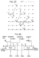
- High definition frame samples are indicated by black dots.
- Each of the points which intervene is designated by a number of three digits, the first designating the number of the modulo 4 sample on the line, the second designating the number of the modulo 2 line, and the third designating the number of the MEM memory concerned.
- the available samples are identified by a square.
- the samples to be calculated are identified by a circle surrounding the corresponding point.
- the 20 ⁇ 40 conversion in CSE1 is simpler than the 80 ⁇ 40 conversion, because it is identical regardless of NOT, even or odd. It is performed by the blocks 44 of the subsets 38, 40 and 42 ( Figure 13).
- the two frames in 40 ms mode required can be calculated from a single frame 20 ms of odd parity, which is either the current frame or the previous frame, as the case may be.
- multiplexers controlled by the assistance data make it possible to supply the interpolators 72 and 74 (interpolator A and interpolator B) of the reconstruction circuit 30 in 40 ms mode by interpolation, the necessary frames, under the form designated by: tc-40-1A tc-40-2A tc-40-1B tc-40-2B in Figure 13.
- the conversion 20 ⁇ 80 is carried out by block 52 of the sub-assembly 50 of CSE1 (block 2080 in FIG. 13).
- the constitution of the block 52 can be simple, because the structures 1 and 3, corresponding to the modes 20 and 80 ms, are superimposable.
- the so-called temporal conversion 80 ⁇ 80 in the event of an 80 ms mode break is the one which is the most complex to process.
- 80 ms mode breaks occur at the start or end of 80 ms sampling periods of a block. These breaks are detected by a module (not shown) operating on the assistance data stored in the register 58 ( Figure 13). The module detects, for each block of samples, if the current mode is 80 ms. By comparison with the three other available frames of the sample block located at the same location, it identifies the mode breaks.
- Type 1 failure * 80 80 80 , for which the successive frames available are always frames having NOT 1, 4, 3 and 2.
- Type 2 failure * * 80 80 , for which the successive frames available are frames with NOT 2, 1, 4 and 3.
- Type 3 failure 80 80 80 * , for which the successive frames available are frames with NOT 3, 2, 1 and 4.
- Figure 30 where the notations are similar to those of Figure 13, shows how the multiplexing of the output signals provided by the various branches of the sub-assembly 50 is carried out in order to provide the set of transmission frames necessary for an image in 80 ms mode.
- the invention is susceptible of numerous variant embodiments.
- filtering is advantageously carried out on the last complete frame sampled in 80 ms mode before switching to 80 ms mode and the last frame in 80 ms mode before returning to another mode.
- This filtering can consist of a weighted average operation on the points of the last frame, using the adjacent points of this 80 ms type frame.
- an additional memory for assistance data can be provided to control the multiplexing and leave the image at low resolution if a group of four analysis frames 80 ms is isolated between two groups of frames in 20 or 40 ms mode.
- the interpolation modes which have been given are only examples. Motion compensation has only been described when it is applied in 40 ms mode, but it can also be applied in 80 ms mode.
- the weighting coefficients can be different from those given.
- Coding in 40 ms mode uses the frame hopping solution.
- two color video frame memories are used to simultaneously provide two consecutive transmitted frames, as in the case of luminance.
- a multiplexer constituting a double switch makes it possible to select the previous frame or the next frame with respect to the current frame and to correctly route the even and odd video frames.
- the circuit is preceded by an element giving a delay of several lines, compensating for the difference between the delays due to the greater complexity of the decoding of the luminance.
- the information coming from the two frame memories is directed to line memories, on the one hand for the 40 ms branch (even and odd frame), on the other hand for the 20 ms branch (current frame).
- the frame memories may have a smaller capacity than in the case of luminance, for example 360 points for 312 lines instead of 720 points for 312 lines.
- the mode of transmission chosen will be the same for luminance and chrominance in a given block; only one recognition circuit is therefore necessary in the coder: it uses for example a criterion of minimum of the sum of the squares of the deviations.
Landscapes
- Engineering & Computer Science (AREA)
- Multimedia (AREA)
- Signal Processing (AREA)
- Compression Or Coding Systems Of Tv Signals (AREA)
- Television Systems (AREA)
Claims (7)
- Vorrichtung zur Dekodierung von in schmalem Kanal gesendeten Fernsehprogrammen hoher Auflösung, welche von einem Kodierer mit Unter-Abtastung kommen, welcher Abtastwerte liefert, die gemäß einer Struktur (S3) mit Fünfer-Zeilenanordnung in vier Teilbildern, einer jeden zweiten Punkt der Struktur mit Fünfer-Zeilenanordnung in vier Teilbildern behaltenden Struktur (S1) und einer Teilbildsprungstruktur (S2) verteilt sind, wobei das Bild in Blöcke von Abtastwerten zerlegt ist, welche gemäß den unterschiedlichen Strukturen verteilt sein können, wobei die Vorrichtung wenigstens für die Luminanzabtastwerte Mittel (MEMT1, MEMT2, MEMT3) zur Speicherung von drei aufeinanderfolgenden Übertragungsteilbildern, welche Mittel es gestatten, über vier Übertragungsteilbilder (tr1, tr2, tr3, tr4) zu verfügen, Mittel, welche es gestatten, die fehlenden Abtastwerte zu rekonstruieren, und Mittel zum Mischen der erzielten Resultate umfaßt, um ein vollständiges Bild hoher Auflösung zu liefern,
dadurch gekennzeichnet, daß die Mittel, welche eine Rekonstruktion der Abtastwerte gestatten, umfassen
einen ersten Abtaststrukturumwandler (CSE1), welcher das aktuelle Übertragungsteilbild (tr3) und ein vorhergehendes Übertragungsteilbild (tr4) und zwei spätere Übertragungsteilbilder (tr1, tr2) empfängt und als Ausgabe ein vollständiges Teilbild mit Struktur (S1), wenigstens zwei aufeinanderfolgende, vollständige Teilbilder mit Struktur (S2) und vier aufeinanderfolgende, vollständige Teilbilder mit Struktur (S3) in unter-abgetasteter Form liefert;
eine Interpolationsschaltung (30) gemäß der Teilbildsprungstruktur (S2), welche das vollständige Teilbild hoher Auflösung mit Struktur (S2) aus der Ausgabe des ersten Umwandlers rekonstruiert;
einen zweiten Abtaststrukturumwandler (CSE2), welcher die Abtastwerte des von der Interpolationsschaltung kommenden Teilbilds mit Teilbildsprungstruktur (S2) empfängt und - aus dem rekonstruierten Teilbild hoher Auflösung mit Teilbildsprungstruktur (S2), den vier vollständigen Teilbildern mit Struktur (S3) und einem Teilbild mit Struktur (S3) - mit Struktur (S1) und (S3) unter-abgestastete Teilbilder rekonstruiert, welche den Blöcken des aktuellen Teilbilds entsprechen;
zwei Zusatzinterpolationsschaltungen (32, 34), welche parallel arbeiten und aus von dem zweiten Abtaststrukturumwandler gelieferten Abtastwerten mit Strukturen (S1) und (S3) alle Abtastwerte eines rekonstruierten Teilbilds hoher Auflösung mit Struktur (S1) und (S3) liefern;
und daß ein zu den Mischungsmitteln gehörender Multiplexer das endgültige Bild hoher Auflösung durch Auswahl von Blöcken in den rekonstruierten Teilbildern als Funktion von Hilfsdaten (DA) liefert, welche von dem Kodierer kommend empfangen werden. - Vorrichtung nach Anspruch 1, dadurch gekennzeichnet, daß der erste Abtaststrukturumwandler (CSE1) umfaßt:
drei Umwandler-Untereinheiten (38, 40, 42) in die Teilbildsprungstruktur (S2) aus zwei anderen Strukturen, welche als Funktion der Hilfsdaten ausgewählt sind,
eine Umwandler-Untereinheit (48) in die Struktur (S1), welche jeden zweiten Punkt der Struktur (S3) mit Fünfer-Zeilenanordnung in vier Teilbildern behält,
eine Umwandler-Untereinheit (50) in die Struktur (S3) mit Fünfer-Zeilenanordnung in vier Teilbildern, welche es gestattet, die zeitlichen Unterbrechungen der Strukturen mit Fünfer-Zeilenanordnung in vier Teilbildern zu verwalten. - Vorrichtung nach Anspruch 2, dadurch gekennzeichnet, daß eine der Umwandler-Untereinheiten (38) in die Teilbildsprungstruktur (S2) einen von der Struktur mit Fünfer-Zeilenanordnung in vier Teilbildern ausgehenden Umwandler (46) und einen von der jeden zweiten Punkt behaltenden Struktur (S1) ausgehenden Umwandler (44) umfaßt und derart ausgebildet ist, daß sie einem ersten Interpolator (72) der Interpolationsschaltung (30) entweder ein von einem der Umwandler (44,46) kommendes Teilbild oder ein aktuelles Teilbild liefert.
- Vorrichtung nach Anspruch 3, dadurch gekennzeichnet, daß jede der anderen Umwandler-Untereinheiten (40, 42) in die Teilbildsprungstruktur (S2) einen von der Struktur mit Fünfer-Zeilenanordnung in vier Teilbildern ausgehenden Umwandler (46) und einen von der jeden zweiten Punkt behaltenden Struktur (S1) ausgehenden Umwandler (44) umfaßt und derart ausgebildet ist, daß sie einem zweiten Interpolator (74) der Interpolationsschaltung (30) Blöcke mit Teilbildsprungstruktur liefert.
- Vorrichtung nach Anspruch 4, dadurch gekennzeichnet, daß der zweite Interpolator (74) ein räumlicher Interpolator zur Rekonstruktion von Teilbildern hoher Auflösung aus zwei aufeinanderfolgenden Teilbildern mit Teilbildsprungstruktur (S2) ist und einen Interpolator (76) in der Vertikalrichtung ansteuert.
- Vorrichtung nach nach einem der Ansprüche 3 bis 5, dadurch gekennzeichnet, daß der erste Interpolator (72) ein Interpolator zur Rekonstruktion von Teilbildern hoher Auflösung ist, welcher eine Bewegungskompensationsschaltung (78) ansteuert.
- Vorrichtung nach einem der Ansprüche 3 bis 6, dadurch gekennzeichnet, daß der zweite Umwandler (CSE2) derart ausgebildet ist, daß er von rekonstruierten Teilbildern hoher Auflösung mit Teilbildsprungstruktur (S2) und von dem Resultat der durch den ersten Interpolator (72) durchgeführten Interpolation ausgehend der Struktur mit Fünfer-Zeilenanordnung in vier Teilbildern entsprechende Modusunterbrechungssignale und Signale mit jeden zweiten Punkt behaltender Struktur (S1) liefert, welche von den Resultaten der Rekonstruktion ausgehend abgetastet sind.
Applications Claiming Priority (2)
| Application Number | Priority Date | Filing Date | Title |
|---|---|---|---|
| FR8912410 | 1989-09-21 | ||
| FR8912410A FR2652223B1 (fr) | 1989-09-21 | 1989-09-21 | Dispositif de decodage de programmes de television haute definition. |
Publications (2)
| Publication Number | Publication Date |
|---|---|
| EP0419353A1 EP0419353A1 (de) | 1991-03-27 |
| EP0419353B1 true EP0419353B1 (de) | 1995-05-10 |
Family
ID=9385731
Family Applications (1)
| Application Number | Title | Priority Date | Filing Date |
|---|---|---|---|
| EP19900402586 Expired - Lifetime EP0419353B1 (de) | 1989-09-21 | 1990-09-19 | Einrichtung zur hochauflösenden Fernsehprogramm-Dekodierung |
Country Status (3)
| Country | Link |
|---|---|
| EP (1) | EP0419353B1 (de) |
| DE (1) | DE69019279T2 (de) |
| FR (1) | FR2652223B1 (de) |
Families Citing this family (1)
| Publication number | Priority date | Publication date | Assignee | Title |
|---|---|---|---|---|
| DE4213551A1 (de) * | 1992-04-24 | 1993-10-28 | Thomson Brandt Gmbh | Verfahren und Vorrichtung zur Film-Mode-Detektion |
Family Cites Families (3)
| Publication number | Priority date | Publication date | Assignee | Title |
|---|---|---|---|---|
| DE3850952T2 (de) * | 1987-12-22 | 1995-02-23 | Philips Nv | Videosignalkodierung und -dekodierung mit einem adaptiven Filter. |
| GB2219458A (en) * | 1988-06-01 | 1989-12-06 | Philips Electronic Associated | Processing sub-sampled signals |
| FR2633135B1 (fr) * | 1988-06-17 | 1990-11-09 | France Etat Armement | Decodeur pour recepteur de programmes de television haute definition diffuses sur canal etroit |
-
1989
- 1989-09-21 FR FR8912410A patent/FR2652223B1/fr not_active Expired - Lifetime
-
1990
- 1990-09-19 DE DE1990619279 patent/DE69019279T2/de not_active Expired - Fee Related
- 1990-09-19 EP EP19900402586 patent/EP0419353B1/de not_active Expired - Lifetime
Also Published As
| Publication number | Publication date |
|---|---|
| DE69019279T2 (de) | 1995-11-02 |
| FR2652223A1 (fr) | 1991-03-22 |
| DE69019279D1 (de) | 1995-06-14 |
| FR2652223B1 (fr) | 1991-12-06 |
| EP0419353A1 (de) | 1991-03-27 |
Similar Documents
| Publication | Publication Date | Title |
|---|---|---|
| EP0330279B1 (de) | Einrichtung zur raumzeitlichen Unterabtastung von digitalen Videosignalen, die eine Folge verschachtelter oder sequentieller Bilder darstellen, Übertragungssystem von Fernsehbildern mit hoher Auflösung mit einer solchen Einrichtung und Stufen zum Senden und Empfangen in einem solchen System | |
| FR2552606A1 (fr) | Signal de television de haute definition pour systeme de conversion des standards film-television | |
| FR2551292A1 (fr) | Dispositif de visualisation d'images de television couleur a balayage progressif | |
| FR2704706A1 (fr) | Système de traitement de signaux numériques. | |
| EP0337565B1 (de) | Einrichtung zur Kodierung von Signalen, die eine Folge von Bildern darstellen und Übertragungssystem von Fernsehbildern mit hoher Auflösung mit einer solchen Einrichtung | |
| EP0368400B1 (de) | Kodierung, Dekodierung und Übertragungssystem für Fernsehbilder | |
| EP0418952A1 (de) | Vorrichtung zum Codieren von zweidimensionalen Informationen und entsprechende Decodiervorrichtung | |
| EP0347325A1 (de) | Verfahren und Installation zur Sendung von kompatiblen Hochauflösungsfernsehprogrammen | |
| EP0412003B1 (de) | Vorrichtung zur Umwandlung einer Bewegungsinformation in ein Bewegungsdetektionssignal mit gewünschter Zeilenanzahl und Halbbildfrequenz für einen Hochauflösungsfernsehempfänger | |
| EP0419353B1 (de) | Einrichtung zur hochauflösenden Fernsehprogramm-Dekodierung | |
| EP0365090B1 (de) | Einrichtung zum Verdoppeln der Rate von Fernsehbild-Signalen, und Fernsehbild-Dekodierer mit einer solchen Einrichtung | |
| EP0404238B1 (de) | Signalverarbeitungseinrichtungen vor und nach Übertragung und/oder Speicherung mit Datenflussverminderung, und Verfahren zur Übertragung und/oder Speicherung von Signalen mit solchen Einrichtungen | |
| EP0350122A1 (de) | Verfahren und Einrichtungen zur Kodierung und Dekodierung von Fernsehbildern mit hoher Auflösung und Übertragungssysteme mit solchen Einrichtungen | |
| FR2616287A1 (fr) | Procede de traitement de signaux video echantillonnes selon un reseau d'echantillonnage different d'une image a l'autre et convertisseur de signaux video pour la mise en oeuvre de ce procede | |
| EP0428216B1 (de) | Gerät zur verbesserten Dekodierung von HD-MAC-Fernsehsignalen | |
| EP0408460B1 (de) | Verfahren und System zur Sendung von Fernsehprogrammen mit hoher Auflösung | |
| EP0321357B1 (de) | Verfahren zur Unterabtastung einer Folge von elektronischen Bildern in der Achse der Bewegung | |
| FR2644956A1 (fr) | Dispositif de conversion de frequence trame pour un recepteur de television haute definition et procede de detection du mouvement dans une image de television codee | |
| FR2633472A1 (fr) | Dispositif de sous-echantillonnage temporel et d'interpolation temporelle compensee en mouvement dans une sequence d'images entrelacees, utilisation d'un tel dispositif dans les dispositifs de codage et de decodage d'un systeme de transmission d'images de television a haute definition, et dispositifs de codage et de decodage pour un tel systeme | |
| JP2003525549A (ja) | サブサンプリングを用いるビデオ圧縮 | |
| FR2633135A1 (fr) | Decodeur pour recepteur de programmes de television haute definition diffuses sur canal etroit | |
| FR2649847A2 (fr) | Procede et systeme de diffusion de programme de television a haute definition | |
| FR2656189A1 (fr) | Systeme et decodeur de signal haute definition de la famille mac/paquet, compatibles avec une transmission en large bande et en bande etroite. | |
| FR2630283A1 (fr) | Dispositif de sous-echantillonnage temporel et d'interpolation temporelle compensee en mouvement dans une sequence d'images entrelacees, utilisation d'un tel dispositif dans les circuits de codage/decodage d'un systeme de transmission d'images de tele a haute definition; dispositifs de codage/decodage pour un tel systeme | |
| FR2644027A1 (fr) | Dispositif de codage et de decodage d'images de television, systeme de transmission d'images de television incorporant de tels dispositifs, et etages d'emission et de reception d'un tel systeme |
Legal Events
| Date | Code | Title | Description |
|---|---|---|---|
| PUAI | Public reference made under article 153(3) epc to a published international application that has entered the european phase |
Free format text: ORIGINAL CODE: 0009012 |
|
| AK | Designated contracting states |
Kind code of ref document: A1 Designated state(s): DE GB NL |
|
| 17P | Request for examination filed |
Effective date: 19910701 |
|
| 17Q | First examination report despatched |
Effective date: 19931214 |
|
| RAP1 | Party data changed (applicant data changed or rights of an application transferred) |
Owner name: ETABLISSEMENT PUBLIC TELEDIFFUSION DE FRANCE Owner name: FRANCE TELECOM |
|
| GRAA | (expected) grant |
Free format text: ORIGINAL CODE: 0009210 |
|
| AK | Designated contracting states |
Kind code of ref document: B1 Designated state(s): DE GB NL |
|
| PG25 | Lapsed in a contracting state [announced via postgrant information from national office to epo] |
Ref country code: NL Free format text: LAPSE BECAUSE OF NON-PAYMENT OF DUE FEES Effective date: 19950510 |
|
| GBT | Gb: translation of ep patent filed (gb section 77(6)(a)/1977) |
Effective date: 19950517 |
|
| REF | Corresponds to: |
Ref document number: 69019279 Country of ref document: DE Date of ref document: 19950614 |
|
| NLV1 | Nl: lapsed or annulled due to failure to fulfill the requirements of art. 29p and 29m of the patents act | ||
| PLBE | No opposition filed within time limit |
Free format text: ORIGINAL CODE: 0009261 |
|
| STAA | Information on the status of an ep patent application or granted ep patent |
Free format text: STATUS: NO OPPOSITION FILED WITHIN TIME LIMIT |
|
| 26N | No opposition filed | ||
| PGFP | Annual fee paid to national office [announced via postgrant information from national office to epo] |
Ref country code: GB Payment date: 19960823 Year of fee payment: 7 |
|
| PGFP | Annual fee paid to national office [announced via postgrant information from national office to epo] |
Ref country code: DE Payment date: 19960830 Year of fee payment: 7 |
|
| PG25 | Lapsed in a contracting state [announced via postgrant information from national office to epo] |
Ref country code: GB Free format text: LAPSE BECAUSE OF NON-PAYMENT OF DUE FEES Effective date: 19970919 |
|
| GBPC | Gb: european patent ceased through non-payment of renewal fee |
Effective date: 19970919 |
|
| PG25 | Lapsed in a contracting state [announced via postgrant information from national office to epo] |
Ref country code: DE Free format text: LAPSE BECAUSE OF NON-PAYMENT OF DUE FEES Effective date: 19980603 |