EP0022528B1 - Dip-coating method and apparatus - Google Patents
Dip-coating method and apparatus Download PDFInfo
- Publication number
- EP0022528B1 EP0022528B1 EP80103826A EP80103826A EP0022528B1 EP 0022528 B1 EP0022528 B1 EP 0022528B1 EP 80103826 A EP80103826 A EP 80103826A EP 80103826 A EP80103826 A EP 80103826A EP 0022528 B1 EP0022528 B1 EP 0022528B1
- Authority
- EP
- European Patent Office
- Prior art keywords
- tank
- coating solution
- coating
- dip
- article
- Prior art date
- Legal status (The legal status is an assumption and is not a legal conclusion. Google has not performed a legal analysis and makes no representation as to the accuracy of the status listed.)
- Expired
Links
- 238000003618 dip coating Methods 0.000 title claims description 23
- 239000011248 coating agent Substances 0.000 claims description 113
- 238000000576 coating method Methods 0.000 claims description 113
- XLYOFNOQVPJJNP-UHFFFAOYSA-N water Substances O XLYOFNOQVPJJNP-UHFFFAOYSA-N 0.000 claims description 9
- 238000007598 dipping method Methods 0.000 claims description 3
- 238000000034 method Methods 0.000 description 21
- 230000007547 defect Effects 0.000 description 8
- 239000007788 liquid Substances 0.000 description 6
- 239000000428 dust Substances 0.000 description 4
- 239000000725 suspension Substances 0.000 description 4
- YXFVVABEGXRONW-UHFFFAOYSA-N Toluene Chemical compound CC1=CC=CC=C1 YXFVVABEGXRONW-UHFFFAOYSA-N 0.000 description 3
- 230000000694 effects Effects 0.000 description 3
- 239000000113 methacrylic resin Substances 0.000 description 3
- 230000005855 radiation Effects 0.000 description 3
- IJGRMHOSHXDMSA-UHFFFAOYSA-N Atomic nitrogen Chemical compound N#N IJGRMHOSHXDMSA-UHFFFAOYSA-N 0.000 description 2
- BQCADISMDOOEFD-UHFFFAOYSA-N Silver Chemical compound [Ag] BQCADISMDOOEFD-UHFFFAOYSA-N 0.000 description 2
- 229910001873 dinitrogen Inorganic materials 0.000 description 2
- 238000011156 evaluation Methods 0.000 description 2
- 239000012535 impurity Substances 0.000 description 2
- 238000005259 measurement Methods 0.000 description 2
- QSHDDOUJBYECFT-UHFFFAOYSA-N mercury Chemical compound [Hg] QSHDDOUJBYECFT-UHFFFAOYSA-N 0.000 description 2
- 229910052753 mercury Inorganic materials 0.000 description 2
- 230000003287 optical effect Effects 0.000 description 2
- BDERNNFJNOPAEC-UHFFFAOYSA-N propan-1-ol Chemical compound CCCO BDERNNFJNOPAEC-UHFFFAOYSA-N 0.000 description 2
- 229910052709 silver Inorganic materials 0.000 description 2
- 239000004332 silver Substances 0.000 description 2
- KMNCBSZOIQAUFX-UHFFFAOYSA-N 2-ethoxy-1,2-diphenylethanone Chemical compound C=1C=CC=CC=1C(OCC)C(=O)C1=CC=CC=C1 KMNCBSZOIQAUFX-UHFFFAOYSA-N 0.000 description 1
- FIHBHSQYSYVZQE-UHFFFAOYSA-N 6-prop-2-enoyloxyhexyl prop-2-enoate Chemical compound C=CC(=O)OCCCCCCOC(=O)C=C FIHBHSQYSYVZQE-UHFFFAOYSA-N 0.000 description 1
- 239000000853 adhesive Substances 0.000 description 1
- 230000001070 adhesive effect Effects 0.000 description 1
- 230000008033 biological extinction Effects 0.000 description 1
- 239000000919 ceramic Substances 0.000 description 1
- 238000000151 deposition Methods 0.000 description 1
- 239000003599 detergent Substances 0.000 description 1
- 238000007599 discharging Methods 0.000 description 1
- 230000008030 elimination Effects 0.000 description 1
- 238000003379 elimination reaction Methods 0.000 description 1
- 239000012530 fluid Substances 0.000 description 1
- 239000013505 freshwater Substances 0.000 description 1
- 239000007789 gas Substances 0.000 description 1
- 230000001678 irradiating effect Effects 0.000 description 1
- 229910052751 metal Inorganic materials 0.000 description 1
- 239000002184 metal Substances 0.000 description 1
- 239000002245 particle Substances 0.000 description 1
- 238000005192 partition Methods 0.000 description 1
- 239000000375 suspending agent Substances 0.000 description 1
- 239000000057 synthetic resin Substances 0.000 description 1
- 229920003002 synthetic resin Polymers 0.000 description 1
- QXJQHYBHAIHNGG-UHFFFAOYSA-N trimethylolethane Chemical compound OCC(C)(CO)CO QXJQHYBHAIHNGG-UHFFFAOYSA-N 0.000 description 1
- 230000010356 wave oscillation Effects 0.000 description 1
Images


Classifications
-
- B—PERFORMING OPERATIONS; TRANSPORTING
- B05—SPRAYING OR ATOMISING IN GENERAL; APPLYING FLUENT MATERIALS TO SURFACES, IN GENERAL
- B05D—PROCESSES FOR APPLYING FLUENT MATERIALS TO SURFACES, IN GENERAL
- B05D1/00—Processes for applying liquids or other fluent materials
- B05D1/18—Processes for applying liquids or other fluent materials performed by dipping
-
- B—PERFORMING OPERATIONS; TRANSPORTING
- B01—PHYSICAL OR CHEMICAL PROCESSES OR APPARATUS IN GENERAL
- B01D—SEPARATION
- B01D19/00—Degasification of liquids
- B01D19/0021—Degasification of liquids by bringing the liquid in a thin layer
-
- B—PERFORMING OPERATIONS; TRANSPORTING
- B01—PHYSICAL OR CHEMICAL PROCESSES OR APPARATUS IN GENERAL
- B01D—SEPARATION
- B01D19/00—Degasification of liquids
- B01D19/0073—Degasification of liquids by a method not covered by groups B01D19/0005 - B01D19/0042
- B01D19/0078—Degasification of liquids by a method not covered by groups B01D19/0005 - B01D19/0042 by vibration
-
- B—PERFORMING OPERATIONS; TRANSPORTING
- B05—SPRAYING OR ATOMISING IN GENERAL; APPLYING FLUENT MATERIALS TO SURFACES, IN GENERAL
- B05C—APPARATUS FOR APPLYING FLUENT MATERIALS TO SURFACES, IN GENERAL
- B05C3/00—Apparatus in which the work is brought into contact with a bulk quantity of liquid or other fluent material
- B05C3/02—Apparatus in which the work is brought into contact with a bulk quantity of liquid or other fluent material the work being immersed in the liquid or other fluent material
- B05C3/04—Apparatus in which the work is brought into contact with a bulk quantity of liquid or other fluent material the work being immersed in the liquid or other fluent material with special provision for agitating the work or the liquid or other fluent material
- B05C3/05—Apparatus in which the work is brought into contact with a bulk quantity of liquid or other fluent material the work being immersed in the liquid or other fluent material with special provision for agitating the work or the liquid or other fluent material by applying vibrations thereto
Definitions
- This invention relates to a dip-coating method and apparatus for forming a flat smooth coated film surface on the surface of an article.
- the present invention is to provide a method and apparatus for obtaining a very fine coated film having no irregularity on an article to be coated by making ultrasonic waves act on a coating solution and forming a uniform surface liquid flow in a coating solution tank.
- the present invention is applied to coat the surface of such optical product as a mirror or lens, a remarkable effect that a product quality of such excellent level as has never been realized before will be obtained.
- a method of forming a coated film on the surface of an article to be coated by dipping the article in a coating solution and then pulling the article up out of the coating solution at a low speed has been already utilized as a dip-coating method.
- This method has demerits that the article to be coated is limited to be of a simple shape having no solution pool but has merits that the obtained coating film is high in the smoothness and that the entire surface of the article to be coated can be coated at once, and thus is ased for such surface coating as the under coating or upper coating of a metal or synthetic resin article.
- the coated article is to be used for such optical product as a mirror, lens or glazing or in case it is to be printed or plated as a secondary work, a higher smoothness of the coating film having no irregularity will be required.
- the prior art document DE-A-27 18 758 discloses the metallizing of ceramic tubes, by introducing the tubes into a suspension comprising silver particles, adhesive oxides and suspension agents and irradiating the suspension with ultrasonic waves. According to this method the speed of introducing and extracting the tubes into and from the suspension is of major importance.
- this apparatus used and claimed with this application includes a circulation pump for the silver suspension, there is no reference as to jetting the coating solution uniformly and parallelly with the bottom of the coating solution tank.
- the radiation of ultrasonic waves is considered to be required to drive out air present as dissolved in the coating solution and to destroy the air layer brought in as deposited on the surface of the article to be coated when the article is dipped in the coating solution.
- the bubbles generated by the cavitation stay for a long time on the coating solution surface or around the coated article at the coating solution surface, such defects as "blemishes” and "pinholes” will be generated or traces of the bubbles will be left when the article is pulled up. Therefore, the strong surface liquid flow is considered to be required to prevent it.
- a coating solution in a coating solution tank 1 overflows a dam 4 and comes to an intermediate tank 6 through an overflow pocket 5.
- a funnel 9 for pouring in a solution to be added is attached to the intermediate tank 6.
- the solution from the intermediate tank 6 is pressurized by a circulating pump 7 and passes through a filter 8, impurities in the solution will be removed.
- the solution coming out of the filter is returned to the coating solution tank 1 to circulate.
- reference numeral 2 indicates a water tank for containing an ultrasonic oscillator.
- the coating solution tank 1 is dipped in the water tank 2 and is placed near the ultrasonic wave oscillator 3, ultrasonic waves generated from the ultrasonic oscillator 3 will produce ultrasonic wave pressure waves in the coating solution through the wall of the coating solution tank 1 through water in the water tank 2.
- nozzles 10 and 11 are respectively a water feeding nozzle and water discharging nozzle.
- the ultrasonic wave oscillator 3 is outside the coating solution tank 1 and the oscillating surface of the ultrasonic wave oscillator 3 is arranged as opposed to the bottom surface of the coating solution tank 1 but, when the coating solution is inert to the ultrasonic wave oscillator and is not likely to corrode it, the oscillating surface may be directed upward and arranged directly within the coating solution tank.
- the coating solution temperature shows a tendency to rise with the ultrasonic wave oscillation of the coating solution.
- a cooler for the coating solution may be provided in the circulating line.
- the width direction of the tank means a direction at right angles with the direction in which the solution flows toward the overflow pocket and "the lengthwise direction of the tank” means a direction parallel with it, as shown in Figure 3.
- the frequency of the ultrasonic waves radiated to the coating solution is 1 to 100 KHz or preferably 5 to 50 KHz. If the frequency is less than 1 KHz, a cavitation will be hard to occur. If the frequency exceeds 100 KHz, generation and extinction of cavitation bubbles in the solution will take time and therefore the ultrasonic waves will not act to the solution effectively.
- the strength of the ultrasonic waves may be 0.2 to 2 w./cm 2 . In case the strength of the ultrasonic waves is less than 0.2 w./cm. 2 , the cavitation pressure waves will be weak. When the strength is in excess of 5 wJcm.2, the propagation of the ultrasonic waves will be obstructed by the cavitation bubbles generated. Further, the strength of the ultrasonic waves for the solution capacity is in a preferable range of about 10 to 100 w./I.
- the feed of the coating solution to the coating solution tank on which ultrasonic waves are made to act should form a uniform surface liquid flow toward the overflow pocket on the surface of the coating solution tank in order to mare the cavitation bubbles produced by the ultrasonic waves smoothly flow away in turn from the coating solution tank surface while making the cavitation bubbles act on the articles to be coated.
- the cavitation bubbles When the cavitation bubbles are not made to smoothly flow away, they will cover the entire coating solution tank surface, further air present as dissolved in the coating solution or the destroyed air layer on the surface of the article to be coated will stay in the bubbles to leave on the coated film such defects as "blemishes", "splashes” and "pinholes" or traces of bubbles.
- the above mentioned uniform surface liquid flow is formed by jetting the coating solution uniformly and parallel to the bottom surface of the tank, from the side on which the coating solution overflows toward the bottom of the tank at the side opposite the jet nozzle.
- Figures 3 and 4 are explanatory views of a method and apparatus for forming a uniform liquid surface flow.
- Figure 3 is of a case that the length of the direction in which the coating solution flows on the rectangular solution surface of the coating solution tank is not larger than 3 times the depth of the coating solution tank and
- Figure 4 is of a case that the length exceeds 3 times.
- a solution inflow port 13 to feed the coating solution is connected to a jetting nozzle 14 having many orifices and located on the overflow pocket 5 side of the bottom surface of the coating solution tank.
- the solution jetted out of the jetting nozzle 14 is deaerated by the ultrasonic waves radiated from the bottom of the coating solution tank, rises against the tank wall opposed to the jetting nozzle 14, becomes a turned surface flow on the solution surface, overflows the dam 4 and reaches the overflow pocket 5.
- the coating solution increases again in the amount of air present as dissolved by contacting air while flowing on the coating solution tank solution surface and down into the overflow pocket.
- the amount of air is reduced by subjecting the coating solution to the radiation of ultrasonic waves in the tank bottom after the solution was circulated through overflow pocket 5 and again jetted out of the jetting nozzle 14.
- the flow formed on the coating solution tank surface has not only an action of making the cavitation bubbles flow away but also an effect of quickly flowing into the overflow pocket 5 the dust and dirt floating on the coating solution surface, which dust and dirt are ones dropped from air over the tank on the coating solution or brought in the solution together with the articles depositing their surfaces.
- the solution flow jetted out of the jetting nozzle 14 will not reach the opposed tank wall, will become a turned flow on the way and will flow into the overflow pocket 5.
- the fluid resistance will become maximum, the flow will be remarkably inhibited, the jetted solution flow will become such short-circuiting flow as will soon flow into the overflow pocket 5 and no uniform surface flow will be obtained.
- Figure 4 is of a method of forming a uniform strong surface flow in a tank long in the flowing direction.
- a second solution inflow port 13' and a second solution jetting nozzle 14' connected to it are provided on the side opposite the over flow pocket side of the tank bottom.
- the solution jetted out of the second jetting nozzle 14' turns against the tank wall surface to become a surface flow.
- Each of the above mentioned first jetting nozzle 14 and second jetting nozzle 14' may have not only many orifices as in Figure 9 but also a slit as in Figure 10. In order to obtain a uniform surface flow, it is essential to have a uniform jetted volume over each jetting part of the jetting nozzle.
- the coating solution should be jetted parallelly with the tank bottom surface.
- the flow velocity of the coating solution on the surface of the coating solution tank may be 2 to 100 cm/sec or preferably 10 to 50 cm/sec. In case the flow velocity of the coating solution is less than 2 cm/sec, it will not be preferable because "blemishes” and “splashes” will occur. In case the flow velocity exceeds 100 cm/sec, it will not be preferable because "flow patterns" will occur.
- the present invention relates to a method and apparatus for radiating ultrasonic waves to a coating solution, and feeding the coating solution uniformly and parallel to the tank bottom surface from the side on which the coating solution overflows toward the bottom of the tank at the side opposite the jet nozzle whereby a uniform surface flow toward the overflow pocket will be formed over the tank width direction on the surface of the coating solution tank, the bubbles generated by the cavitation of the ultrasonic waves will not stay on the solution surface and such effect by the ultrasonic waves as is mentioned above will effectively be achieved.
- a solution consisting of 30 parts of trimethylolethane trimethyacrylate, 10 parts of 1,6-hexanediol diacrylate, 30 parts of n-propyl alcohol, 30 parts of toluene and 2 parts of benzoin ethylether was put into each of a dip-coating apparatus (Example 1) formed of the process in Figure 1 and the coating solution tank in Figure 3, a dip-coating apparatus (Control 1) formed of the process in Figure 1 and the coating solution tank in Figure 6, a dip-coating apparatus (Control 2) formed of the process in Figure 1 and the coating solution tank in Figure 7 and a dip-coating apparatus (Control 3) formed of the process in Figure 1 and the coating solution tank in Figure 8 and each apparatus was operated while actuating the ultrasonic wave oscillating device.
- nozzle as is shown in Figure 9 was used for the jetting nozzles 14, of Example 1 and Control 1.
- the size of the tank was of 700 mm long x 250 mm wide x 400 mm deep and the flow velocity on the surface of the coating solution was made 20 cm/sec.
- the ultrasonic wave oscillating device was of a frequency of 28 KHz and a strength of 1.0 w/cm 2 .
- Controls 4 and 5 are respectively of a case that only the ultrasonic wave oscillating device was stopped while the circulation of the solution was left as it was in Example 1 and a case that only the circulation of the solution was stopped while the ultrasonic wave oscillating device was left as it was.
- the obtained evaluation results are shown in Table 1.
- Example 2 The treating solution used in Example 1 was put into each of a dip-coating apparatus (Example 2) formed of the process in Figure 1 and the coating solution tank in Figure 4 and a dip-coating apparatus (Control 6) formed of the process in Figure 1 and the coating solution tank in Figure 5 and each apparatus was operated while actuating the ultrasonic wave oscillating device.
- a dip-coating apparatus Example 2 formed of the process in Figure 1 and the coating solution tank in Figure 4
- Control 6 a dip-coating apparatus formed of the process in Figure 1 and the coating solution tank in Figure 5 and each apparatus was operated while actuating the ultrasonic wave oscillating device.
- Such nozzle as is shown in Figure 9 was used for the jetting nozzles 14, 14' of Example 2 and Control 6.
- the size of the tank was of 700 mm long x 250 mm wide x 150 mm deep and the flow velocity on the surface of the coating solution was made 30 cm/sec.
- the ultrasonic wave oscillating device was of a frequency of 28 KHz and a strength of 0.7 w/cm 2 .
- a uniform methacrylic resin plate of 630 mm long x 230 mm wide x 3 mm thick was dipped in each of these tanks in the same way as in Example 1, was pulled up into clean air at a velocity of 0.5 cm/sec and was immediately irradiated for 5 seconds with ultraviolet rays from a high voltage mercury lamp of 2 KW in a clean nitrogen gas current.
- the appearance of each obtained coated plate was as in Table 2.
- Control 7 is of a case that only the nozzles 14 and 14' were stopped while the ultrasonic wave oscillating device was left as it was in Example 2 and Control 8 is of a case that only ultrasonic wave oscillating device was stopped in Example 2. The obtained results are shown in Table 2.
- Example 1 was repeated except that the ultrasonic waves were irradiated through both the longer side walls of the tank, a dip-coating tank of 700 mm long x 400 mm wide x 400 mm deep was used, and a methacrylic resin plate of 600 mm long x 380 mm wide x 10 mm thick was dipped.
Landscapes
- Chemical & Material Sciences (AREA)
- Chemical Kinetics & Catalysis (AREA)
- Coating Apparatus (AREA)
- Application Of Or Painting With Fluid Materials (AREA)
Description
- This invention relates to a dip-coating method and apparatus for forming a flat smooth coated film surface on the surface of an article.
- More particularly the present invention is to provide a method and apparatus for obtaining a very fine coated film having no irregularity on an article to be coated by making ultrasonic waves act on a coating solution and forming a uniform surface liquid flow in a coating solution tank. In case the present invention is applied to coat the surface of such optical product as a mirror or lens, a remarkable effect that a product quality of such excellent level as has never been realized before will be obtained.
- A method of forming a coated film on the surface of an article to be coated by dipping the article in a coating solution and then pulling the article up out of the coating solution at a low speed has been already utilized as a dip-coating method. This method has demerits that the article to be coated is limited to be of a simple shape having no solution pool but has merits that the obtained coating film is high in the smoothness and that the entire surface of the article to be coated can be coated at once, and thus is ased for such surface coating as the under coating or upper coating of a metal or synthetic resin article.
- In case the coated article is to be used for such optical product as a mirror, lens or glazing or in case it is to be printed or plated as a secondary work, a higher smoothness of the coating film having no irregularity will be required.
- These irregularity defects are called "pinholes", "blemishes", "splashes" and "craters" in the industry. Their elimination is made an important problem of securing the quality.
- These defects of the coated film can be comparatively reduced by such methods wherein the article to be coated is washed and cleaned with a detergent or the like in advance, such impurities as dust in the coating solution are filtered off to be removed and further the entire atmosphere in which the article is dip-coated and the coated film is dried to be hardened is cleaned. But the smoothness of the coated film has been insufficient.
- Further, there is an attempt to secure the smoothness of the coated film by flowing the coating solution in the coating tank so quietly as to spout. However, it has not been satisfactory.
- The prior art document DE-A-27 18 758 discloses the metallizing of ceramic tubes, by introducing the tubes into a suspension comprising silver particles, adhesive oxides and suspension agents and irradiating the suspension with ultrasonic waves. According to this method the speed of introducing and extracting the tubes into and from the suspension is of major importance. Though this apparatus used and claimed with this application includes a circulation pump for the silver suspension, there is no reference as to jetting the coating solution uniformly and parallelly with the bottom of the coating solution tank.
- . As a result of studies, it has been discovered that, when ultrasonic waves are made to act on a coating solution in the case of dip-coating so that cavitation bubbles generated by the ultrasonic waves may remove gas dissolved in the coating solution or adhered to the surface of the article from the solution or the article and a strong uniform liquid flow is formed on the surface of a coating solution, the above mentioned defects of the coated film will be substantially eliminated.
- The subject matter of the present invention therefore is the method and apparatus as defined in
claim 1 and 6, respectively. - The subclaims as stated below relate to preferred embodiments of this method and apparatus.
- The radiation of ultrasonic waves is considered to be required to drive out air present as dissolved in the coating solution and to destroy the air layer brought in as deposited on the surface of the article to be coated when the article is dipped in the coating solution. When the bubbles generated by the cavitation stay for a long time on the coating solution surface or around the coated article at the coating solution surface, such defects as "blemishes" and "pinholes" will be generated or traces of the bubbles will be left when the article is pulled up. Therefore, the strong surface liquid flow is considered to be required to prevent it.
- The present invention shall be described in the following with reference to the drawings in which:
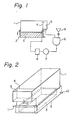
- Figure 1 is a flow sheet showing an embodiment of the present invention;
- Figure 2 is a perspective view of an embodiment of the invention in which an ultrasonic wave oscillator is set on the bottom outside a coating solution tank;
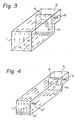
- Figures 3 and 4 are perspective views of embodiments of the invention each showing a coating solution tank and coating solution flow pattern;
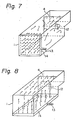
- Figures 5, 6, 7 and 8 are perspective views each showing another coating solution tank and coating solution flow pattern not embraced by the invention and used for comparison purposes.
- Figures 9 and 10 are perspective views respectively of a jetting nozzle having many orifices and a jetting nozzle having a slit;
- Figure 11 is a sectioned view showing the posture of fitting the jetting nozzle to the bottom surface of the coating tank.
- In Figure 1, a coating solution in a
coating solution tank 1 overflows adam 4 and comes to an intermediate tank 6 through anoverflow pocket 5. A funnel 9 for pouring in a solution to be added is attached to the intermediate tank 6. When the solution from the intermediate tank 6 is pressurized by a circulatingpump 7 and passes through afilter 8, impurities in the solution will be removed. The solution coming out of the filter is returned to thecoating solution tank 1 to circulate. - In the drawing,
reference numeral 2 indicates a water tank for containing an ultrasonic oscillator. When thecoating solution tank 1 is dipped in thewater tank 2 and is placed near theultrasonic wave oscillator 3, ultrasonic waves generated from theultrasonic oscillator 3 will produce ultrasonic wave pressure waves in the coating solution through the wall of thecoating solution tank 1 through water in thewater tank 2. - It is preferable to take in fresh water from outside in the water tank so as to play a part as of a medium to propagate ultrasonic waves and a part of removing heat generated from the ultrasonic wave oscillator.
- In Figure 2, nozzles 10 and 11 are respectively a water feeding nozzle and water discharging nozzle.
- In each of Figures 1 and 2, the
ultrasonic wave oscillator 3 is outside thecoating solution tank 1 and the oscillating surface of theultrasonic wave oscillator 3 is arranged as opposed to the bottom surface of thecoating solution tank 1 but, when the coating solution is inert to the ultrasonic wave oscillator and is not likely to corrode it, the oscillating surface may be directed upward and arranged directly within the coating solution tank. - Further, the coating solution temperature shows a tendency to rise with the ultrasonic wave oscillation of the coating solution. However, when it is not desirable to the coating solution, a cooler for the coating solution may be provided in the circulating line.
- In the present invention, when many articles to be coated are to be dipped over the width direction of the tank, a method of radiating ultraonic waves from the tank bottom as in Figure 2 will be effective but, when there are only one article to be coated over the width direction of the tank, the article will not be shaded by other articles and thus ultrasonic waves may be radiated from the side of the tank. In the present specification, "the width direction of the tank" means a direction at right angles with the direction in which the solution flows toward the overflow pocket and "the lengthwise direction of the tank" means a direction parallel with it, as shown in Figure 3.
- The frequency of the ultrasonic waves radiated to the coating solution is 1 to 100 KHz or preferably 5 to 50 KHz. If the frequency is less than 1 KHz, a cavitation will be hard to occur. If the frequency exceeds 100 KHz, generation and extinction of cavitation bubbles in the solution will take time and therefore the ultrasonic waves will not act to the solution effectively.
- The strength of the ultrasonic waves may be 0.2 to 2 w./cm2. In case the strength of the ultrasonic waves is less than 0.2 w./cm.2, the cavitation pressure waves will be weak. When the strength is in excess of 5 wJcm.2, the propagation of the ultrasonic waves will be obstructed by the cavitation bubbles generated. Further, the strength of the ultrasonic waves for the solution capacity is in a preferable range of about 10 to 100 w./I.
- It is necessary that the feed of the coating solution to the coating solution tank on which ultrasonic waves are made to act should form a uniform surface liquid flow toward the overflow pocket on the surface of the coating solution tank in order to mare the cavitation bubbles produced by the ultrasonic waves smoothly flow away in turn from the coating solution tank surface while making the cavitation bubbles act on the articles to be coated. When the cavitation bubbles are not made to smoothly flow away, they will cover the entire coating solution tank surface, further air present as dissolved in the coating solution or the destroyed air layer on the surface of the article to be coated will stay in the bubbles to leave on the coated film such defects as "blemishes", "splashes" and "pinholes" or traces of bubbles.
- It has been discovered that the above mentioned uniform surface liquid flow is formed by jetting the coating solution uniformly and parallel to the bottom surface of the tank, from the side on which the coating solution overflows toward the bottom of the tank at the side opposite the jet nozzle.
- Each of Figures 3 and 4 is an explanatory view of a method and apparatus for forming a uniform liquid surface flow. Figure 3 is of a case that the length of the direction in which the coating solution flows on the rectangular solution surface of the coating solution tank is not larger than 3 times the depth of the coating solution tank and Figure 4 is of a case that the length exceeds 3 times.
- In Figure 3, a
solution inflow port 13 to feed the coating solution is connected to ajetting nozzle 14 having many orifices and located on theoverflow pocket 5 side of the bottom surface of the coating solution tank. - As illustrated, the solution jetted out of the
jetting nozzle 14 is deaerated by the ultrasonic waves radiated from the bottom of the coating solution tank, rises against the tank wall opposed to thejetting nozzle 14, becomes a turned surface flow on the solution surface, overflows thedam 4 and reaches theoverflow pocket 5. - The coating solution increases again in the amount of air present as dissolved by contacting air while flowing on the coating solution tank solution surface and down into the overflow pocket. However, the amount of air is reduced by subjecting the coating solution to the radiation of ultrasonic waves in the tank bottom after the solution was circulated through
overflow pocket 5 and again jetted out of thejetting nozzle 14. - . The flow formed on the coating solution tank surface has not only an action of making the cavitation bubbles flow away but also an effect of quickly flowing into the
overflow pocket 5 the dust and dirt floating on the coating solution surface, which dust and dirt are ones dropped from air over the tank on the coating solution or brought in the solution together with the articles depositing their surfaces. - Further, in the
coating solution tank 1, such a strong circulating flow is made by thisjetting nozzle 14 that there is no dead space anywhere. - If the length in the flowing direction of the tank is large, as shown in Figure 5, the solution flow jetted out of the
jetting nozzle 14 will not reach the opposed tank wall, will become a turned flow on the way and will flow into theoverflow pocket 5. Particularly, if the entire article to be coated enters the coating solution tank, the fluid resistance will become maximum, the flow will be remarkably inhibited, the jetted solution flow will become such short-circuiting flow as will soon flow into theoverflow pocket 5 and no uniform surface flow will be obtained. - In such flowing state, the part on the side opposite the
overflow pocket 5 of the coating solution tank will become a dead space and, on the solution surface, not only the cavitation bubbles will stay but also the dust and dirt floating on the solution surface will not smoothly flow into the overflow pocket and "blemishes" and "pinholes" will be generated on the coated film surface. - In order to made the solution flow reach the opposed tank wall, an excess volume of jetting flow will be required. As a result, the solution surface of the coating solution tank will be disturbed, flow patterns induced thereby will be made on the surface of the coated article.
- It has been confirmed that, with a normally used plastic surface treating solution, a uniform surface flow will be obtained by the method in Figure 3 when the length in the flowing direction of the coating solution tank is not larger than 3 times the depth of the coating solution tank.
- Figure 4 is of a method of forming a uniform strong surface flow in a tank long in the flowing direction. Therein, a second solution inflow port 13' and a second solution jetting nozzle 14' connected to it are provided on the side opposite the over flow pocket side of the tank bottom. The solution jetted out of the second jetting nozzle 14' turns against the tank wall surface to become a surface flow.
- By the solution flow from this second jetting nozzle 14', the dead space in the part on the side opposite the
overflow pocket 5 of thecoating solution tank 1 will be eliminated and the solution flow jetted out of thefirst jetting nozzle 14 will be sucked and accompanied to form a uniform surface flow. - The ratio of flow volumes jetted out of the
first jetting nozzle 14 and second jetting nozzle 14' is different depending on the length of thecoating solution tank 1 and the viscosity of the coating solution but is approximately in a range of the flow volume out of the first jetting nozzle/flow volume out of the second jetting nozzle = 5/1 to 1/1. - Each of the above mentioned first jetting
nozzle 14 and second jetting nozzle 14' may have not only many orifices as in Figure 9 but also a slit as in Figure 10. In order to obtain a uniform surface flow, it is essential to have a uniform jetted volume over each jetting part of the jetting nozzle. - The coating solution should be jetted parallelly with the tank bottom surface. For that purpose, as shown in Figure 11, the holes of the
first jetting nozzle 14 and second jetting nozzle 14' must be preferably provided in such a range of an angle 0 to the bottom surface of thecoating tank 1 that 9=10 to -10 degrees, or more preferably 5 to -5 degrees (the negative sign indicates to be directed downward from the parallel position). - The flow velocity of the coating solution on the surface of the coating solution tank may be 2 to 100 cm/sec or preferably 10 to 50 cm/sec. In case the flow velocity of the coating solution is less than 2 cm/sec, it will not be preferable because "blemishes" and "splashes" will occur. In case the flow velocity exceeds 100 cm/sec, it will not be preferable because "flow patterns" will occur.
- For obtaining a uniform surface flow, there are not only coating solution tanks having such structures as in Figures 3 and 4 but also a coating solution tank wherein the inflow solution is merely jetted directly against the tank wall on the side opposite the overflow pocket as in Figure 6, but in the latter case, there are defects that the inflow solution will have few chances of being subjected to the ultrasonic wave radiation from the tank bottom and that a dead space will be likely to be made on the overflow pocket side of the tank bottom.
- Further, in such case as in Figure 7, the jetted solution flow will produce a counter flow against the tank wall on the overflow pocket side and therefore no substantial surface flow will be obtained.
- In such method of uniformly jetting the coating solution out of the tank bottom as in Figure 8, a very quiet surface flow will be obtained but there will be a basic problem that a partition wall forming solution jetting ports in the tank bottom will obstruct the ultrasonic wave action so that the ultrasonic waves may not reach the article to be coated.
- As evident with the above explanation, the present invention relates to a method and apparatus for radiating ultrasonic waves to a coating solution, and feeding the coating solution uniformly and parallel to the tank bottom surface from the side on which the coating solution overflows toward the bottom of the tank at the side opposite the jet nozzle whereby a uniform surface flow toward the overflow pocket will be formed over the tank width direction on the surface of the coating solution tank, the bubbles generated by the cavitation of the ultrasonic waves will not stay on the solution surface and such effect by the ultrasonic waves as is mentioned above will effectively be achieved.
- Therefore, by using the method of the present invention, a coated film very high in the surface smoothness may be obtained.
- The utility of the present invention is made clear by the following examples in which parts are by weight and the measurements and evaluations were made by the following methods:
- (1) Measurement of Surface Smoothness
- (a) Sight
- o: The surface of the film is good in the smoothness.
- x: The surface is disturbed and is low in the smoothness.
- (b) Focal power
- Measured by using a lens meter(JIS B 7183·1975). The smaller the numerical value (absolute value), the higher the smoothness of the surface.
- (c) Cylindrical power
- Measured by using a lens meter (JIS B 7183-1975). The smaller the numerical value (absolute value), the higher the smoothness of the surface.
- (d) Definition
- By using a telescope of a magnification of 10 times, an NBS Resolution Test Chart is resolved from a distance of 5 meters, through a sample placed in front of the telescope and the definition is represented by the numerical value of the Resolution Test Chart. The larger the numerical value, the higher the definition of the sample..
- (a) Sight
- (2) Judgment of Surface Defects (blemishes)
- o: The blemishes are not conspicuous.
- x: The blemishes are conspicuous.
- A solution consisting of 30 parts of trimethylolethane trimethyacrylate, 10 parts of 1,6-hexanediol diacrylate, 30 parts of n-propyl alcohol, 30 parts of toluene and 2 parts of benzoin ethylether was put into each of a dip-coating apparatus (Example 1) formed of the process in Figure 1 and the coating solution tank in Figure 3, a dip-coating apparatus (Control 1) formed of the process in Figure 1 and the coating solution tank in Figure 6, a dip-coating apparatus (Control 2) formed of the process in Figure 1 and the coating solution tank in Figure 7 and a dip-coating apparatus (Control 3) formed of the process in Figure 1 and the coating solution tank in Figure 8 and each apparatus was operated while actuating the ultrasonic wave oscillating device. Such nozzle as is shown in Figure 9 was used for the jetting
nozzles 14, of Example 1 andControl 1. - In each apparatus, the size of the tank was of 700 mm long x 250 mm wide x 400 mm deep and the flow velocity on the surface of the coating solution was made 20 cm/sec. The ultrasonic wave oscillating device was of a frequency of 28 KHz and a strength of 1.0 w/cm2.
- An uniform methacrylic resin plate of 600 mm long x 380 mm wide x 3 mm thick was dipped in each of these dip-coating apparatus in such a way that the surfaces of the sheet was placed parallelly with the longer side wall of the tank, was pulled up into clean air at a velocity of 0.5 cm/sec and was immediately irradiated for 5 seconds with ultraviolet rays from a high voltage mercury lamp of 2 KW in a clean nitrogen gas current. The appearance of each obtained coated plate was as in Table 1.
-
Controls 
- The treating solution used in Example 1 was put into each of a dip-coating apparatus (Example 2) formed of the process in Figure 1 and the coating solution tank in Figure 4 and a dip-coating apparatus (Control 6) formed of the process in Figure 1 and the coating solution tank in Figure 5 and each apparatus was operated while actuating the ultrasonic wave oscillating device. Such nozzle as is shown in Figure 9 was used for the jetting
nozzles 14, 14' of Example 2 and Control 6. - In each apparatus, the size of the tank was of 700 mm long x 250 mm wide x 150 mm deep and the flow velocity on the surface of the coating solution was made 30 cm/sec. The ultrasonic wave oscillating device was of a frequency of 28 KHz and a strength of 0.7 w/cm2.
- A uniform methacrylic resin plate of 630 mm long x 230 mm wide x 3 mm thick was dipped in each of these tanks in the same way as in Example 1, was pulled up into clean air at a velocity of 0.5 cm/sec and was immediately irradiated for 5 seconds with ultraviolet rays from a high voltage mercury lamp of 2 KW in a clean nitrogen gas current. The appearance of each obtained coated plate was as in Table 2.
-
Control 7 is of a case that only thenozzles 14 and 14' were stopped while the ultrasonic wave oscillating device was left as it was in Example 2 andControl 8 is of a case that only ultrasonic wave oscillating device was stopped in Example 2. The obtained results are shown in Table 2.
- Example 1 was repeated except that the ultrasonic waves were irradiated through both the longer side walls of the tank, a dip-coating tank of 700 mm long x 400 mm wide x 400 mm deep was used, and a methacrylic resin plate of 600 mm long x 380 mm wide x 10 mm thick was dipped.
- Surface smoothness and surface defects of the obtained coated plate were almost the same as in Example 1.
Claims (11)
Applications Claiming Priority (4)
| Application Number | Priority Date | Filing Date | Title |
|---|---|---|---|
| JP8672279A JPS5610368A (en) | 1979-07-09 | 1979-07-09 | Method and device for immersion coating |
| JP86722/79 | 1979-07-09 | ||
| JP87232/79 | 1979-07-10 | ||
| JP8723279A JPS5613058A (en) | 1979-07-10 | 1979-07-10 | Dip coating method and its apparatus |
Publications (2)
| Publication Number | Publication Date |
|---|---|
| EP0022528A1 EP0022528A1 (en) | 1981-01-21 |
| EP0022528B1 true EP0022528B1 (en) | 1983-04-20 |
Family
ID=26427814
Family Applications (1)
| Application Number | Title | Priority Date | Filing Date |
|---|---|---|---|
| EP80103826A Expired EP0022528B1 (en) | 1979-07-09 | 1980-07-04 | Dip-coating method and apparatus |
Country Status (4)
| Country | Link |
|---|---|
| US (2) | US4353934A (en) |
| EP (1) | EP0022528B1 (en) |
| AU (1) | AU525294B2 (en) |
| DE (1) | DE3062819D1 (en) |
Families Citing this family (37)
| Publication number | Priority date | Publication date | Assignee | Title |
|---|---|---|---|---|
| JPS57141811A (en) * | 1981-02-25 | 1982-09-02 | Furukawa Electric Co Ltd | Polyolefin series electrically insulating film and method of producing same |
| US4529451A (en) * | 1983-01-03 | 1985-07-16 | Detrex Chemical Industries, Inc. | Zinc phosphate coated metal and process of producing same |
| JPS59129782A (en) * | 1983-01-03 | 1984-07-26 | デトレツクスケミカルインダストリ−ズ,インコ−ポレイテイド | Zinc phosphate coated metal and manufacture |
| US4531978A (en) * | 1983-04-11 | 1985-07-30 | Detrex Chemical Industries, Inc. | Method of forming chromate conversion coatings on aluminum surfaces and the coating formed thereby |
| US4794018A (en) * | 1987-08-07 | 1988-12-27 | Scheetz Frederick M | Partial immersion flow coating method and apparatus |
| SE465432B (en) * | 1988-07-15 | 1991-09-09 | Lars Lindblom | SET AND DEVICE FOR HEATING ZINCING OF A PREPARATION |
| US5039550A (en) * | 1990-01-23 | 1991-08-13 | The United States Of America As Represented By The Secretary Of Commerce | Colloidal processing method for coating ceramic reinforcing agents |
| US5232503A (en) * | 1991-10-07 | 1993-08-03 | San Jose Technology | Apparatus for evaporatively coating objects with a predetermined thickness profile |
| US5460859A (en) * | 1992-03-23 | 1995-10-24 | Xerox Corporation | Method and system for dip coating an article having large open areas or a multiplicity of apertures |
| US5545440A (en) * | 1994-12-05 | 1996-08-13 | At&T Global Information Solutions Company (Aka Ncr Corporation) | Method and apparatus for polymer coating of substrates |
| US5578410A (en) * | 1995-06-06 | 1996-11-26 | Xerox Corporation | Dip coating method |
| US5891507A (en) * | 1997-07-28 | 1999-04-06 | Iowa-India Investments Company Limited | Process for coating a surface of a metallic stent |
| US5958143A (en) * | 1998-04-28 | 1999-09-28 | The Regents Of The University Of California | Cleaning process for EUV optical substrates |
| US6048584A (en) * | 1998-05-13 | 2000-04-11 | Tyco Printed Circuit Group, Inc. | Apparatus and method for coating multilayer article |
| CA2261100A1 (en) * | 1999-02-03 | 2000-08-03 | The I.C.E. Group | Molten metal immersion bath for wire fabrication |
| JP3951508B2 (en) * | 1999-06-11 | 2007-08-01 | 松下電器産業株式会社 | Manufacturing method of electronic parts |
| US6258419B1 (en) | 1999-09-02 | 2001-07-10 | Micron Technology, Inc. | Sonication of monolayer films |
| DE10030940C2 (en) * | 2000-06-24 | 2002-12-05 | Bosch Gmbh Robert | Device for wetting an object |
| US6604420B2 (en) | 2001-12-26 | 2003-08-12 | Caterpillar Inc | Nondestructive adhesion testing by ultrasonic cavitation |
| US6613237B2 (en) * | 2002-01-14 | 2003-09-02 | Xerox Corporation | Apparatus and method for removing matter on a fluid surface of a tank |
| DE102004056935B4 (en) * | 2004-11-23 | 2006-12-07 | Carl Zeiss Ag | Method and device for coating a surface of an optical component, and their use |
| DE102005019700A1 (en) * | 2005-04-22 | 2006-12-21 | Eisenmann Maschinenbau Gmbh & Co. Kg | Surface Treatment System |
| DE102005041243A1 (en) * | 2005-08-31 | 2007-03-01 | Merck Patent Gmbh | Producing structured surface on substrate, for use as diffuser or reflector for optical applications, e.g. in liquid crystal displays, by immersing substrate in vibrating sol |
| US7946302B2 (en) * | 2006-02-03 | 2011-05-24 | George Koch Sons Llc | Parts immersion apparatus and method |
| ES2330595B1 (en) * | 2006-03-10 | 2010-09-21 | Consejo Superior Investig. Cientificas | ULTRASONIC PROCEDURE AND DEVICE FOR THE ELIMINATION OF BUBBLES OCCUPIED IN COATINGS WITH PAINTS AND / OR VARNISHES APPLIED AT HIGH SPEED. |
| US8153035B2 (en) * | 2007-07-24 | 2012-04-10 | Gentex Optics, Inc. | Programmable wetting controller |
| US20110123728A1 (en) * | 2009-11-25 | 2011-05-26 | Ricoh Company, Ltd. | Thin film manufacturing method and thin film element |
| WO2012039708A1 (en) | 2010-09-22 | 2012-03-29 | Empire Technology Development Llc | Can with bisphenol a capture system |
| TWI460305B (en) * | 2010-11-30 | 2014-11-11 | Ind Tech Res Inst | Apparatus for chemical bath deposition |
| CN104524835B (en) * | 2015-01-28 | 2016-06-22 | 中山市金田机电有限公司 | A kind of filter mechanism of coating machine |
| CN104549875B (en) * | 2015-01-28 | 2017-05-24 | 东莞市颖盛纤维制品有限公司 | Coating device of coating machine |
| US10562209B2 (en) * | 2016-02-04 | 2020-02-18 | The Aerospace Corporation | Deposition assembly and methods for depositing mold release layers on substrates |
| CN106622847A (en) * | 2016-12-30 | 2017-05-10 | 株洲市恒瑞包装实业有限公司 | Ultrasonic paint dip-coating method and device |
| CN110683015B (en) * | 2019-10-22 | 2021-08-20 | 哈尔滨工程大学 | A lifting wave-absorbing device for reducing sidewall effect of ship towing pool |
| CN110960907A (en) * | 2019-11-28 | 2020-04-07 | 耒阳市唐记鸭鲁食品有限公司 | Overflow tank for marinated food production line |
| CN114011671A (en) * | 2021-11-08 | 2022-02-08 | 贵州航天精工制造有限公司 | Ultrasonic-assisted method for dip-coating dry film lubricant |
| CN118354851A (en) * | 2022-03-17 | 2024-07-16 | 武礼伟仁株式会社 | A device and method for applying hydroxyapatite to non-woven fabric |
Family Cites Families (13)
| Publication number | Priority date | Publication date | Assignee | Title |
|---|---|---|---|---|
| CH275396A (en) | 1949-01-07 | 1951-05-31 | American Viscose Corp | Apparatus suitable for dyeing textile materials. |
| US2554803A (en) * | 1949-09-12 | 1951-05-29 | Pittsburgh Plate Glass Co | Apparatus for the application of finishing materials by dipping |
| FR1055634A (en) | 1952-05-09 | 1954-02-19 | Acec | Ultrasonic dyeing and impregnation process |
| DE1067657B (en) | 1955-08-03 | 1959-10-22 | Schilde Maschb Ag | Immersion tank for surface treatment |
| US3291640A (en) * | 1963-05-27 | 1966-12-13 | Chemclean Corp | Ultrasonic cleaning process |
| DE1577685B2 (en) | 1965-08-13 | 1974-07-04 | Duerr, Otto, 7000 Stuttgart | Immersion basins for the surface treatment of workpieces, in particular for painting |
| US3538886A (en) * | 1968-01-24 | 1970-11-10 | Hydrotile Machinery Co | Ultrasonic cleaning apparatus for preparing articles for coating |
| US4036168A (en) * | 1973-09-10 | 1977-07-19 | Omnitech Inc. | Apparatus for coating articles |
| US4046105A (en) * | 1975-06-16 | 1977-09-06 | Xerox Corporation | Laminar deep wave generator |
| FR2357312A1 (en) | 1976-07-09 | 1978-02-03 | Gabor Kalman | Bulk item surface treatment equipment - has subsonic vibrator coupled to chamber with ramp discharging upwards |
| JPS6052183B2 (en) * | 1977-02-23 | 1985-11-18 | 三菱レイヨン株式会社 | paint composition |
| DE2718758A1 (en) | 1977-04-27 | 1978-11-02 | Siemens Ag | Barium titanate ceramic tubes metallisation - by dipping into silver suspension ultrasonically vibrating and extracting from suspension at specified rates |
| US4290384A (en) * | 1979-10-18 | 1981-09-22 | The Perkin-Elmer Corporation | Coating apparatus |
-
1980
- 1980-06-25 AU AU59630/80A patent/AU525294B2/en not_active Ceased
- 1980-06-26 US US06/163,360 patent/US4353934A/en not_active Expired - Lifetime
- 1980-07-04 EP EP80103826A patent/EP0022528B1/en not_active Expired
- 1980-07-04 DE DE8080103826T patent/DE3062819D1/en not_active Expired
-
1982
- 1982-04-05 US US06/365,761 patent/US4418641A/en not_active Expired - Lifetime
Also Published As
| Publication number | Publication date |
|---|---|
| AU525294B2 (en) | 1982-10-28 |
| EP0022528A1 (en) | 1981-01-21 |
| AU5963080A (en) | 1981-02-05 |
| DE3062819D1 (en) | 1983-05-26 |
| US4353934A (en) | 1982-10-12 |
| US4418641A (en) | 1983-12-06 |
Similar Documents
| Publication | Publication Date | Title |
|---|---|---|
| US4418641A (en) | Dip-coating apparatus | |
| JP3416122B2 (en) | Immersion surface treatment apparatus and immersion surface treatment method | |
| CN105682850B (en) | Method for forming channels in glass substrates | |
| EP0118273B1 (en) | Ultrasonic debubbling method and apparatus therefor | |
| US5540247A (en) | Immersion-type apparatus for processing substrates | |
| US4375992A (en) | Apparatus and method for cleaning recorded discs | |
| US4072777A (en) | Method and apparatus for forming a uniform solder wave | |
| US2554803A (en) | Apparatus for the application of finishing materials by dipping | |
| US4131483A (en) | Methods for cleaning articles with upward flowing liquids | |
| KR19990023478A (en) | Immersion Surface Treatment System and Immersion Surface Treatment Method Using the Same | |
| JP6895818B2 (en) | Treatment liquid supply device and treatment liquid supply method | |
| JPH06179976A (en) | Chemical plating vessel | |
| US3824137A (en) | Solution agitation process | |
| JP3807068B2 (en) | Electrodeposition coating apparatus and electrodeposition coating method | |
| JPS61500307A (en) | Equipment for tin plating printed circuit boards | |
| JPH06280095A (en) | Electrodeposition coating device | |
| JPH0448629A (en) | Liquid processor for semiconductor wafer | |
| JPH03145793A (en) | Electroplating bubble stripping device of printed wiring board | |
| JPS62269737A (en) | Apparatus for introducing gas into liquid | |
| GB1004225A (en) | Apparatus for processing with a liquid | |
| JP2003112097A (en) | Dip coating apparatus | |
| CN212800536U (en) | A plating solution jet box assembly for IC carrier board | |
| JPS62290876A (en) | Surface treatment device | |
| JPS6221340Y2 (en) | ||
| JPH0270097A (en) | Electrodeposition coating apparatus |
Legal Events
| Date | Code | Title | Description |
|---|---|---|---|
| PUAI | Public reference made under article 153(3) epc to a published international application that has entered the european phase |
Free format text: ORIGINAL CODE: 0009012 |
|
| AK | Designated contracting states |
Designated state(s): DE GB IT |
|
| 17P | Request for examination filed |
Effective date: 19810311 |
|
| ITF | It: translation for a ep patent filed | ||
| GRAA | (expected) grant |
Free format text: ORIGINAL CODE: 0009210 |
|
| AK | Designated contracting states |
Designated state(s): DE GB IT |
|
| REF | Corresponds to: |
Ref document number: 3062819 Country of ref document: DE Date of ref document: 19830526 |
|
| ITTA | It: last paid annual fee | ||
| PGFP | Annual fee paid to national office [announced via postgrant information from national office to epo] |
Ref country code: GB Payment date: 19920623 Year of fee payment: 13 |
|
| PGFP | Annual fee paid to national office [announced via postgrant information from national office to epo] |
Ref country code: DE Payment date: 19920727 Year of fee payment: 13 |
|
| PG25 | Lapsed in a contracting state [announced via postgrant information from national office to epo] |
Ref country code: GB Effective date: 19930704 |
|
| GBPC | Gb: european patent ceased through non-payment of renewal fee |
Effective date: 19930704 |
|
| PG25 | Lapsed in a contracting state [announced via postgrant information from national office to epo] |
Ref country code: DE Effective date: 19940401 |
|
| PLBE | No opposition filed within time limit |
Free format text: ORIGINAL CODE: 0009261 |
|
| STAA | Information on the status of an ep patent application or granted ep patent |
Free format text: STATUS: NO OPPOSITION FILED WITHIN TIME LIMIT |