EP0022402A1 - Elektrischer Blei-Akkumulator - Google Patents
Elektrischer Blei-Akkumulator Download PDFInfo
- Publication number
- EP0022402A1 EP0022402A1 EP80400985A EP80400985A EP0022402A1 EP 0022402 A1 EP0022402 A1 EP 0022402A1 EP 80400985 A EP80400985 A EP 80400985A EP 80400985 A EP80400985 A EP 80400985A EP 0022402 A1 EP0022402 A1 EP 0022402A1
- Authority
- EP
- European Patent Office
- Prior art keywords
- accumulator according
- channels
- ribs
- positive
- thickness
- Prior art date
- Legal status (The legal status is an assumption and is not a legal conclusion. Google has not performed a legal analysis and makes no representation as to the accuracy of the status listed.)
- Granted
Links
- 125000006850 spacer group Chemical group 0.000 claims abstract description 6
- 239000011149 active material Substances 0.000 claims description 10
- 238000000926 separation method Methods 0.000 claims description 9
- 239000003792 electrolyte Substances 0.000 claims description 7
- 239000011230 binding agent Substances 0.000 claims description 5
- 239000004033 plastic Substances 0.000 claims description 2
- 239000007774 positive electrode material Substances 0.000 claims description 2
- 239000002253 acid Substances 0.000 claims 1
- 239000004810 polytetrafluoroethylene Substances 0.000 description 6
- 229920001343 polytetrafluoroethylene Polymers 0.000 description 6
- 239000011491 glass wool Substances 0.000 description 4
- 239000007789 gas Substances 0.000 description 3
- 230000008961 swelling Effects 0.000 description 2
- 230000007797 corrosion Effects 0.000 description 1
- 238000005260 corrosion Methods 0.000 description 1
- 230000006866 deterioration Effects 0.000 description 1
- 238000010586 diagram Methods 0.000 description 1
- 238000000265 homogenisation Methods 0.000 description 1
- 239000000463 material Substances 0.000 description 1
Images
Classifications
-
- H—ELECTRICITY
- H01—ELECTRIC ELEMENTS
- H01M—PROCESSES OR MEANS, e.g. BATTERIES, FOR THE DIRECT CONVERSION OF CHEMICAL ENERGY INTO ELECTRICAL ENERGY
- H01M10/00—Secondary cells; Manufacture thereof
- H01M10/06—Lead-acid accumulators
- H01M10/12—Construction or manufacture
-
- H—ELECTRICITY
- H01—ELECTRIC ELEMENTS
- H01M—PROCESSES OR MEANS, e.g. BATTERIES, FOR THE DIRECT CONVERSION OF CHEMICAL ENERGY INTO ELECTRICAL ENERGY
- H01M50/00—Constructional details or processes of manufacture of the non-active parts of electrochemical cells other than fuel cells, e.g. hybrid cells
- H01M50/40—Separators; Membranes; Diaphragms; Spacing elements inside cells
- H01M50/463—Separators, membranes or diaphragms characterised by their shape
-
- Y—GENERAL TAGGING OF NEW TECHNOLOGICAL DEVELOPMENTS; GENERAL TAGGING OF CROSS-SECTIONAL TECHNOLOGIES SPANNING OVER SEVERAL SECTIONS OF THE IPC; TECHNICAL SUBJECTS COVERED BY FORMER USPC CROSS-REFERENCE ART COLLECTIONS [XRACs] AND DIGESTS
- Y02—TECHNOLOGIES OR APPLICATIONS FOR MITIGATION OR ADAPTATION AGAINST CLIMATE CHANGE
- Y02E—REDUCTION OF GREENHOUSE GAS [GHG] EMISSIONS, RELATED TO ENERGY GENERATION, TRANSMISSION OR DISTRIBUTION
- Y02E60/00—Enabling technologies; Technologies with a potential or indirect contribution to GHG emissions mitigation
- Y02E60/10—Energy storage using batteries
-
- Y—GENERAL TAGGING OF NEW TECHNOLOGICAL DEVELOPMENTS; GENERAL TAGGING OF CROSS-SECTIONAL TECHNOLOGIES SPANNING OVER SEVERAL SECTIONS OF THE IPC; TECHNICAL SUBJECTS COVERED BY FORMER USPC CROSS-REFERENCE ART COLLECTIONS [XRACs] AND DIGESTS
- Y02—TECHNOLOGIES OR APPLICATIONS FOR MITIGATION OR ADAPTATION AGAINST CLIMATE CHANGE
- Y02P—CLIMATE CHANGE MITIGATION TECHNOLOGIES IN THE PRODUCTION OR PROCESSING OF GOODS
- Y02P70/00—Climate change mitigation technologies in the production process for final industrial or consumer products
- Y02P70/50—Manufacturing or production processes characterised by the final manufactured product
Definitions
- the present invention relates to an electric lead accumulator, usable in particular in traction batteries.
- Such an accumulator very schematically comprises a plurality of elements each consisting of a negative plate, a positive plate and separation means interposed therebetween.
- a fundamental technical problem is to make an accumulator of great mass energy which is very enduring. It is therefore necessary in particular to manage to improve the yield of the active materials, while avoiding their swelling and the "shedding" of the positive material; it is also necessary to reduce the corrosion of the grids maintaining these active materials.
- the means of separation of the accumulator play a very important role in the improvement of all the aforementioned factors.
- Numerous types of separation means have already been proposed comprising microporous separators.
- the object of the present invention is to produce a lead accumulator comprising microporous separators arranged in such a way that they bring a marked improvement from the point of view of endurance resistance.
- the subject of the present invention is an electric lead accumulator comprising a plurality of elements each consisting of a negative plate, a positive plate and separation means interposed between them, comprising a first and a second microporous separator between which spacers define channels, characterized in that the thickness of the channels is between 0.5 mm and 2 mm, and that the width of the channels is between 2 mm and 10 mm.
- the thickness of the channels is preferably between 0.7 mm and 2 mm.
- the thickness of the channels is preferably between 1 mm and 2 mm.
- the width of the channels is preferably between 3 mm and 7 mm. These characteristics make it possible to obtain a satisfactory volume energy accumulator having a longer service life than accumulators of the prior art.
- said spacers are produced by ribs presented by one of said separators.
- said first separator, applied against the negative plate has first ribs on its face facing the positive plate
- said second separator, applied against the positive plate has second ribs on its face facing towards the negative plate.
- the first and second ribs are parallel to each other; the interval between two ribs of the same separator is between 5 mm and 20 mm.
- the two separators are preferably identical and the ribs of one rest on the other in the interval separating two of its ribs.
- the thickness of a rib is between 0.5 mm and 3 mm.
- the vertically oriented channels (in the normal position of use of the accumulator) allow circulation of the electrolyte and of the gases, and thus a homogeneous functioning of the active materials along the entire surface of the plates.
- a device for the forced circulation of the electrolyte is added to the accumulator.
- the faces of the first and second separators respectively in contact with the positive and negative plates have parallel ridges between them, separated by a distance of between 0.8 mm and 1.4 mm and allowing better evacuation gases, especially during recharging.
- the separation can be completed by at least one sheet of glass wool interposed between the second separator and the positive plate.
- the microporous separators or the sheets of glass wool can be extended so as to surround the edges of the plates.
- the active material of the positive plates is consolidated by a plastic binder of the PTFE type, the proportion by weight of PTFE being between 0.5% and 2.5%.
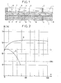
- the plates have a height of 175 mm.
- a microporous PVC separator 7, disposed against the negative plate 1, has ribs 9 parallel to each other on its face facing the positive plate 4; a sheet of glass wool 12 is applied against the positive plate 4 and a microporous PVC separator 8 is interposed between the separator 7 and the sheet 12.
- the separator 8 has ribs 10 parallel to each other and parallel to the ribs 9 so as to define channels 11 (vertical in the normal position of use of the accumulator) to allow the circulation of the electrolyte.
- the separators 7 and 8 are preferably identical; the distance between two ribs 9 or 10 is approximately 10mm; the thickness of a rib 9 or 10 is of the order of 0.7 mm, the total thickness of a microporous separator is of the order of 1.5 mm, and that of the two separators 7 and 8 is around 2.25mm.
- the channels defined by the separators therefore have a thickness of the order of 0.7 mm and a width of the order of 4 mm.
- the faces 13 and 14 of the separators 7 and 8 have fine ridges parallel to each other, separated by a distance of the order of a millimeter and which may be between 0.8 mm and 1.4 mm.
- Two accumulators A and B of nominal capacity Cn are produced in 5 hours equal to 54 Ah and each comprising four negative plates 1 and three positive plates 4.
- the accumulator A according to the prior art is provided with separation means constituted by a separator 7 and a sheet of glass wool 12.
- Accumulator B according to the invention is constructed according to the diagram in FIG. 1.
- the curves A and B relating to the accumulators A and B represent the variations in the capacity C in ampere-hours as a function of the number of cycles N.
- the curve B stops at 1000 cycles, but the tests continue. We can already see the progress made by the structure of Figure 1 from the point of view of the endurance of the battery.
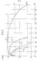
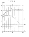
- Curves D and E 1 of FIG. 3 confirm the advantage of the separation means of FIG. 1 associated with that of the binding binder of the positive active material from the point of view of endurance.
- the accumulators E 2 and E 3 have the same arrangement as the accumulator E 1 but they differ from it by the dimensions of the channels defined by their separators. Thus, for E 2 the thickness of a channel is 0.35 mm and its width is 4 mm; for E 3 the thickness of a channel is 0.7 mm and its width 11 mm.
- the curves E 2 and E 3 in FIG. 2 clearly show the deterioration in the performance of the accumulator when the dimensions of the channels come out of the ranges provided according to the invention.
- Two accumulators F and G are produced, analogous respectively to accumulators D and E 1 but in which a device for forced electrolyte circulation is provided, with a flow rate of a few liters per hour.
- the curves F and G of the same type as the curves of FIGS. 2 and 3 illustrate the improvement in the endurance resistance of the accumulators when all the elements of the invention are combined.
- the invention is not limited to the examples which have just been described.
- the two microporous separators applied respectively against the positive and negative plates oppose the swelling of the active materials, the channels of thickness greater than 0.5 mm which they define ensure the homogenization of the electrolyte concentrations and their streaks favor the evacuation of gases.
Landscapes
- Manufacturing & Machinery (AREA)
- Chemical & Material Sciences (AREA)
- Chemical Kinetics & Catalysis (AREA)
- Electrochemistry (AREA)
- General Chemical & Material Sciences (AREA)
- Engineering & Computer Science (AREA)
- Cell Separators (AREA)
- Secondary Cells (AREA)
- Organic Insulating Materials (AREA)
- Supply Devices, Intensifiers, Converters, And Telemotors (AREA)
- Filling, Topping-Up Batteries (AREA)
- Valve Device For Special Equipments (AREA)
- Liquid Developers In Electrophotography (AREA)
- Vessels And Coating Films For Discharge Lamps (AREA)
Priority Applications (1)
| Application Number | Priority Date | Filing Date | Title |
|---|---|---|---|
| AT80400985T ATE9630T1 (de) | 1979-07-04 | 1980-06-30 | Elektrischer blei-akkumulator. |
Applications Claiming Priority (2)
| Application Number | Priority Date | Filing Date | Title |
|---|---|---|---|
| FR7917384A FR2460546A1 (fr) | 1979-07-04 | 1979-07-04 | Accumulateur electrique au plomb |
| FR7917384 | 1979-07-04 |
Publications (2)
| Publication Number | Publication Date |
|---|---|
| EP0022402A1 true EP0022402A1 (de) | 1981-01-14 |
| EP0022402B1 EP0022402B1 (de) | 1984-09-26 |
Family
ID=9227510
Family Applications (1)
| Application Number | Title | Priority Date | Filing Date |
|---|---|---|---|
| EP80400985A Expired EP0022402B1 (de) | 1979-07-04 | 1980-06-30 | Elektrischer Blei-Akkumulator |
Country Status (10)
| Country | Link |
|---|---|
| US (1) | US4360576A (de) |
| EP (1) | EP0022402B1 (de) |
| JP (1) | JPS56500788A (de) |
| AT (1) | ATE9630T1 (de) |
| CA (1) | CA1139836A (de) |
| DE (1) | DE3069283D1 (de) |
| ES (1) | ES493066A0 (de) |
| FR (1) | FR2460546A1 (de) |
| IE (1) | IE50140B1 (de) |
| WO (1) | WO1981000176A1 (de) |
Cited By (1)
| Publication number | Priority date | Publication date | Assignee | Title |
|---|---|---|---|---|
| EP0066938A3 (en) * | 1981-06-01 | 1984-04-25 | Exxon Research And Engineering Company | Separator-spacer, electrode, and use thereof in electrochemical systems |
Families Citing this family (5)
| Publication number | Priority date | Publication date | Assignee | Title |
|---|---|---|---|---|
| US4927722A (en) * | 1988-09-09 | 1990-05-22 | Grace G.M.B.H. | Separator for starter batteries |
| US4955377A (en) * | 1988-10-28 | 1990-09-11 | Lennox Charles D | Device and method for heating tissue in a patient's body |
| US5191883A (en) * | 1988-10-28 | 1993-03-09 | Prutech Research And Development Partnership Ii | Device for heating tissue in a patient's body |
| US5288565A (en) * | 1993-02-08 | 1994-02-22 | Globe-Union Inc. | Support extension for flat pack rechargeable batteries |
| WO2003070298A2 (en) | 2002-02-15 | 2003-08-28 | Celsion Corporation | Method and apparatus treating tissue adjacent a bodily conduit with thermocompression and drugs |
Citations (10)
| Publication number | Priority date | Publication date | Assignee | Title |
|---|---|---|---|---|
| US2004304A (en) * | 1933-08-01 | 1935-06-11 | Willard Storage Battery Co | Storage battery separator |
| US2422130A (en) * | 1944-01-14 | 1947-06-10 | Edison Inc Thomas A | Storage battery plate and separator assembly |
| FR951761A (fr) * | 1945-03-14 | 1949-11-03 | Owens Corning Fiberglass Corp | Perfectionnements aux séparateurs pour plaques d'accumulateurs |
| FR1045872A (fr) * | 1951-07-10 | 1953-12-01 | Owens Corning Fiberglass Corp | Séparateur pour plaques de batteries d'accumulateurs |
| US2742521A (en) * | 1951-12-21 | 1956-04-17 | Joseph C Duddy | Storage battery separator |
| FR1154599A (fr) * | 1955-07-20 | 1958-04-11 | Pritchett & Gold & E P S Co | élément séparateur pour batterie d'accumulateurs électriques et batterie d'accumulateurs électriques comportant ledit élément |
| US2909588A (en) * | 1953-01-05 | 1959-10-20 | Electric Storage Battery Co | Storage battery separator |
| FR1243515A (fr) * | 1959-09-03 | 1960-10-14 | Cie De Caoutchouc Manufacture | Perfectionnement aux séparateurs pour accumulateurs |
| US3898099A (en) * | 1974-03-18 | 1975-08-05 | Energy Res Corp | Hydrophilic electrode and method for making the same |
| FR2266318A1 (en) * | 1974-03-26 | 1975-10-24 | Europ Accumulateurs | Electric accumulator cell - has sheathed positive plate held against active material by grooved separator |
Family Cites Families (8)
| Publication number | Priority date | Publication date | Assignee | Title |
|---|---|---|---|---|
| US1644590A (en) * | 1923-03-05 | 1927-10-04 | Philadelphia Storage Battery | Storage battery |
| FR761725A (fr) * | 1933-10-06 | 1934-03-26 | Perfectionnements aux batteries d'accumulateurs électriques | |
| US2465493A (en) * | 1944-12-05 | 1949-03-29 | Us Rubber Co | Embossed battery separator |
| US2607810A (en) * | 1950-03-22 | 1952-08-19 | Owens Corning Fiberglass Corp | Storage battery plate separator |
| US2925456A (en) * | 1956-05-14 | 1960-02-16 | Accumulatorenfabriek Varta N V | Separator for electric accumulators |
| US3350484A (en) * | 1965-03-01 | 1967-10-31 | Riegel Paper Corp | Method and apparatus for making battery separators and the like |
| BE842455A (fr) * | 1975-06-06 | 1976-10-01 | Dispositif de batterie a plaques depolarisees | |
| US4245013A (en) * | 1978-05-11 | 1981-01-13 | Chloride Group Limited | Battery separators |
-
1979
- 1979-07-04 FR FR7917384A patent/FR2460546A1/fr active Granted
-
1980
- 1980-06-30 JP JP50141380A patent/JPS56500788A/ja active Pending
- 1980-06-30 DE DE8080400985T patent/DE3069283D1/de not_active Expired
- 1980-06-30 AT AT80400985T patent/ATE9630T1/de active
- 1980-06-30 US US06/230,960 patent/US4360576A/en not_active Expired - Fee Related
- 1980-06-30 EP EP80400985A patent/EP0022402B1/de not_active Expired
- 1980-06-30 WO PCT/FR1980/000104 patent/WO1981000176A1/fr not_active Ceased
- 1980-07-03 IE IE1384/80A patent/IE50140B1/en unknown
- 1980-07-03 CA CA000355390A patent/CA1139836A/fr not_active Expired
- 1980-07-03 ES ES493066A patent/ES493066A0/es active Granted
Patent Citations (10)
| Publication number | Priority date | Publication date | Assignee | Title |
|---|---|---|---|---|
| US2004304A (en) * | 1933-08-01 | 1935-06-11 | Willard Storage Battery Co | Storage battery separator |
| US2422130A (en) * | 1944-01-14 | 1947-06-10 | Edison Inc Thomas A | Storage battery plate and separator assembly |
| FR951761A (fr) * | 1945-03-14 | 1949-11-03 | Owens Corning Fiberglass Corp | Perfectionnements aux séparateurs pour plaques d'accumulateurs |
| FR1045872A (fr) * | 1951-07-10 | 1953-12-01 | Owens Corning Fiberglass Corp | Séparateur pour plaques de batteries d'accumulateurs |
| US2742521A (en) * | 1951-12-21 | 1956-04-17 | Joseph C Duddy | Storage battery separator |
| US2909588A (en) * | 1953-01-05 | 1959-10-20 | Electric Storage Battery Co | Storage battery separator |
| FR1154599A (fr) * | 1955-07-20 | 1958-04-11 | Pritchett & Gold & E P S Co | élément séparateur pour batterie d'accumulateurs électriques et batterie d'accumulateurs électriques comportant ledit élément |
| FR1243515A (fr) * | 1959-09-03 | 1960-10-14 | Cie De Caoutchouc Manufacture | Perfectionnement aux séparateurs pour accumulateurs |
| US3898099A (en) * | 1974-03-18 | 1975-08-05 | Energy Res Corp | Hydrophilic electrode and method for making the same |
| FR2266318A1 (en) * | 1974-03-26 | 1975-10-24 | Europ Accumulateurs | Electric accumulator cell - has sheathed positive plate held against active material by grooved separator |
Cited By (1)
| Publication number | Priority date | Publication date | Assignee | Title |
|---|---|---|---|---|
| EP0066938A3 (en) * | 1981-06-01 | 1984-04-25 | Exxon Research And Engineering Company | Separator-spacer, electrode, and use thereof in electrochemical systems |
Also Published As
| Publication number | Publication date |
|---|---|
| CA1139836A (fr) | 1983-01-18 |
| US4360576A (en) | 1982-11-23 |
| IE801384L (en) | 1981-01-04 |
| WO1981000176A1 (fr) | 1981-01-22 |
| ES8200514A1 (es) | 1981-11-01 |
| ATE9630T1 (de) | 1984-10-15 |
| DE3069283D1 (en) | 1984-10-31 |
| JPS56500788A (de) | 1981-06-11 |
| ES493066A0 (es) | 1981-11-01 |
| FR2460546A1 (fr) | 1981-01-23 |
| EP0022402B1 (de) | 1984-09-26 |
| IE50140B1 (en) | 1986-02-19 |
| FR2460546B1 (de) | 1984-01-06 |
Similar Documents
| Publication | Publication Date | Title |
|---|---|---|
| CN103620852B (zh) | 电极组件、以及电池单元和包括其的装置 | |
| KR101575984B1 (ko) | 전극탭 접합성이 우수한 전극 조립체, 이를 포함하는 전지셀, 디바이스 및 이의 제조방법 | |
| CN209312928U (zh) | 电极组件 | |
| EP3014676A1 (de) | Streifen aus elektrochemischen zellen zur herstellung eines batteriemoduls für ein elektro- oder hybridfahrzeug und verfahren zur herstellung von solch einem modul | |
| EP3020081B1 (de) | Modul mit mehreren entfernbaren zellen, batterie mit solch einem modul und fahrzeug mit solch einer batterie | |
| EP0402265B1 (de) | Verschlossene Bleiakkumulatorbatterie mit bipolaren Elektroden | |
| EP0310075A2 (de) | Aktivierbarer elektrochemischer Lithium-Oxyhalogenid-Generator | |
| WO2017089454A1 (fr) | Batterie bipolaire lithium-ion | |
| EP0022402B1 (de) | Elektrischer Blei-Akkumulator | |
| KR102464824B1 (ko) | 전지 모듈 및 이를 포함하는 전지 팩 | |
| US9281548B2 (en) | Battery module for mitigating gas accumulation and methods thereof | |
| KR102737302B1 (ko) | 이차 전지 및 이를 포함하는 디바이스 | |
| KR20150134660A (ko) | 계단 구조의 복합 전극 조립체 | |
| KR101569055B1 (ko) | 출력 및 용량 특성이 다른 전극들을 포함하고 있는 하이브리드형 이차전지 | |
| EP3327818B1 (de) | Metallionen batterie mit einem elektrodenstapel aufweisend hohe kapazität und hohe leistung | |
| FR3023416A3 (fr) | Module de batterie a assemblage simplifie | |
| KR101654800B1 (ko) | 냉각구조가 형성된 이차전지모듈 | |
| KR100889524B1 (ko) | 배터리 | |
| JP2021516849A (ja) | 圧電素子および熱電素子を含む円筒形二次電池 | |
| KR102930254B1 (ko) | 이차 전지 및 이를 포함하는 디바이스 | |
| EP3840103B1 (de) | Elektrochemischer akku, insbesondere metall-ionen-akku, mit weicher verpackung, die kühlkanäle umfasst, entsprechendes modul und entsprechendes herstellungsverfahren | |
| KR20220133021A (ko) | 전지 팩 및 이를 포함하는 디바이스 | |
| EP3327819B1 (de) | Metallionen-akkumulator mit einem stapel elektroden, gekennzeichnet durch eine hohe energiedichte und eine hohe kapazität | |
| US2213850A (en) | Battery plate | |
| WO2025257418A1 (fr) | Bloc de batteries d'accumulateurs électriques |
Legal Events
| Date | Code | Title | Description |
|---|---|---|---|
| PUAI | Public reference made under article 153(3) epc to a published international application that has entered the european phase |
Free format text: ORIGINAL CODE: 0009012 |
|
| AK | Designated contracting states |
Designated state(s): AT BE CH DE FR GB IT LU NL SE |
|
| 17P | Request for examination filed |
Effective date: 19810619 |
|
| ITF | It: translation for a ep patent filed | ||
| GRAA | (expected) grant |
Free format text: ORIGINAL CODE: 0009210 |
|
| AK | Designated contracting states |
Designated state(s): AT BE CH DE FR GB IT LI LU NL SE |
|
| REF | Corresponds to: |
Ref document number: 9630 Country of ref document: AT Date of ref document: 19841015 Kind code of ref document: T |
|
| REF | Corresponds to: |
Ref document number: 3069283 Country of ref document: DE Date of ref document: 19841031 |
|
| PGFP | Annual fee paid to national office [announced via postgrant information from national office to epo] |
Ref country code: AT Payment date: 19850617 Year of fee payment: 6 |
|
| PG25 | Lapsed in a contracting state [announced via postgrant information from national office to epo] |
Ref country code: LU Free format text: LAPSE BECAUSE OF NON-PAYMENT OF DUE FEES Effective date: 19850630 |
|
| PGFP | Annual fee paid to national office [announced via postgrant information from national office to epo] |
Ref country code: NL Payment date: 19850630 Year of fee payment: 6 |
|
| PLBE | No opposition filed within time limit |
Free format text: ORIGINAL CODE: 0009261 |
|
| STAA | Information on the status of an ep patent application or granted ep patent |
Free format text: STATUS: NO OPPOSITION FILED WITHIN TIME LIMIT |
|
| 26N | No opposition filed | ||
| PG25 | Lapsed in a contracting state [announced via postgrant information from national office to epo] |
Ref country code: LI Effective date: 19860630 Ref country code: CH Effective date: 19860630 Ref country code: BE Effective date: 19860630 Ref country code: AT Effective date: 19860630 |
|
| PG25 | Lapsed in a contracting state [announced via postgrant information from national office to epo] |
Ref country code: SE Effective date: 19860701 |
|
| BERE | Be: lapsed |
Owner name: CIE GENERALE D'ELECTRICITE Effective date: 19860630 |
|
| PG25 | Lapsed in a contracting state [announced via postgrant information from national office to epo] |
Ref country code: NL Effective date: 19870101 |
|
| NLV4 | Nl: lapsed or anulled due to non-payment of the annual fee | ||
| PG25 | Lapsed in a contracting state [announced via postgrant information from national office to epo] |
Ref country code: FR Free format text: LAPSE BECAUSE OF NON-PAYMENT OF DUE FEES Effective date: 19870227 |
|
| REG | Reference to a national code |
Ref country code: CH Ref legal event code: PL |
|
| PG25 | Lapsed in a contracting state [announced via postgrant information from national office to epo] |
Ref country code: DE Effective date: 19870303 |
|
| GBPC | Gb: european patent ceased through non-payment of renewal fee | ||
| REG | Reference to a national code |
Ref country code: FR Ref legal event code: ST |
|
| PG25 | Lapsed in a contracting state [announced via postgrant information from national office to epo] |
Ref country code: GB Effective date: 19881118 |
|
| EUG | Se: european patent has lapsed |
Ref document number: 80400985.0 Effective date: 19870518 |