EP0021972A1 - Automate de manipulation précise à cadence élevée - Google Patents
Automate de manipulation précise à cadence élevée Download PDFInfo
- Publication number
- EP0021972A1 EP0021972A1 EP80400873A EP80400873A EP0021972A1 EP 0021972 A1 EP0021972 A1 EP 0021972A1 EP 80400873 A EP80400873 A EP 80400873A EP 80400873 A EP80400873 A EP 80400873A EP 0021972 A1 EP0021972 A1 EP 0021972A1
- Authority
- EP
- European Patent Office
- Prior art keywords
- precise
- displacement
- zones
- zone
- fixed
- Prior art date
- Legal status (The legal status is an assumption and is not a legal conclusion. Google has not performed a legal analysis and makes no representation as to the accuracy of the status listed.)
- Ceased
Links
- 238000006073 displacement reaction Methods 0.000 claims abstract description 19
- 238000004519 manufacturing process Methods 0.000 description 3
- 238000012935 Averaging Methods 0.000 description 2
- 238000010586 diagram Methods 0.000 description 2
- 239000012530 fluid Substances 0.000 description 1
- 238000009776 industrial production Methods 0.000 description 1
- 238000003754 machining Methods 0.000 description 1
- 230000007246 mechanism Effects 0.000 description 1
- 238000010587 phase diagram Methods 0.000 description 1
Images


Classifications
-
- B—PERFORMING OPERATIONS; TRANSPORTING
- B23—MACHINE TOOLS; METAL-WORKING NOT OTHERWISE PROVIDED FOR
- B23P—METAL-WORKING NOT OTHERWISE PROVIDED FOR; COMBINED OPERATIONS; UNIVERSAL MACHINE TOOLS
- B23P19/00—Machines for simply fitting together or separating metal parts or objects, or metal and non-metal parts, whether or not involving some deformation; Tools or devices therefor so far as not provided for in other classes
- B23P19/10—Aligning parts to be fitted together
-
- B—PERFORMING OPERATIONS; TRANSPORTING
- B23—MACHINE TOOLS; METAL-WORKING NOT OTHERWISE PROVIDED FOR
- B23Q—DETAILS, COMPONENTS, OR ACCESSORIES FOR MACHINE TOOLS, e.g. ARRANGEMENTS FOR COPYING OR CONTROLLING; MACHINE TOOLS IN GENERAL CHARACTERISED BY THE CONSTRUCTION OF PARTICULAR DETAILS OR COMPONENTS; COMBINATIONS OR ASSOCIATIONS OF METAL-WORKING MACHINES, NOT DIRECTED TO A PARTICULAR RESULT
- B23Q7/00—Arrangements for handling work specially combined with or arranged in, or specially adapted for use in connection with, machine tools, e.g. for conveying, loading, positioning, discharging, sorting
- B23Q7/04—Arrangements for handling work specially combined with or arranged in, or specially adapted for use in connection with, machine tools, e.g. for conveying, loading, positioning, discharging, sorting by means of grippers
- B23Q7/046—Handling workpieces or tools
-
- B—PERFORMING OPERATIONS; TRANSPORTING
- B25—HAND TOOLS; PORTABLE POWER-DRIVEN TOOLS; MANIPULATORS
- B25J—MANIPULATORS; CHAMBERS PROVIDED WITH MANIPULATION DEVICES
- B25J9/00—Programme-controlled manipulators
-
- B—PERFORMING OPERATIONS; TRANSPORTING
- B25—HAND TOOLS; PORTABLE POWER-DRIVEN TOOLS; MANIPULATORS
- B25J—MANIPULATORS; CHAMBERS PROVIDED WITH MANIPULATION DEVICES
- B25J9/00—Programme-controlled manipulators
- B25J9/02—Programme-controlled manipulators characterised by movement of the arms, e.g. cartesian coordinate type
- B25J9/023—Cartesian coordinate type
-
- B—PERFORMING OPERATIONS; TRANSPORTING
- B25—HAND TOOLS; PORTABLE POWER-DRIVEN TOOLS; MANIPULATORS
- B25J—MANIPULATORS; CHAMBERS PROVIDED WITH MANIPULATION DEVICES
- B25J9/00—Programme-controlled manipulators
- B25J9/10—Programme-controlled manipulators characterised by positioning means for manipulator elements
- B25J9/1005—Programme-controlled manipulators characterised by positioning means for manipulator elements comprising adjusting means
- B25J9/1015—Programme-controlled manipulators characterised by positioning means for manipulator elements comprising adjusting means using additional, e.g. microadjustment of the end effector
Definitions
- the present invention relates to a precise handling machine at high speed, for example intended to handle parts or tools.
- Such automata are currently finding an increasingly widespread use in the fields of assembly and machining, for example in the production of automatic assembly lines in small mechanics. In the latter case in particular, such automata operate according to a rigid sequence of functions for picking up the piece, moving, removing, screwing, riveting, bonding, etc.
- Automata of this type are already known, having a fixed or programmable stroke, but, generally, in these known automata, the final positioning precision is obtained at the expense of the rate, because it is difficult to have a system with high speed, great stroke and good accuracy.
- each known automaton of this type is rigidly limited to mounting or mass production of a single complex product. It is therefore economically impossible to use such an automaton for small or medium series, which nevertheless represent the largest part of industrial production.
- the object of the present invention is to remedy these drawbacks. It concerns an automaton allowing rapid movements and long strokes, with very high precision.
- the automatic device according to the invention is easily reconfigurable for switching from one type of product to another, by simply modifying the devices for distributing the components and changing the working accessories and its system of control is very flexible to allow switching, by programming, from one product model to another within the same family of products.
- the automaton is particularly suitable for the automatic mounting of small mechanisms, since such an assembly requires, on the one hand, very short cycle times, for the profitability of the equipment, because of the low unit price of the product to be assembled and, on the other hand, a very precise positioning (often better than a tenth of a mm), because of the small dimensions of the parts to be assembled.
- the fast and precise automaton for the alternating movement of an active member between, on the one hand, any position chosen from among a plurality of possible positions of a first zone and, on the other hand, any position chosen from a plurality of possible positions of a second zone, distant from the first is remarkable in that it comprises means of displacement with fixed travel between a determined point in one of said zones and a determined point on the other of said zones, as well as precise displacement means, 'associated with displacement means with fixed stroke and slaved in position to cause said active member to perform, during displacement with fixed stroke, the short path which would separate the selected positions of the first and second zones, if these zones, following the movement at high speed had been brought into superposition so that their determined points are superimposed.
- control of the precise movement means is carried out using setpoint values formed by the average of the position parameter values actually reached during previous identical cycles. This avoids any drift.
- Figures 1 and 2 schematically illustrate, in connection with an exemplary implementation, the operation of the automatic device according to the invention.
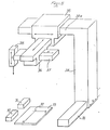
- FIG. 3 shows an exemplary embodiment of the automaton intended to produce the exemplary implementation of FIGS. 1 and 2.
- FIGS. 4a, 4b and 4c are phase diagrams of the various actuators of the automaton of FIG. 3.
- FIG. 5 schematically illustrates another automaton according to the invention, intended for another application.
- a zone 1 for gripping parts comprising a plurality of gripping locations 2, as well as a zone 3 for assembling parts, comprising a plurality of assembly locations 4.
- the respective centers 5 and 6 of zones 1 and 3 are distant from D.
- high-speed displacement means capable of causing the support of the active member to carry out a rectilinear translation of amplitude D.
- this translation everything takes place as if the gripping zone 1 had been brought into superposition on the assembly zone 3, so that the centers 5 and 6 are superimposed, as shown in FIG. 2.
- the active member in addition to the translation D, to pass from position 2 'to position 4 ', it is necessary to make the active member perform a rotation of amplitude 6 and a radial displacement of amplitude l.
- the passage of the active member from position 2 ′ to position 4 ′ is effected by the superposition of the translation D at high speed, of the precise rotation 6 and of the precise radial translation, l, the precise rotation 6 and the precise radial translation l being controlled and carried out during the translation D at high speed.
- the functions "high speed movement over a possibly large stroke” and “precise positioning for limited movements” are carried out separately, by independent means and having their own characteristics which are hardly compatible when they are demanded in the same way.
- the movement at high speed is for example programmed (in open loop) and it can ensure coarse positioning, for example to within 0.5 mm.
- the precise movement is controlled (in closed loop) mechanically, optically, hydraulically, piezoelectrically, etc. (not shown).
- the automatic device according to the invention comprises a frame 10 on which is fixed a rapid hydraulic cylinder 11.
- the rod 12 of the cylinder 11 is integral with a carriage 13 which can slide between a front stop 14 and a rear stop 15, thanks to two parallel rods 16 integral with said carriage, and passing in sliding bearings 17 integral with the frame l.
- the stroke of the carriage 13 between the stops 14 and 15 corresponds to the stroke D of FIG. 1.
- a precise rotary actuator 17 intended to rotate a crew 18 relative to said carriage.
- the rotary actuator 17 provides the angular displacement 8 of FIG. 2.
- a precise cylinder 19 intended to actuate the active member 20 in sliding (for example a gripping member) along the radial path l in FIG. 2.
- the different cylinders are connected by appropriate connections 21 to 25 to sources of electric current or pressurized fluid.
- a servo device 26 controls the rotary actuator 17 to a set value ⁇ o and the actuator 19 to a set value l o .
- the setpoints 6 and l o are either programmed, or indicated by "learning", or even result from the averaging of a plurality of previous setting values 6 and l.
- Diagrams 4a to 4c illustrate the operation of the device in FIG. 2 as a function of time t.
- the jacks 11, 17 and 19 are actuated simultaneously, so that the speed V 12 of the rod 12 (stroke D ) increases from zero between t o and t 1 and between t 1 and t 2 ' then is constant from t 2 to t 3 , to decrease rapidly from t 3 to t 4 , then less rapidly to 0 from t 4 to t f , t f being the moment at which the member 20 must be in line with the position 4 '(see FIG. 4a).
- the rod 12 and therefore the carriage 13 have traveled the distance D.
- the actuation of the jacks 17 and 19 also begins at time t o to end at time t 5 before t f . It can therefore be seen that the precise positioning of the member 20 is controlled during the high speed and long stroke displacement of the rod 12 and is completed before the end of this displacement. Thus, the precise positioning of the member 20 can be obtained before the carriage 13 arrives on the "stop 14.
- the position of the member 10 is programmable so that the starting or finishing points 2 or arrival or starting points 4 can be chosen according to production requirements.
- the setpoints ⁇ o and l o can be self-adapted during identical successive cycles by averaging the last positions actually obtained.
- FIG. 5 illustrates another exemplary embodiment intended to take parts alternately from two magazines 30 and 31, to assemble them to the point 32 of a mounting plate 33.
- This embodiment comprises a gantry 34, which can slide horizontally from a rapid displacement with a fixed stroke, along a guide device 35.
- the gantry 34 carries on a horizontal branch 34a, a carriage fast with fixed horizontal stroke 35, of sliding direction orthogonal to that of the gantry.
- On the carriage 35 is mounted a carriage 36 with precise and programmed movement in a horizontal direction orthogonal to that of the carriage 35, and on the carriage 36 is mounted on a carriage 37 with precise and programmed movement of horizontal direction orthogonal to that of the carriage 36.
- a carriage 38 On the carriage 37 is mounted a carriage 38, movable vertically and carrying the gripping member.
Landscapes
- Engineering & Computer Science (AREA)
- Mechanical Engineering (AREA)
- Robotics (AREA)
- Automatic Assembly (AREA)
Applications Claiming Priority (2)
| Application Number | Priority Date | Filing Date | Title |
|---|---|---|---|
| FR7915352 | 1979-06-15 | ||
| FR7915352A FR2459111A1 (fr) | 1979-06-15 | 1979-06-15 | Automate de manipulation precise a cadence elevee |
Publications (1)
| Publication Number | Publication Date |
|---|---|
| EP0021972A1 true EP0021972A1 (fr) | 1981-01-07 |
Family
ID=9226660
Family Applications (1)
| Application Number | Title | Priority Date | Filing Date |
|---|---|---|---|
| EP80400873A Ceased EP0021972A1 (fr) | 1979-06-15 | 1980-06-16 | Automate de manipulation précise à cadence élevée |
Country Status (2)
| Country | Link |
|---|---|
| EP (1) | EP0021972A1 (OSRAM) |
| FR (1) | FR2459111A1 (OSRAM) |
Cited By (12)
| Publication number | Priority date | Publication date | Assignee | Title |
|---|---|---|---|---|
| FR2508362A1 (fr) * | 1981-06-24 | 1982-12-31 | Sony Corp | Machine automatique d'assemblage |
| EP0102575A1 (en) * | 1982-08-25 | 1984-03-14 | Hitachi, Ltd. | Pick and place unit |
| EP0139781A1 (de) * | 1983-10-28 | 1985-05-08 | Fürstlich Hohenzollernsche Hüttenverwaltung Laucherthal | Handhabungsgerät |
| FR2562828A1 (fr) * | 1984-04-12 | 1985-10-18 | Aerospatiale | Procede et dispositif de positionnement automatique d'un outil de travail par rapport a une piece |
| FR2564021A1 (fr) * | 1984-05-10 | 1985-11-15 | Havre Chantiers | Dispositif autoguide pour le positionnement des machines-outils robotisees |
| EP0283403A1 (fr) * | 1987-03-20 | 1988-09-21 | R.G.D. S.A. | Automate manipulateur programmable pour la desserte d'une machine-outil |
| EP0251814A3 (en) * | 1986-07-04 | 1989-08-23 | Engraving Developments Ltd | Engraving machine |
| FR2630675A1 (fr) * | 1988-05-02 | 1989-11-03 | Aerospatiale | Systeme pour realiser des operations sur des objets de grandes dimensions, notamment pour peindre un aeronef |
| EP0961118A3 (de) * | 1998-05-25 | 2003-05-21 | Abbott GmbH & Co. KG | Pipettierautomat |
| EP1366846A1 (en) * | 2002-05-28 | 2003-12-03 | Trumpf, Inc. | Laser cutting machine with two y-axis drives |
| CN104801622A (zh) * | 2015-04-20 | 2015-07-29 | 广东工业大学 | 用于确定冲压生产线自动拾取工件最佳位置的方法及装置 |
| CN107825125A (zh) * | 2017-11-30 | 2018-03-23 | 中国地质大学(武汉) | 一种基于视觉伺服的螺孔定位及锁卸螺丝装置 |
Families Citing this family (1)
| Publication number | Priority date | Publication date | Assignee | Title |
|---|---|---|---|---|
| DE3303588A1 (de) * | 1982-02-03 | 1983-08-11 | Volkswagenwerk Ag, 3180 Wolfsburg | Einrichtung zur automatischen betaetigung von bedienungshebeln eines kraftfahrzeugs auf einem rollenpruefstand |
Citations (3)
| Publication number | Priority date | Publication date | Assignee | Title |
|---|---|---|---|---|
| FR1365562A (fr) * | 1963-06-13 | 1964-07-03 | Festo Maschf Stoll G | Dispositif de positionnement et de transport de pièces |
| US3306471A (en) * | 1964-05-19 | 1967-02-28 | George C Devol | Programmed apparatus |
| GB2009353A (en) * | 1977-11-26 | 1979-06-13 | Schlatter Ag | Improvements in or relating to industrial robots |
-
1979
- 1979-06-15 FR FR7915352A patent/FR2459111A1/fr active Granted
-
1980
- 1980-06-16 EP EP80400873A patent/EP0021972A1/fr not_active Ceased
Patent Citations (3)
| Publication number | Priority date | Publication date | Assignee | Title |
|---|---|---|---|---|
| FR1365562A (fr) * | 1963-06-13 | 1964-07-03 | Festo Maschf Stoll G | Dispositif de positionnement et de transport de pièces |
| US3306471A (en) * | 1964-05-19 | 1967-02-28 | George C Devol | Programmed apparatus |
| GB2009353A (en) * | 1977-11-26 | 1979-06-13 | Schlatter Ag | Improvements in or relating to industrial robots |
Cited By (15)
| Publication number | Priority date | Publication date | Assignee | Title |
|---|---|---|---|---|
| FR2508362A1 (fr) * | 1981-06-24 | 1982-12-31 | Sony Corp | Machine automatique d'assemblage |
| EP0102575A1 (en) * | 1982-08-25 | 1984-03-14 | Hitachi, Ltd. | Pick and place unit |
| EP0139781A1 (de) * | 1983-10-28 | 1985-05-08 | Fürstlich Hohenzollernsche Hüttenverwaltung Laucherthal | Handhabungsgerät |
| FR2562828A1 (fr) * | 1984-04-12 | 1985-10-18 | Aerospatiale | Procede et dispositif de positionnement automatique d'un outil de travail par rapport a une piece |
| EP0159269A1 (fr) * | 1984-04-12 | 1985-10-23 | AEROSPATIALE Société Nationale Industrielle | Procédé et dispositif de positionnement atutomatique d'une outil de travail par rapport à une pièce |
| FR2564021A1 (fr) * | 1984-05-10 | 1985-11-15 | Havre Chantiers | Dispositif autoguide pour le positionnement des machines-outils robotisees |
| EP0251814A3 (en) * | 1986-07-04 | 1989-08-23 | Engraving Developments Ltd | Engraving machine |
| EP0283403A1 (fr) * | 1987-03-20 | 1988-09-21 | R.G.D. S.A. | Automate manipulateur programmable pour la desserte d'une machine-outil |
| FR2612443A1 (fr) * | 1987-03-20 | 1988-09-23 | Rgd Sa | Automate manipulateur programmable pour la desserte d'une machine-outil |
| FR2630675A1 (fr) * | 1988-05-02 | 1989-11-03 | Aerospatiale | Systeme pour realiser des operations sur des objets de grandes dimensions, notamment pour peindre un aeronef |
| EP0341134A1 (fr) * | 1988-05-02 | 1989-11-08 | AEROSPATIALE Société Nationale Industrielle | Système pour réaliser des opérations sur des objets de grandes dimensions, notamment pour peindre un aéronef |
| EP0961118A3 (de) * | 1998-05-25 | 2003-05-21 | Abbott GmbH & Co. KG | Pipettierautomat |
| EP1366846A1 (en) * | 2002-05-28 | 2003-12-03 | Trumpf, Inc. | Laser cutting machine with two y-axis drives |
| CN104801622A (zh) * | 2015-04-20 | 2015-07-29 | 广东工业大学 | 用于确定冲压生产线自动拾取工件最佳位置的方法及装置 |
| CN107825125A (zh) * | 2017-11-30 | 2018-03-23 | 中国地质大学(武汉) | 一种基于视觉伺服的螺孔定位及锁卸螺丝装置 |
Also Published As
| Publication number | Publication date |
|---|---|
| FR2459111A1 (fr) | 1981-01-09 |
| FR2459111B1 (OSRAM) | 1983-10-07 |
Similar Documents
| Publication | Publication Date | Title |
|---|---|---|
| EP0021972A1 (fr) | Automate de manipulation précise à cadence élevée | |
| EP3400399B1 (fr) | Système de génération de déplacement d'une plaque de support selon six degrés de liberté | |
| EP0076268B1 (fr) | Manipulateur automatique | |
| EP2816723B1 (fr) | Mécanisme tripode à actionneurs piézoélectriques | |
| FR2519690A1 (fr) | Dispositif d'asservissement electro-hydraulique de bras-support articule pour glissiere d'appareil de foration | |
| FR2639860A1 (fr) | Dispositif de marquage par micro-percussion | |
| EP1872892A1 (fr) | Procédé et installation de mise en oeuvre d'électrodes de soudage par points | |
| FR2486434A1 (fr) | Machine-outil a commande numerique pour usiner une piece tournante | |
| FR2587318A1 (fr) | Procede et machine pour la fabrication de pieces creuses de revolution formees de fils s'etendant selon trois directions differentes. | |
| EP3209458A1 (fr) | Dispositif d'usinage vibratoire ameliore | |
| CA2557717C (fr) | Bielle a longueur evolutive en fonctionnement | |
| WO1983003643A1 (fr) | Servo-moteur hydraulique | |
| FR2659881A1 (fr) | Unite d'usinage a tete rotative portant des outils pivotants. | |
| FR2551999A1 (fr) | Machine-outil a tete rotative pour usinage de pieces fixes | |
| EP3003616B1 (fr) | Dispositif d'usinage vibratoire | |
| CA2829077A1 (fr) | Procede et dispositif de realisation de pieces, notamment de pieces de revolution allongees, par usinage d'une barre maintenue fixe en rotation | |
| FR2739801A1 (fr) | Perfectionnements aux manipulateurs plans a trajectoire figee ou programmable a tres haute cadence | |
| FR2815894A1 (fr) | Tour a commande numerique par ordinateur ayant un deplacement a vitesse double suivant l'axe de la broche | |
| EP0307293B1 (fr) | Système d'accouplement de deux corps par exemple un chariot et un poste d'usinage | |
| EP0402216A1 (fr) | Dispositif de déplacement curviligne d'un objet au contact d'une surface, notamment convexe | |
| FR2734749A1 (fr) | Manipulateur plan programmable a tres haute cadence et son support universel | |
| EP0930551B1 (fr) | Procédé de pilotage de déposé de mèches par enroulement ou au contact sur des structures de grandes dimensions et machine pour sa mise en oeuvre | |
| FR2663583A1 (fr) | Dispositif d'orientation automatique d'un outil. | |
| FR2633863A1 (fr) | Robot manipulateur a deplacement horizontal circulaire | |
| EP3515650A1 (fr) | Dispositif et procede de guidage d'un faisceau laser en deplacement rotatif et lateral pour faire varier l'excentrement du faisceau laser |
Legal Events
| Date | Code | Title | Description |
|---|---|---|---|
| PUAI | Public reference made under article 153(3) epc to a published international application that has entered the european phase |
Free format text: ORIGINAL CODE: 0009012 |
|
| AK | Designated contracting states |
Designated state(s): AT BE CH DE GB IT LU NL SE |
|
| 17P | Request for examination filed |
Effective date: 19801211 |
|
| STAA | Information on the status of an ep patent application or granted ep patent |
Free format text: STATUS: THE APPLICATION HAS BEEN REFUSED |
|
| 18R | Application refused |
Effective date: 19841014 |
|
| RIN1 | Information on inventor provided before grant (corrected) |
Inventor name: PETITEAU, MAURICE RENE |