EP0021972A1 - Precise manipulator at high cadence - Google Patents
Precise manipulator at high cadence Download PDFInfo
- Publication number
- EP0021972A1 EP0021972A1 EP80400873A EP80400873A EP0021972A1 EP 0021972 A1 EP0021972 A1 EP 0021972A1 EP 80400873 A EP80400873 A EP 80400873A EP 80400873 A EP80400873 A EP 80400873A EP 0021972 A1 EP0021972 A1 EP 0021972A1
- Authority
- EP
- European Patent Office
- Prior art keywords
- precise
- displacement
- zones
- zone
- fixed
- Prior art date
- Legal status (The legal status is an assumption and is not a legal conclusion. Google has not performed a legal analysis and makes no representation as to the accuracy of the status listed.)
- Ceased
Links
Images


Classifications
-
- B—PERFORMING OPERATIONS; TRANSPORTING
- B23—MACHINE TOOLS; METAL-WORKING NOT OTHERWISE PROVIDED FOR
- B23P—METAL-WORKING NOT OTHERWISE PROVIDED FOR; COMBINED OPERATIONS; UNIVERSAL MACHINE TOOLS
- B23P19/00—Machines for simply fitting together or separating metal parts or objects, or metal and non-metal parts, whether or not involving some deformation; Tools or devices therefor so far as not provided for in other classes
- B23P19/10—Aligning parts to be fitted together
-
- B—PERFORMING OPERATIONS; TRANSPORTING
- B23—MACHINE TOOLS; METAL-WORKING NOT OTHERWISE PROVIDED FOR
- B23Q—DETAILS, COMPONENTS, OR ACCESSORIES FOR MACHINE TOOLS, e.g. ARRANGEMENTS FOR COPYING OR CONTROLLING; MACHINE TOOLS IN GENERAL CHARACTERISED BY THE CONSTRUCTION OF PARTICULAR DETAILS OR COMPONENTS; COMBINATIONS OR ASSOCIATIONS OF METAL-WORKING MACHINES, NOT DIRECTED TO A PARTICULAR RESULT
- B23Q7/00—Arrangements for handling work specially combined with or arranged in, or specially adapted for use in connection with, machine tools, e.g. for conveying, loading, positioning, discharging, sorting
- B23Q7/04—Arrangements for handling work specially combined with or arranged in, or specially adapted for use in connection with, machine tools, e.g. for conveying, loading, positioning, discharging, sorting by means of grippers
- B23Q7/046—Handling workpieces or tools
-
- B—PERFORMING OPERATIONS; TRANSPORTING
- B25—HAND TOOLS; PORTABLE POWER-DRIVEN TOOLS; MANIPULATORS
- B25J—MANIPULATORS; CHAMBERS PROVIDED WITH MANIPULATION DEVICES
- B25J9/00—Programme-controlled manipulators
-
- B—PERFORMING OPERATIONS; TRANSPORTING
- B25—HAND TOOLS; PORTABLE POWER-DRIVEN TOOLS; MANIPULATORS
- B25J—MANIPULATORS; CHAMBERS PROVIDED WITH MANIPULATION DEVICES
- B25J9/00—Programme-controlled manipulators
- B25J9/02—Programme-controlled manipulators characterised by movement of the arms, e.g. cartesian coordinate type
- B25J9/023—Cartesian coordinate type
-
- B—PERFORMING OPERATIONS; TRANSPORTING
- B25—HAND TOOLS; PORTABLE POWER-DRIVEN TOOLS; MANIPULATORS
- B25J—MANIPULATORS; CHAMBERS PROVIDED WITH MANIPULATION DEVICES
- B25J9/00—Programme-controlled manipulators
- B25J9/10—Programme-controlled manipulators characterised by positioning means for manipulator elements
- B25J9/1005—Programme-controlled manipulators characterised by positioning means for manipulator elements comprising adjusting means
- B25J9/1015—Programme-controlled manipulators characterised by positioning means for manipulator elements comprising adjusting means using additional, e.g. microadjustment of the end effector
Landscapes
- Engineering & Computer Science (AREA)
- Mechanical Engineering (AREA)
- Robotics (AREA)
- Automatic Assembly (AREA)
Abstract
Description
La présente invention concerne un automate de mani- pulacion précise à cadence élevée, par exemple destiné à manipuler des pièces ou des outillages. De tels automates trouvent actuellement une utilisation de plus en plus étendue dans les domaines de l'assemblage et de l'usinage, par exemple dans la réalisation de chaînes d'assemblage automatique en petite mécanique. Dans ce dernier cas notamment, de tels automates fonctionnent selon une séquence rigide de fonctions de prise de pièce, de déplacement, de dépose, de vissage, de rivetage, de collage, etc...The present invention relates to a precise handling machine at high speed, for example intended to handle parts or tools. Such automata are currently finding an increasingly widespread use in the fields of assembly and machining, for example in the production of automatic assembly lines in small mechanics. In the latter case in particular, such automata operate according to a rigid sequence of functions for picking up the piece, moving, removing, screwing, riveting, bonding, etc.
On connaît déjà des automates de ce type, ayant une course fixe ou programmable, mais, généralement, dans ces automates connus, la précision finale de positionnement est obtenue au détriment de la cadence, du fait qu'il est difficile de disposer d'un système ayant une vitesse élevée, une grande course et une bonne précision. De plus, chaque automate connu de ce type est limité rigidement au montage ou à l'usinage en grande série d'un produit complexe unique. Il est donc impossible économiquement d'utiliser un tel automate pour des petites ou moyennes séries, qui représentent pourtant la plus grande partie de la production industrielle.Automata of this type are already known, having a fixed or programmable stroke, but, generally, in these known automata, the final positioning precision is obtained at the expense of the rate, because it is difficult to have a system with high speed, great stroke and good accuracy. In addition, each known automaton of this type is rigidly limited to mounting or mass production of a single complex product. It is therefore economically impossible to use such an automaton for small or medium series, which nevertheless represent the largest part of industrial production.
La présente invention a pour objet de remédier à ces inconvénients. Elle concerne un automate permettant des déplacements rapides et de grande course, avec une précision très élevée. De plus, l'automate selon l'invention est aisément reconfigurable pour passer d'un type de produit à un autre, par simple modification des dispositifs de distribution des composants et changement des accessoires de travail et son système de commande est très souple pour permettre de passer, par programmation, d'un modèle de produit à un autre à l'intérieur d'une même famille de produits.The object of the present invention is to remedy these drawbacks. It concerns an automaton allowing rapid movements and long strokes, with very high precision. In addition, the automatic device according to the invention is easily reconfigurable for switching from one type of product to another, by simply modifying the devices for distributing the components and changing the working accessories and its system of control is very flexible to allow switching, by programming, from one product model to another within the same family of products.
Ainsi, quoique non exclusivement, l'automate est particulièrement approprié au montage automatique de petits mécanismes, puisque un tel montage nécessite, d'une part, des temps de cycles très faibles, pour la rentabilisation des équipements, à cause du faible prix unitaire du produit à assembler et, d'autre part, un positionnement très précis (souvent mieux que le dixième de mm), à cause des faibles dimensions des pièces à assembler.Thus, although not exclusively, the automaton is particularly suitable for the automatic mounting of small mechanisms, since such an assembly requires, on the one hand, very short cycle times, for the profitability of the equipment, because of the low unit price of the product to be assembled and, on the other hand, a very precise positioning (often better than a tenth of a mm), because of the small dimensions of the parts to be assembled.
A cette fin, selon l'invention, l'automate rapide et précis pour le déplacement alternatif d'un organe actif entre, d'une part, une position quelconque choisie parmi une pluralité de positions possibles d'une première zone et, d'autre part, une position quelconque choisie parmi une pluralité de positions possibles d'une seconde zone, distante de la première, est remarquable en ce qu'il comporte des moyens de déplacement à course fixe entre un point déterminé de l'une desdites zones et un point déterminé de l'autre desdites zones, ainsi que des moyens de déplacement précis,'associés aux moyens de déplacement à course fixe et asservis en position pour faire effectuer audit organe actif, pendant le déplacement à course fixe, le court trajet qui séparerait les positions choisies de la première et de la seconde zones, si ces zones, à la suite du déplacement à grande vitesse avaient été amenées en superposition de façon que leurs points déterminés soient superposés.To this end, according to the invention, the fast and precise automaton for the alternating movement of an active member between, on the one hand, any position chosen from among a plurality of possible positions of a first zone and, on the other hand, any position chosen from a plurality of possible positions of a second zone, distant from the first, is remarkable in that it comprises means of displacement with fixed travel between a determined point in one of said zones and a determined point on the other of said zones, as well as precise displacement means, 'associated with displacement means with fixed stroke and slaved in position to cause said active member to perform, during displacement with fixed stroke, the short path which would separate the selected positions of the first and second zones, if these zones, following the movement at high speed had been brought into superposition so that their determined points are superimposed.
Ainsi, le déplacement rapide à grande course fixe est dissocié du déplacement précis à petite course variable et asservie, mais celui-ci s'effectue pendant le premier, de sorte que les cycles de fonctionnement peuvent être raccourcis et que la précision de positionnement est excellente.Thus, the fast movement with a large fixed stroke is dissociated from the precise movement with a small variable and controlled stroke, but the latter takes place during the first, so that the operating cycles can be shortened and the positioning accuracy is excellent.
De préférence, l'asservissement des moyens de déplacement précis est effectué à l'aide de valeurs de consignes constituées par la moyenne des valeurs de paramètres de positions réellement atteintes au cours de cycles identiques antérieurs. Ainsi, on évite toute dérive.Preferably, the control of the precise movement means is carried out using setpoint values formed by the average of the position parameter values actually reached during previous identical cycles. This avoids any drift.
Les figures du dessin annexé feront bien comprendre comment l'invention peut être réalisée.The figures of the appended drawing will make it clear how the invention can be implemented.
Les figures 1 et 2 illustrent schématiquement, à propos d'un exemple de mise en oeuvre, le fonctionnement de l'automate selon l'invention.Figures 1 and 2 schematically illustrate, in connection with an exemplary implementation, the operation of the automatic device according to the invention.
La figure 3 montre un exemple de réalisation de l'automate destiné à réaliser l'exemple de mise en oeuvre des figures 1 et 2.FIG. 3 shows an exemplary embodiment of the automaton intended to produce the exemplary implementation of FIGS. 1 and 2.
Les figures 4a, 4b et 4c sont des diagrammes de phase des différents actionneurs de l'automate de la figure 3.FIGS. 4a, 4b and 4c are phase diagrams of the various actuators of the automaton of FIG. 3.
La figure 5 illustre schématiquement un autre automate selon l'invention, destiné à une autre application.FIG. 5 schematically illustrates another automaton according to the invention, intended for another application.
Sur la figure 1, on a représenté une zone 1 de préhension de pièces, comportant une pluralité d'emplacements de préhension 2, ainsi qu'une zone 3 d'assemblage de pièces, comportant une pluralité d'emplacements d'assemblage 4. Les centres respectifs 5 et 6 des zones 1 et 3 sont distants de D.In FIG. 1, a
Pour illustrer, l'invention, on suppose qu'une pièce doit être prélevée par l'organe actif de l'automate à l'emplacement de préhension 2' de la zone 1, pour être assemblée à d'autres pièces à l'emplacement d'assemblage 4' de la zone 3.To illustrate the invention, it is assumed that a part must be removed by the active member of the automaton. at the gripping location 2 'of
Pour cela, selon l'invention, on prévoit des moyens de déplacement à grande vitesse susceptibles de faire effectuer au support de l'organe actif une translation rectiligne d'amplitude D. Dans cette translation, tout se passe comme si la zone de préhension 1 avait été amenée en superposition sur la zone d'assemblage 3,de façon que les centres 5 et 6 soient superposés, comme le montre la figure 2. Dans l'exemple décrit, outre la translation D, pour passer de la position 2' à la position 4', il est nécessaire de faire effectuer à l'organe actif une rotation d'amplitude 6 et un déplacement radial d'amplitude ℓ.For this, according to the invention, provision is made for high-speed displacement means capable of causing the support of the active member to carry out a rectilinear translation of amplitude D. In this translation, everything takes place as if the
Selon l'invention, le passage de l'organe actif de la position 2' à la position 4' s'effectue par la superposition de la translation D à grande vitesse, de la rotation précise 6 et de la translation radiale précise, ℓ, la rotation précise 6 et la translation radiale précise ℓ étant asservies et réalisées pendant la translation D à grande vitesse.According to the invention, the passage of the active member from
Ainsi, dans l'automate selon l'invention, les fonctions "déplacement à grande vitesse sur une course éventuellement grande" et "positionnement précis pour des déplacements limités" sont effectués séparément, par des moyens indépendants et possédant des caractéristiques propres difficilement compatibles lorsqu'on les exige du même moyen.Thus, in the automatic device according to the invention, the functions "high speed movement over a possibly large stroke" and "precise positioning for limited movements" are carried out separately, by independent means and having their own characteristics which are hardly compatible when they are demanded in the same way.
Bien entendu, quoique dans l'exemple des figures 1 et 2 on ait supposé que le déplacement à grande vitesse était effectué par une translation rectiligne, il va de soi que ce déplacement pourrait être obtenu par tout autre mouvement, comme par exemple circulaire. Il en est de même du déplacement précis qui peut être réalisé par tout mouvement, autre que celui résultant d'une rotation et d'une translation.Of course, although in the example of Figures 1 and 2 it was assumed that the movement at high speed was effected by a rectilinear translation, it goes from it is clear that this displacement could be obtained by any other movement, such as for example circular. It is the same for the precise movement which can be achieved by any movement, other than that resulting from a rotation and a translation.
Le déplacement à grande vitesse est par exemple programmé (en boucle ouverte) et il peut assurer un positionnement grossier, par exemple à 0,5 mm près,. En revanche, le déplacement précis est asservi (en boucle fermée) de façon mécanique, optique, hydraulique, piézoélectrique, etc... (non représentée).The movement at high speed is for example programmed (in open loop) and it can ensure coarse positioning, for example to within 0.5 mm. On the other hand, the precise movement is controlled (in closed loop) mechanically, optically, hydraulically, piezoelectrically, etc. (not shown).
Pour la réalisation du déplacement à grande vitesse, on peut utiliser un vérin de type connu à grande course de valeur fixe, commandé par tout ou rien. Pour la réalisation du positionnement précis, on utilise de préférence des actionneurs asservis légers à courses courtes.For carrying out the movement at high speed, it is possible to use a cylinder of known type with large stroke of fixed value, controlled by all or nothing. To achieve precise positioning, light servo actuators with short strokes are preferably used.
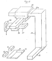
L'automate selon l'invention, représenté partiellement sur la figure 3, comporte un bâti 10 sur lequel est fixé un vérin hydraulique rapide 11. La tige 12 du vérin 11 est solidaire d'un chariot 13 pouvant coulisser entre une butée avant 14 et une butée arrière 15, grâce à deux tiges parallèles 16 solidaires dudit chariot , et passant dans des paliers de glissement 17 solidaires du bâti l.La course du chariot 13 entre les butées 14 et 15 correspond à la course D de la figure 1.The automatic device according to the invention, partially shown in FIG. 3, comprises a
A une extrémité du chariot 13 est prévu un vérin rotatif précis 17 destiné à faire tourner un équipage 18 par rapport audit chariot. Le vérin rotatif 17 fourni le déplacement angulaire 8 de la figure 2.At one end of the
De plus, sur l'équipage rotatif 18 est monté un vérin précis 19 destiné à actionner l'organe actif 20 en coulissement (par exemple un organe de préhension) selon le trajet radial ℓ de la figure 2.In addition, on the
Les différents vérins sont reliés par des liaisons appropriées 21 à 25 à des sources de courant électrique ou de fluide sous pression. De plus, un dispositif d'asservissement 26, asservit le vérin rotatif 17 à une valeur de consigne θo et le vérin 19 à une valeur de consigne ℓo. Les consignes 6 et ℓo sont soit programmées , soit indiquées par "apprentissage", soit encore résultent du moyennage d'une pluralité de valeurs de dépose 6 et ℓ antérieures.The different cylinders are connected by
Les diagrammes 4a à 4c illustrent le fonctionnement du dispositif de la figure 2 en fonction du temps t . A l'instant to, alors que l'on se trouve à l'aplomb de la position 2', les vérins 11, 17 et 19 sont actionnés simultanément, si bien que la vitesse V12 de la tige 12 (course D) croît à partir de zéro entre to et t1 et entre t1 et t2' puis est constante de t2 à t3, pour décroître rapidement de t3 à t4, puis moins rapidement jusqu'à 0 de t4 à tf, tf étant l'instant auquel l'organe 20 doit se trouver à l'aplomb de la position 4' (voir la figure 4a). Au temps tf, la tige 12 et donc le chariot 13 ont parcouru la distance D.Diagrams 4a to 4c illustrate the operation of the device in FIG. 2 as a function of time t. At time t o , while we are in line with position 2 ', the
Comme le montrent les diagrammes de la figure 4b (vitesse de rotation V6 de l'équipage mobile 18) et de la figure 4 (vitesse de déplacement Vℓ de l'organe 20) , l'actionnement des vérins 17 et 19 débute également à l'instant to pour se terminer à un instant t5 antérieur à tf. On voit donc que le positionnement précis de l'organe 20, est asservi pendant le déplacement de grande vitesse et de grande course de la tige 12 et est terminé avant la fin de ce déplacement. Ainsi, le positionnement précis de l'organe 20 peut être obtenu avant l'arrivée du chariot 13 sur la" butée 14.As shown in the diagrams in FIG. 4b (speed of rotation V 6 of the moving element 18) and of FIG. 4 (speed of movement V ℓ of the member 20), the actuation of the
Bien entendu, le mouvement de retour, de la butée 14 à la butée 15, peut s'effectuer de manière analogue.Of course, the return movement from the
On conçoit donc aisément que la position de l'organe 10 soit programmable de sorte que les points de départ ou d'arrivée 2 ou d'arrivée ou de départ 4 puissent être choisis en fonction des exigences de production.It is therefore easy to see that the position of the
Comme mentionné ci-dessus, pour compenser d'éventuelles dérives, on peut auto-adapter les consignes θo et ℓo au cours de cycles successifs identiques par moyennage des dernières positions réellement obtenues.As mentioned above, to compensate for any drifts, the setpoints θ o and ℓ o can be self-adapted during identical successive cycles by averaging the last positions actually obtained.
La présente invention n'est pas limitée à l'exemple de réalisation décrite en regard des figures 1 à 4. La figure 5 illustre un autre exemple de réalisation destiné à prélever des pièces alternativement dans deux magasins 30 et 31, pour les assembler au point 32 d'une platine de montage 33. Cette réalisation comporte un portique 34, pouvant coulisser horizontalement d'un déplacement rapide à course fixe, le long d'un dispositif de guidage 35. Le portique 34 porte sur une branche horizontale 34a, un chariot rapide à course horizontale fixe 35, de direction de coulissement orthogonale à celle du portique. Sur le chariot 35 est monté un chariot 36 à déplacement précis et programmé de direction horizontale orthogonale à celle du chariot 35, et sur le chariot 36 est monté un chariot 37 à déplacement précis et programmé de direction horizontale orthogonale à celle du chariot 36. Enfin, sur le chariot 37 est monté un chariot 38, mobile verticalement et portant l'organe de préhension.The present invention is not limited to the exemplary embodiment described with reference to FIGS. 1 to 4. FIG. 5 illustrates another exemplary embodiment intended to take parts alternately from two
Quoique les exemples précédents, on ait indiqué que les moyens asservis en position étaient montés sur les moyens à course fixe, il va de soi que l'on pourrait obtenir le résultat de l'invention en montant les moyens à course fixe sur un support ou une embase asservi en position.Although the previous examples, it was indicated that the means controlled in position were mounted on the means with fixed stroke, it goes without saying that one could obtain the result of the invention by mounting the means with fixed travel on a support or a base slaved in position.
Claims (2)
Applications Claiming Priority (2)
| Application Number | Priority Date | Filing Date | Title |
|---|---|---|---|
| FR7915352A FR2459111A1 (en) | 1979-06-15 | 1979-06-15 | ACCURATE HANDLING AUTOMATE WITH HIGH CADENCE |
| FR7915352 | 1979-06-15 |
Publications (1)
| Publication Number | Publication Date |
|---|---|
| EP0021972A1 true EP0021972A1 (en) | 1981-01-07 |
Family
ID=9226660
Family Applications (1)
| Application Number | Title | Priority Date | Filing Date |
|---|---|---|---|
| EP80400873A Ceased EP0021972A1 (en) | 1979-06-15 | 1980-06-16 | Precise manipulator at high cadence |
Country Status (2)
| Country | Link |
|---|---|
| EP (1) | EP0021972A1 (en) |
| FR (1) | FR2459111A1 (en) |
Cited By (12)
| Publication number | Priority date | Publication date | Assignee | Title |
|---|---|---|---|---|
| FR2508362A1 (en) * | 1981-06-24 | 1982-12-31 | Sony Corp | AUTOMATIC ASSEMBLY MACHINE |
| EP0102575A1 (en) * | 1982-08-25 | 1984-03-14 | Hitachi, Ltd. | Pick and place unit |
| EP0139781A1 (en) * | 1983-10-28 | 1985-05-08 | Fürstlich Hohenzollernsche Hüttenverwaltung Laucherthal | Manipulator |
| FR2562828A1 (en) * | 1984-04-12 | 1985-10-18 | Aerospatiale | METHOD AND DEVICE FOR AUTOMATICALLY POSITIONING A WORKING TOOL IN RELATION TO A WORKPIECE |
| FR2564021A1 (en) * | 1984-05-10 | 1985-11-15 | Havre Chantiers | Automatically guided device for positioning robot-controlled machine tools |
| EP0251814A2 (en) * | 1986-07-04 | 1988-01-07 | Engraving Developments Ltd | Engraving machine |
| EP0283403A1 (en) * | 1987-03-20 | 1988-09-21 | R.G.D. S.A. | Programmable manipulator for feeding a machine tool |
| FR2630675A1 (en) * | 1988-05-02 | 1989-11-03 | Aerospatiale | SYSTEM FOR REALIZING OPERATIONS ON LARGE-SIZED OBJECTS, IN PARTICULAR FOR PAINTING AN AIRCRAFT |
| EP0961118A2 (en) * | 1998-05-25 | 1999-12-01 | Basf Aktiengesellschaft | Pipetting automat |
| EP1366846A1 (en) * | 2002-05-28 | 2003-12-03 | Trumpf, Inc. | Laser cutting machine with two y-axis drives |
| CN104801622A (en) * | 2015-04-20 | 2015-07-29 | 广东工业大学 | Method and device for determining optimum location for automatically picking work piece in punching production line |
| CN107825125A (en) * | 2017-11-30 | 2018-03-23 | 中国地质大学(武汉) | A kind of screw positioning of view-based access control model servo and lock unload screw device |
Families Citing this family (1)
| Publication number | Priority date | Publication date | Assignee | Title |
|---|---|---|---|---|
| DE3303588A1 (en) * | 1982-02-03 | 1983-08-11 | Volkswagenwerk Ag, 3180 Wolfsburg | Device for the automatic actuation of operating levers of a motor vehicle on a roller test stand |
Citations (3)
| Publication number | Priority date | Publication date | Assignee | Title |
|---|---|---|---|---|
| FR1365562A (en) * | 1963-06-13 | 1964-07-03 | Festo Maschf Stoll G | Part positioning and transport device |
| US3306471A (en) * | 1964-05-19 | 1967-02-28 | George C Devol | Programmed apparatus |
| GB2009353A (en) * | 1977-11-26 | 1979-06-13 | Schlatter Ag | Improvements in or relating to industrial robots |
-
1979
- 1979-06-15 FR FR7915352A patent/FR2459111A1/en active Granted
-
1980
- 1980-06-16 EP EP80400873A patent/EP0021972A1/en not_active Ceased
Patent Citations (3)
| Publication number | Priority date | Publication date | Assignee | Title |
|---|---|---|---|---|
| FR1365562A (en) * | 1963-06-13 | 1964-07-03 | Festo Maschf Stoll G | Part positioning and transport device |
| US3306471A (en) * | 1964-05-19 | 1967-02-28 | George C Devol | Programmed apparatus |
| GB2009353A (en) * | 1977-11-26 | 1979-06-13 | Schlatter Ag | Improvements in or relating to industrial robots |
Cited By (17)
| Publication number | Priority date | Publication date | Assignee | Title |
|---|---|---|---|---|
| FR2508362A1 (en) * | 1981-06-24 | 1982-12-31 | Sony Corp | AUTOMATIC ASSEMBLY MACHINE |
| EP0102575A1 (en) * | 1982-08-25 | 1984-03-14 | Hitachi, Ltd. | Pick and place unit |
| EP0139781A1 (en) * | 1983-10-28 | 1985-05-08 | Fürstlich Hohenzollernsche Hüttenverwaltung Laucherthal | Manipulator |
| FR2562828A1 (en) * | 1984-04-12 | 1985-10-18 | Aerospatiale | METHOD AND DEVICE FOR AUTOMATICALLY POSITIONING A WORKING TOOL IN RELATION TO A WORKPIECE |
| EP0159269A1 (en) * | 1984-04-12 | 1985-10-23 | AEROSPATIALE Société Nationale Industrielle | Method and apparatus for automatically positioning a tool in relation to a workpiece |
| FR2564021A1 (en) * | 1984-05-10 | 1985-11-15 | Havre Chantiers | Automatically guided device for positioning robot-controlled machine tools |
| EP0251814A2 (en) * | 1986-07-04 | 1988-01-07 | Engraving Developments Ltd | Engraving machine |
| EP0251814A3 (en) * | 1986-07-04 | 1989-08-23 | Engraving Developments Ltd | Engraving machine |
| FR2612443A1 (en) * | 1987-03-20 | 1988-09-23 | Rgd Sa | PLC PROGRAMMABLE HANDLING DEVICE FOR SERVING A MACHINE TOOL |
| EP0283403A1 (en) * | 1987-03-20 | 1988-09-21 | R.G.D. S.A. | Programmable manipulator for feeding a machine tool |
| FR2630675A1 (en) * | 1988-05-02 | 1989-11-03 | Aerospatiale | SYSTEM FOR REALIZING OPERATIONS ON LARGE-SIZED OBJECTS, IN PARTICULAR FOR PAINTING AN AIRCRAFT |
| EP0341134A1 (en) * | 1988-05-02 | 1989-11-08 | AEROSPATIALE Société Nationale Industrielle | System for performing operations on objects with large dimensions, e.g. for painting an aeroplane |
| EP0961118A2 (en) * | 1998-05-25 | 1999-12-01 | Basf Aktiengesellschaft | Pipetting automat |
| EP0961118A3 (en) * | 1998-05-25 | 2003-05-21 | Abbott GmbH & Co. KG | Pipetting automat |
| EP1366846A1 (en) * | 2002-05-28 | 2003-12-03 | Trumpf, Inc. | Laser cutting machine with two y-axis drives |
| CN104801622A (en) * | 2015-04-20 | 2015-07-29 | 广东工业大学 | Method and device for determining optimum location for automatically picking work piece in punching production line |
| CN107825125A (en) * | 2017-11-30 | 2018-03-23 | 中国地质大学(武汉) | A kind of screw positioning of view-based access control model servo and lock unload screw device |
Also Published As
| Publication number | Publication date |
|---|---|
| FR2459111A1 (en) | 1981-01-09 |
| FR2459111B1 (en) | 1983-10-07 |
Similar Documents
| Publication | Publication Date | Title |
|---|---|---|
| EP0021972A1 (en) | Precise manipulator at high cadence | |
| EP0076268B1 (en) | Automatic manipulator | |
| EP2816723B1 (en) | Tripod mechanism with piezoelectric actuators | |
| CA2326661C (en) | Device for assembling tools in a tool-holder by thermal expansion and pre-setting and measuring of the mounted assembly | |
| EP3400399B1 (en) | System for generating the movement of a support plate in six degrees of freedom | |
| CA2557717C (en) | Connecting rod in which the length is adjustable during operation | |
| EP0083899A1 (en) | Electrohydraulic control device for boring tools | |
| FR2639860A1 (en) | MICRO-PERCUSSION MARKING DEVICE | |
| FR2486434A1 (en) | DIGITAL CONTROL MACHINE TOOL FOR MACHINING A ROTATING PART | |
| FR2587318A1 (en) | METHOD AND MACHINE FOR MANUFACTURING HOLLOW REVOLUTION PIECES FORMED OF THREADS THROUGH THREE THREE DIFFERENT DIRECTIONS. | |
| FR2525292A1 (en) | HYDRAULIC SERVO MOTOR | |
| EP3003616B1 (en) | Vibratory machining apparatus | |
| WO2016062964A1 (en) | Improved vibratory machining device | |
| FR2551999A1 (en) | MACHINE TOOL WITH ROTARY HEAD FOR MACHINING FIXED PARTS | |
| FR2815894A1 (en) | Numerical control lathe comprises threaded rod, revolving along spindle axis, with positive thread and counter thread sections which engage nuts in part holder table unit and tool holder units respectively | |
| EP3515650B1 (en) | Device and method for guiding a laser beam with a view to rotational and linear displacement, in order to vary the eccentricity of the laser beam | |
| EP0307293B1 (en) | Coupling system for two bodies for instance a transportcar and a working station | |
| FR2739801A1 (en) | Manipulator with flat or three-dimensional trajectory suitable for high operating rate | |
| EP0402216B1 (en) | Device for the curvilinear motion of an object in contact with a surface, in particular with a convex surface | |
| FR2734749A1 (en) | High speed programmable manipulator | |
| EP0930551B1 (en) | Method for controlling the depositing of bundles by winding or contact with structures of large dimensions, and machine for carrying out the method | |
| EP2365369B1 (en) | System for actuating movable elements with dynamically compensated and opposed relative movements | |
| FR2498268A1 (en) | ELECTRO-HYDRAULIC ROBOT POSITIONING SYSTEM | |
| FR2477927A1 (en) | SURFACE TRAY WITH DIGITAL CONTROL | |
| EP0565615B1 (en) | Automatic painting machine particularly for painting the inside of a hollow body of quadrangular section and large size such as a shipping container |
Legal Events
| Date | Code | Title | Description |
|---|---|---|---|
| PUAI | Public reference made under article 153(3) epc to a published international application that has entered the european phase |
Free format text: ORIGINAL CODE: 0009012 |
|
| AK | Designated contracting states |
Designated state(s): AT BE CH DE GB IT LU NL SE |
|
| 17P | Request for examination filed |
Effective date: 19801211 |
|
| STAA | Information on the status of an ep patent application or granted ep patent |
Free format text: STATUS: THE APPLICATION HAS BEEN REFUSED |
|
| 18R | Application refused |
Effective date: 19841014 |
|
| RIN1 | Information on inventor provided before grant (corrected) |
Inventor name: PETITEAU, MAURICE RENE |