EP0021966A1 - Druckwerk mit einem Ultraschall-Radar - Google Patents
Druckwerk mit einem Ultraschall-Radar Download PDFInfo
- Publication number
- EP0021966A1 EP0021966A1 EP80400863A EP80400863A EP0021966A1 EP 0021966 A1 EP0021966 A1 EP 0021966A1 EP 80400863 A EP80400863 A EP 80400863A EP 80400863 A EP80400863 A EP 80400863A EP 0021966 A1 EP0021966 A1 EP 0021966A1
- Authority
- EP
- European Patent Office
- Prior art keywords
- print head
- printer
- printer according
- speed
- receiver
- Prior art date
- Legal status (The legal status is an assumption and is not a legal conclusion. Google has not performed a legal analysis and makes no representation as to the accuracy of the status listed.)
- Granted
Links
- 230000010363 phase shift Effects 0.000 claims description 8
- 230000015654 memory Effects 0.000 claims description 5
- 238000001514 detection method Methods 0.000 claims description 3
- 230000001186 cumulative effect Effects 0.000 claims 1
- 238000002604 ultrasonography Methods 0.000 abstract 1
- 238000005259 measurement Methods 0.000 description 14
- 238000010586 diagram Methods 0.000 description 12
- 238000006073 displacement reaction Methods 0.000 description 7
- 230000004807 localization Effects 0.000 description 6
- 230000005284 excitation Effects 0.000 description 5
- 230000006870 function Effects 0.000 description 4
- 239000002184 metal Substances 0.000 description 3
- 230000009471 action Effects 0.000 description 2
- 230000005540 biological transmission Effects 0.000 description 2
- 230000000694 effects Effects 0.000 description 2
- 235000021183 entrée Nutrition 0.000 description 2
- 238000005096 rolling process Methods 0.000 description 2
- 230000002459 sustained effect Effects 0.000 description 2
- 238000013519 translation Methods 0.000 description 2
- 238000004804 winding Methods 0.000 description 2
- 229910000737 Duralumin Inorganic materials 0.000 description 1
- 230000001133 acceleration Effects 0.000 description 1
- 230000008859 change Effects 0.000 description 1
- 238000010276 construction Methods 0.000 description 1
- 238000012937 correction Methods 0.000 description 1
- 230000000763 evoking effect Effects 0.000 description 1
- 230000006698 induction Effects 0.000 description 1
- 230000001939 inductive effect Effects 0.000 description 1
- 238000012986 modification Methods 0.000 description 1
- 230000004048 modification Effects 0.000 description 1
- 230000003287 optical effect Effects 0.000 description 1
- 229920006395 saturated elastomer Polymers 0.000 description 1
- 238000007493 shaping process Methods 0.000 description 1
- 210000002105 tongue Anatomy 0.000 description 1
- 238000012546 transfer Methods 0.000 description 1
- 230000007704 transition Effects 0.000 description 1
- 230000001960 triggered effect Effects 0.000 description 1
Images


Classifications
-
- G—PHYSICS
- G01—MEASURING; TESTING
- G01S—RADIO DIRECTION-FINDING; RADIO NAVIGATION; DETERMINING DISTANCE OR VELOCITY BY USE OF RADIO WAVES; LOCATING OR PRESENCE-DETECTING BY USE OF THE REFLECTION OR RERADIATION OF RADIO WAVES; ANALOGOUS ARRANGEMENTS USING OTHER WAVES
- G01S15/00—Systems using the reflection or reradiation of acoustic waves, e.g. sonar systems
- G01S15/88—Sonar systems specially adapted for specific applications
-
- B—PERFORMING OPERATIONS; TRANSPORTING
- B41—PRINTING; LINING MACHINES; TYPEWRITERS; STAMPS
- B41J—TYPEWRITERS; SELECTIVE PRINTING MECHANISMS, i.e. MECHANISMS PRINTING OTHERWISE THAN FROM A FORME; CORRECTION OF TYPOGRAPHICAL ERRORS
- B41J19/00—Character- or line-spacing mechanisms
- B41J19/18—Character-spacing or back-spacing mechanisms; Carriage return or release devices therefor
- B41J19/20—Positive-feed character-spacing mechanisms
- B41J19/202—Drive control means for carriage movement
- B41J19/205—Position or speed detectors therefor
Definitions
- the present invention relates to a printer, in particular of the dot type, comprising a bare print head by a drive system following a rectilinear trajectory and comprising locating means and means for controlling the print head on its trajectory. .
- printers In the field of printing apparatuses on paper or on other types of data recording media, of the information contained or processed by a computer, various types of printer are known which consist of a printing system and paper drive systems and the printing system and among which there are usually mechanical printers and electrostatic or xerographic printers.
- This type of device usually includes means for locating the print head to allow precise automatic adjustment of the latter at the location of the characters, and printers are known in which only potentiometric systems are used, for example. known tupe, which are connected to a position control module controlling the motor of the print head drive system.
- potentiometric systems for example. known tupe, which are connected to a position control module controlling the motor of the print head drive system.
- tupe which are connected to a position control module controlling the motor of the print head drive system.
- Such systems are not always sufficiently precise, or else provide a relatively slow control, in particular in the case of fast dot printers, in which the typing of the different characters is carried out by means of the typing of a set of dots defining each character and in which the speed is relatively high.
- the aim of the present invention is to develop a system for locating the print head by implementing a simple, very precise and reliable system for locating, which moreover is not very bulky.
- This problem is solved in accordance with the invention thanks to the fact that said location means are constituted by a radar system with ultrasonic transmitter / receiver.
- the basic idea of the invention consists in using an optical system which is both simple and precise.
- the transducer constituting the ultrasonic transmitter is preferably fixed on the print head and the transducer forming the receiver is fixed on the left side of the printer chassis, the transmitter being placed on the carriage carrying the print head, being aligned on the receiver so as to move parallel to the rectilinear trajectory of the carriage while being at a constant distance equal to the height of the receiver above said trajectory.
- the radar system with ultrasonic transmitter / receiver comprises a device for detecting the number of periods of the sustained wave, between the transmitter and the receiver as well as a device for measuring the phase shift and coding the measured phase shift to define the position of the print head within the space reserved for a character.
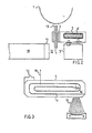
- the printer in particular of the dot type, comprises a cylinder 1, indicated simply by a dashed line, in front of which moves a carriage 2 carrying the print head 3 formed of several, for example 7, print hammers 4 arranged side by side.
- the carriage 2 runs on a rectilinear guide rail 5, parallel to the cylinder 1, on which is disposed a recording medium, such as a sheet of paper, which are struck by the hammers of the print head 3.
- the displacement of carriage 2 is achieved by of a linear motor, the armature of which is formed by a coil 6 wound on a support member 7, for example a duralumin bar, forming the body of the carriage which circulates in its guide rail 5, by means of a system suitable bearing 8, for example ball bearings.
- the guide rail 5 is constituted by a horizontal metal bar in which is located a rectilinear groove of square or rectangular section traversed by two of the rolling members on one side of the carriage, the two other rolling members running laterally. , with a slight offset in height, on the bar or in a second groove.
- the inductor system of the linear motor is constituted according to the invention by a magnetic circuit formed by a closed yoke 9, here in the form of a rectangular ring, of which a longitudinal branch is formed by the guide rail 5 and which encloses a magnet NS 10 provided with a pole piece 11 separated from the rail 5 by an air gap 12 and which is fixed, on its other side (N) to the other longitudinal branch of the cylinder head (see Figure 1).
- the printing head 3 carries printing hammers 4 which are constituted by plane plates parallel to each other in close proximity to one another and comprising a pointed part 13 which forms the 'point striking body proper.
- These printing hammers can be of a known type, for example according to French patent No 73 05754 and as shown diagrammatically in FIG. 3.
- Such a printing hammer 4 is essentially formed by one or more spirals 14 cut from a flat metal plate of elongated shape provided with a part protruding point 13 used for printing a point of the character to be represented, and connected to a connection member 15 formed of metal tongues forming return spring and integral with a foot used for feeding the hammer by a current d appropriate excitation, said hammer being able to pivot about a horizontal axis 16.
- 7 hammers are thus used in parallel with each other in close proximity to each other and arranged vertically on the print head (see figure 2), so as to be partially or entirely in the air gap 12 of the linear motor.
- the movement of the carriage is obtained by controlling the linear motor, which, as is known, consists in the present case of sending an appropriate excitation current in the armature winding 6, which is placed in the field of induction (arrows 17 in FIG. 1) of the magnetic circuit already described, the combined action of this excitation current circulating in the winding 6 and of the inducing field creating a driving force of the carriage, to the right or the left along its rail guide, the air gap 12 extending over most of the length of the rail corresponding to the desired print length on the the printer.
- This linear motor control is carried out by means of a conventional system of the symmetrical output amplifier type connected to a motor control system, which will be described later.
- the motor operates with a displacement speed of lm / s.
- the invention provides for using the permanent field of the linear motor as the magnetic field by placing the flat hammers perpendicular to this field, on the print head 3.
- the hammer control current d impression 4 can be produced for example by an amplifier with two transistors blocked or saturated simultaneously and producing the desired current as a function of the control signal.
- an ultrasonic radar transmitter / receiver system is used.
- an ultrasonic transmitter 19 placed on the print head and a fixed ultrasonic receiver 20 mounted on one side of the printer chassis, the transmitter being arranged by being aligned with the receiver and moving parallel to the guide rail 5, by being at the same height as the receiver 20 relative to the rail and at a variable distance x from said receiver.
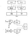
- FIG. 4 there is shown the block diagram of the location system according to the invention.
- the principle of localization or detection consists in comparing the phase of the ultrasonic signal (pure maintained wave) emitted with that of the signal received by the receiver, the latter and the transmitter being usual transducers.
- the phase difference is measured by counting the zero crossings of the phase difference, and the number of periods of the sustained wave between the transmitter and the receiver is measured, celebrating equal to the width of a character. (2.5 mm) due to the choice of a frequency of for example 137 kHz for the ultrasonic localization system.
- This has the effect that each zero crossing of the phase determines the start of a character, with as precision of the 1 / 64th character system.
- FIG. 5 shows a possible embodiment of such a location system.
- the phase-shift measurement device 21 is constituted by conventional shaping amplifiers 24 and by an AND gate 25, the output of which is connected to an appropriate counter 26.
- the position counting device 22 is formed for example of a usual amplifier 27 the output of which is connected to the clock input H of a counter 28.
- the outputs of the counters 26 and 28 are connected to a register 29 used for the 'display.
- the transition to zero of the phase difference between the transmitted wave V E and the received wave V R is detected by the device 21 for phase shift measurement (assembly 24, 25).
- the position counting system 22 detects each zero crossing of the transmitted signal, detected by the amplifier 27.
- the system 21 delivers its signal to the counter 26 which totals the number of elementary resolution points necessary for the definition of a character corresponding to, and transmits the least significant bits to register 29. Furthermore, the output of amplifier 27 is connected to the clock input of counter 28 (which can be a ring counter, which is reset to zero each time the carriage carrying the transmitter 19 returns to the starting position, to the left of the printer, against the receiver 20), this counter totals the number of periods traversed by the head d printing and sends it in the form of most significant bits to the register 29.
- the counter 28 performs its counting at n bits.
- phase difference it is possible to digitally measure the phase difference, and to code it on 6 bits, to count the zero crossings of the phase difference with, ultimately, a coding of the position on 14 bits and, for viewing , a display on 4 hexadecimal digits.
- the wavelength increases.
- the wavelength is 2.5 mm, which corresponds to the length of a printed character.
- the propagation speed is increased to 347 m / s due to the increase in temperature.
- the position at the end of the line is different from 2100.
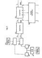
- This difference once measured and transformed into a voltage will directly correct the frequency by an oscillator controlled in frequency by the voltage V.
- the real position is put in memory (memory 30) at the moment when the end contact is triggered line, then subtract 2100 (complementation at 31 and adder 32).
- the difference enters into a counter 33, therefore the content is immediately transferred in + or in -, depending on the sign, by a transfer system 34 in a second counter 35 which accumulates this difference with that found previously, and this so as to preserve the constant wavelength despite successive modifications of the propagation medium.
- the content of the second counter 35 transformed by a digital analog converter 36 and divided at the output 37 in a potentiometric ratio is added to a fixed voltage, which corresponds to the uncorrected frequency and controls a VCO oscillator controlled in frequency by the voltage.
- the printer according to the invention also includes a system for controlling the speed of movement of the print head, which is required by typing at constant speed.
- the system designed is a digital speed control on a reference speed which is given by the control unit, depending on whether or not the print head is typing, whether it is moving in one direction or in the other or that it is stopped.
- the measurement made of the speed is in fact the measurement of the displacement carried out in regular time intervals. This time base is given by the transmitter of the location system.
- the period of the transmission signal being 7.3 us (137 kHz), it is necessary to reduce this frequency before using it for speed measurement.
- the time taken to traverse a resolution point is of the order of 40 us and a measurement carried out every 7 us would therefore be largely redundant.
- the transmitter frequency is therefore divided by 128, using two counters, which reduces it to a value slightly above 1 kHz.
- the position variation between two measurements is 27 resolution points (1 / 64th of a character), i.e. a variation of the last 5 bits of the word indicating the position, while at 0, 3 m / sec, there is a displacement of 10 points, coded on 3 bits of the position counter.
- FIG. 7 which represents the diagram of the speed control system of the print head, there is shown the position counter 38 connected to the position indicator at 14 bits, and the output of which is connected to a first flip-flop 39 connected to a second flip-flop 40.
- the inputs of these two flip-flops 39, 40 are connected by respective NAND gates 41 and 42 to a counter device 43 constituting a divider by 128 which delivers to said doors the transmission frequency of 137 kHz divided by 128.
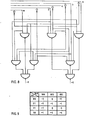
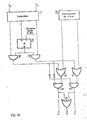
- the two flip-flops are connected to each other and respectively to a subtracting device 44, the output of which is connected to a comparator 45 leading itself to a combinatorial system 46, the detailed diagram of which is shown in FIG. 8 and which is connected to the operational amplifier of the conventional type of the motor servo module.
- a combinatorial system 46 taking into account the result of the comparison, the sign of the reference speed and the sign of the observed displacement, determines whether to accelerate positively or negatively. When these operations are finished, the position xp is sent to the flip-flop 40 and then becomes the previous position. This instant is determined by the output of the NAND gate 42, which decodes the phase 1111101 of the counters 43.
- FIG. 10 shows the block diagram of the speed and position control system of the carriage carrying the print head.
- the system allowing this control is the same as the previous speed control system, supplemented by a position control.
- the principle is as follows: the print head being supposed to be at a point M (abscissa x variable M ) and to move towards a point A of abscissa x A , at the speed V, we let the system act speed control already described, alone, as long as point A has not been exceeded.
- a positioning system describes below converges the head towards position A in the following manner.
- the system used for this purpose comprises a comparator 47, comparing x M to x A and delivering to its outputs signals corresponding to the states: x A -x M greater than zero; x A -x M and which are sent to a system of the usual type of logic gates 48 to 545 including a flip-flop of type JK 55 and also receiving the signals from the speed control system represented at 56.
- the outputs designated by +1 , -1 and 0 controlling the amplifier of the motor servo module not shown.
Landscapes
- Engineering & Computer Science (AREA)
- Radar, Positioning & Navigation (AREA)
- Remote Sensing (AREA)
- Physics & Mathematics (AREA)
- Acoustics & Sound (AREA)
- Computer Networks & Wireless Communication (AREA)
- General Physics & Mathematics (AREA)
- Character Spaces And Line Spaces In Printers (AREA)
- Impact Printers (AREA)
Applications Claiming Priority (2)
| Application Number | Priority Date | Filing Date | Title |
|---|---|---|---|
| FR7915626A FR2459137A1 (fr) | 1979-06-19 | 1979-06-19 | Imprimante a radar ultrasonique |
| FR7915626 | 1979-06-19 |
Publications (2)
| Publication Number | Publication Date |
|---|---|
| EP0021966A1 true EP0021966A1 (de) | 1981-01-07 |
| EP0021966B1 EP0021966B1 (de) | 1984-08-22 |
Family
ID=9226768
Family Applications (1)
| Application Number | Title | Priority Date | Filing Date |
|---|---|---|---|
| EP80400863A Expired EP0021966B1 (de) | 1979-06-19 | 1980-06-13 | Druckwerk mit einem Ultraschall-Radar |
Country Status (5)
| Country | Link |
|---|---|
| US (1) | US4349285A (de) |
| EP (1) | EP0021966B1 (de) |
| JP (1) | JPS565778A (de) |
| DE (1) | DE3069014D1 (de) |
| FR (1) | FR2459137A1 (de) |
Families Citing this family (3)
| Publication number | Priority date | Publication date | Assignee | Title |
|---|---|---|---|---|
| US4547089A (en) * | 1983-08-19 | 1985-10-15 | At&T Teletype Corporation | Guide for a print head of a printing device |
| US7971487B2 (en) | 2008-05-02 | 2011-07-05 | Carlen Controls, Inc. | Linear position transducer with wireless read head |
| US11708619B2 (en) * | 2019-02-21 | 2023-07-25 | Beijing Institute Of Technology | Method and device for reducing and homogenizing residual stress of a component |
Citations (1)
| Publication number | Priority date | Publication date | Assignee | Title |
|---|---|---|---|---|
| US3898555A (en) * | 1973-12-19 | 1975-08-05 | Tempo Instr Inc | Linear distance measuring device using a moveable magnet interacting with a sonic waveguide |
Family Cites Families (5)
| Publication number | Priority date | Publication date | Assignee | Title |
|---|---|---|---|---|
| US3950685A (en) * | 1974-04-25 | 1976-04-13 | Lrc, Inc. | Dc motor position controller |
| US4044881A (en) * | 1976-04-13 | 1977-08-30 | International Business Machines Corporation | Serial printer with linear motor drive |
| DE2654075A1 (de) * | 1976-11-29 | 1978-06-01 | Papst Motoren Kg | Linearmotor |
| US4146922A (en) * | 1977-08-29 | 1979-03-27 | Ncr Corporation | Constant velocity driving means |
| US4208142A (en) * | 1978-11-30 | 1980-06-17 | Burroughs Corporation | Print head locating utilizing sonic techniques |
-
1979
- 1979-06-19 FR FR7915626A patent/FR2459137A1/fr active Granted
-
1980
- 1980-06-13 DE DE8080400863T patent/DE3069014D1/de not_active Expired
- 1980-06-13 EP EP80400863A patent/EP0021966B1/de not_active Expired
- 1980-06-19 US US06/161,148 patent/US4349285A/en not_active Expired - Lifetime
- 1980-06-19 JP JP8220980A patent/JPS565778A/ja active Pending
Patent Citations (1)
| Publication number | Priority date | Publication date | Assignee | Title |
|---|---|---|---|---|
| US3898555A (en) * | 1973-12-19 | 1975-08-05 | Tempo Instr Inc | Linear distance measuring device using a moveable magnet interacting with a sonic waveguide |
Non-Patent Citations (1)
| Title |
|---|
| IBM TECHNICAL DISCLOSURE BULLETIN, Vol. 20, No. 1, Juin 1977, page 259 Armonk US R.R. LISK: "Electronic Keyboard" * En entier * * |
Also Published As
| Publication number | Publication date |
|---|---|
| JPS565778A (en) | 1981-01-21 |
| DE3069014D1 (en) | 1984-09-27 |
| US4349285A (en) | 1982-09-14 |
| EP0021966B1 (de) | 1984-08-22 |
| FR2459137A1 (fr) | 1981-01-09 |
| FR2459137B1 (de) | 1983-07-22 |
Similar Documents
| Publication | Publication Date | Title |
|---|---|---|
| EP3037898B1 (de) | Elektromechanisches gerät, das einen kapazitiven detektor der winkelposition eines mobilen elementes umfasst, und verfahren zur detektion der winkelposition eines mobilen elementes | |
| FR2538535A1 (fr) | Dispositif de detection de position a resolution elevee, notamment pour la tige d'accord d'un magnetron | |
| FR2513382A1 (fr) | Dispositif de commande d'un moteur lineaire et dispositif pour distinguer des impulsions valides d'impulsions parasites | |
| FR2495345A1 (fr) | Photocopieur a entrainement du systeme d'analyse | |
| FR2668258A1 (fr) | Capteur d'angle de rotation pour detecter le sens de rotation et/ou le nombre de tours effectues, et dispositif de direction assitee de vehicule comportant un tel capteur. | |
| FR2587402A1 (fr) | Appareil pour detecter des informations relatives au deplacement d'une porte dans un systeme de porte automatique | |
| CH636196A5 (fr) | Procede de codage et codeur angulaire pour la mise en oeuvre de ce procede. | |
| EP0952426B1 (de) | Uhrwerk mit einem induktiven oder kapazitiven Sensor zur Detektion von mindestens einem Drehwinkel eines Zahnrades innerhalb des Uhrwerkes | |
| EP0021966B1 (de) | Druckwerk mit einem Ultraschall-Radar | |
| FR2512247A1 (fr) | Systeme et procede de positionnement d'une structure de tetes d'enregistrement/reproduction | |
| FR2512742A1 (fr) | Dispositif d'impression a densite variable pour imprimante | |
| EP0021965B1 (de) | Druckwerk mit Linearmotor | |
| EP0609398B1 (de) | Verfahren und anordnung zum aufzeichnen-wiedergeben von information auf einem beweglichen optischen oder magneto-optischen aufzeichnungsträger | |
| FR2514173A1 (fr) | Procede de determination de positions de depart d'impression pour une imprimante par points du type a percussion | |
| EP0194911B1 (de) | Winkelpositionsmessvorrichtung mit Coderad | |
| CH463228A (fr) | Dispositif destiné à assurer une tension ou à fixer une position repérée prédéterminée de sections consécutives d'une bande en mouvement dans une machine effectuant des travaux sur ladite bande | |
| BE1001316A3 (fr) | Dispositif d'enregistrement de code de cle electronique. | |
| FR2534189A1 (fr) | Procede d'impression pour une imprimante par points | |
| EP0010021B1 (de) | Druckvorrichtung für Serien-Parallel-Drucker und mit dieser Druckvorrichtung ausgerüsteter Fernschreiber | |
| FR2464825A1 (fr) | Imprimante par points a percussion | |
| EP3259761A1 (de) | Messung durch atominterferometrie mit einer vielzahl von atomarten | |
| WO2023175046A1 (fr) | Dispositif de mesure du couple de torsion et de la poussée auxquels est soumis un arbre en rotation | |
| FR2665667A1 (fr) | Procede pour ajuster l'energie d'impression d'un caractere et machine a ecrire, imprimante ou analogue pour la mise en óoeuvre du procede. | |
| BE539080A (de) | ||
| EP0440621A1 (de) | Verfahren und vorrichtung zum steuern der mechanischen spannung eines laufenden fadens und zum messen seiner geschwindigkeit |
Legal Events
| Date | Code | Title | Description |
|---|---|---|---|
| PUAI | Public reference made under article 153(3) epc to a published international application that has entered the european phase |
Free format text: ORIGINAL CODE: 0009012 |
|
| AK | Designated contracting states |
Designated state(s): BE CH DE GB IT LI LU NL |
|
| 17P | Request for examination filed |
Effective date: 19810305 |
|
| ITF | It: translation for a ep patent filed |
Owner name: FUMERO BREVETTI S.N.C. |
|
| GRAA | (expected) grant |
Free format text: ORIGINAL CODE: 0009210 |
|
| AK | Designated contracting states |
Designated state(s): BE CH DE GB IT LI LU NL |
|
| REF | Corresponds to: |
Ref document number: 3069014 Country of ref document: DE Date of ref document: 19840927 |
|
| NLT1 | Nl: modifications of names registered in virtue of documents presented to the patent office pursuant to art. 16 a, paragraph 1 |
Owner name: BULL MICRAL TE ORSAY, FRANKRIJK. |
|
| PLBE | No opposition filed within time limit |
Free format text: ORIGINAL CODE: 0009261 |
|
| STAA | Information on the status of an ep patent application or granted ep patent |
Free format text: STATUS: NO OPPOSITION FILED WITHIN TIME LIMIT |
|
| 26N | No opposition filed | ||
| ITTA | It: last paid annual fee | ||
| EPTA | Lu: last paid annual fee | ||
| PGFP | Annual fee paid to national office [announced via postgrant information from national office to epo] |
Ref country code: BE Payment date: 19950510 Year of fee payment: 16 |
|
| PGFP | Annual fee paid to national office [announced via postgrant information from national office to epo] |
Ref country code: LU Payment date: 19950601 Year of fee payment: 16 |
|
| PGFP | Annual fee paid to national office [announced via postgrant information from national office to epo] |
Ref country code: GB Payment date: 19950608 Year of fee payment: 16 |
|
| PGFP | Annual fee paid to national office [announced via postgrant information from national office to epo] |
Ref country code: NL Payment date: 19950629 Year of fee payment: 16 |
|
| PGFP | Annual fee paid to national office [announced via postgrant information from national office to epo] |
Ref country code: DE Payment date: 19950809 Year of fee payment: 16 |
|
| PGFP | Annual fee paid to national office [announced via postgrant information from national office to epo] |
Ref country code: CH Payment date: 19950929 Year of fee payment: 16 |
|
| PG25 | Lapsed in a contracting state [announced via postgrant information from national office to epo] |
Ref country code: LU Free format text: LAPSE BECAUSE OF NON-PAYMENT OF DUE FEES Effective date: 19960613 Ref country code: GB Effective date: 19960613 |
|
| PG25 | Lapsed in a contracting state [announced via postgrant information from national office to epo] |
Ref country code: LI Effective date: 19960630 Ref country code: CH Effective date: 19960630 Ref country code: BE Effective date: 19960630 |
|
| BERE | Be: lapsed |
Owner name: REALISATIONS ETUDES ELECTRONIQUES Effective date: 19960630 |
|
| PG25 | Lapsed in a contracting state [announced via postgrant information from national office to epo] |
Ref country code: NL Effective date: 19970101 |
|
| GBPC | Gb: european patent ceased through non-payment of renewal fee |
Effective date: 19960613 |
|
| REG | Reference to a national code |
Ref country code: CH Ref legal event code: PL |
|
| PG25 | Lapsed in a contracting state [announced via postgrant information from national office to epo] |
Ref country code: DE Effective date: 19970301 |
|
| NLV4 | Nl: lapsed or anulled due to non-payment of the annual fee |
Effective date: 19970101 |