EP0021945B1 - Hydrophone à fibre optique monomode fonctionnant par effet élasto-optique - Google Patents
Hydrophone à fibre optique monomode fonctionnant par effet élasto-optique Download PDFInfo
- Publication number
- EP0021945B1 EP0021945B1 EP80400838A EP80400838A EP0021945B1 EP 0021945 B1 EP0021945 B1 EP 0021945B1 EP 80400838 A EP80400838 A EP 80400838A EP 80400838 A EP80400838 A EP 80400838A EP 0021945 B1 EP0021945 B1 EP 0021945B1
- Authority
- EP
- European Patent Office
- Prior art keywords
- optic
- hydrophone
- radiation
- fiber
- optical
- Prior art date
- Legal status (The legal status is an assumption and is not a legal conclusion. Google has not performed a legal analysis and makes no representation as to the accuracy of the status listed.)
- Expired
Links
- 230000000694 effects Effects 0.000 title claims description 8
- 239000000835 fiber Substances 0.000 claims description 42
- 230000005855 radiation Effects 0.000 claims description 22
- 230000010363 phase shift Effects 0.000 claims description 21
- 238000005259 measurement Methods 0.000 claims description 17
- 230000006798 recombination Effects 0.000 claims description 9
- 238000005215 recombination Methods 0.000 claims description 9
- 230000035945 sensitivity Effects 0.000 claims description 8
- 230000003993 interaction Effects 0.000 claims description 7
- 239000004065 semiconductor Substances 0.000 claims description 5
- 238000001514 detection method Methods 0.000 claims description 3
- 230000000295 complement effect Effects 0.000 claims description 2
- 230000008878 coupling Effects 0.000 claims description 2
- 238000010168 coupling process Methods 0.000 claims description 2
- 238000005859 coupling reaction Methods 0.000 claims description 2
- 238000000926 separation method Methods 0.000 claims description 2
- 238000001914 filtration Methods 0.000 claims 2
- 230000003287 optical effect Effects 0.000 description 33
- 239000013307 optical fiber Substances 0.000 description 20
- 239000000758 substrate Substances 0.000 description 7
- JBRZTFJDHDCESZ-UHFFFAOYSA-N AsGa Chemical compound [As]#[Ga] JBRZTFJDHDCESZ-UHFFFAOYSA-N 0.000 description 2
- 229910017214 AsGa Inorganic materials 0.000 description 2
- VYPSYNLAJGMNEJ-UHFFFAOYSA-N Silicium dioxide Chemical compound O=[Si]=O VYPSYNLAJGMNEJ-UHFFFAOYSA-N 0.000 description 2
- 238000005305 interferometry Methods 0.000 description 2
- 238000000034 method Methods 0.000 description 2
- 230000000644 propagated effect Effects 0.000 description 2
- 230000001902 propagating effect Effects 0.000 description 2
- XLYOFNOQVPJJNP-UHFFFAOYSA-N water Substances O XLYOFNOQVPJJNP-UHFFFAOYSA-N 0.000 description 2
- RTAQQCXQSZGOHL-UHFFFAOYSA-N Titanium Chemical compound [Ti] RTAQQCXQSZGOHL-UHFFFAOYSA-N 0.000 description 1
- 238000010586 diagram Methods 0.000 description 1
- 238000009792 diffusion process Methods 0.000 description 1
- CPBQJMYROZQQJC-UHFFFAOYSA-N helium neon Chemical compound [He].[Ne] CPBQJMYROZQQJC-UHFFFAOYSA-N 0.000 description 1
- 230000001939 inductive effect Effects 0.000 description 1
- 230000010354 integration Effects 0.000 description 1
- GQYHUHYESMUTHG-UHFFFAOYSA-N lithium niobate Chemical compound [Li+].[O-][Nb](=O)=O GQYHUHYESMUTHG-UHFFFAOYSA-N 0.000 description 1
- 239000000463 material Substances 0.000 description 1
- 230000005693 optoelectronics Effects 0.000 description 1
- 239000000377 silicon dioxide Substances 0.000 description 1
- 229910052719 titanium Inorganic materials 0.000 description 1
- 239000010936 titanium Substances 0.000 description 1
Images
Classifications
-
- G—PHYSICS
- G01—MEASURING; TESTING
- G01H—MEASUREMENT OF MECHANICAL VIBRATIONS OR ULTRASONIC, SONIC OR INFRASONIC WAVES
- G01H9/00—Measuring mechanical vibrations or ultrasonic, sonic or infrasonic waves by using radiation-sensitive means, e.g. optical means
- G01H9/004—Measuring mechanical vibrations or ultrasonic, sonic or infrasonic waves by using radiation-sensitive means, e.g. optical means using fibre optic sensors
-
- G—PHYSICS
- G02—OPTICS
- G02F—OPTICAL DEVICES OR ARRANGEMENTS FOR THE CONTROL OF LIGHT BY MODIFICATION OF THE OPTICAL PROPERTIES OF THE MEDIA OF THE ELEMENTS INVOLVED THEREIN; NON-LINEAR OPTICS; FREQUENCY-CHANGING OF LIGHT; OPTICAL LOGIC ELEMENTS; OPTICAL ANALOGUE/DIGITAL CONVERTERS
- G02F1/00—Devices or arrangements for the control of the intensity, colour, phase, polarisation or direction of light arriving from an independent light source, e.g. switching, gating or modulating; Non-linear optics
- G02F1/01—Devices or arrangements for the control of the intensity, colour, phase, polarisation or direction of light arriving from an independent light source, e.g. switching, gating or modulating; Non-linear optics for the control of the intensity, phase, polarisation or colour
- G02F1/0128—Devices or arrangements for the control of the intensity, colour, phase, polarisation or direction of light arriving from an independent light source, e.g. switching, gating or modulating; Non-linear optics for the control of the intensity, phase, polarisation or colour based on electro-mechanical, magneto-mechanical, elasto-optic effects
- G02F1/0131—Devices or arrangements for the control of the intensity, colour, phase, polarisation or direction of light arriving from an independent light source, e.g. switching, gating or modulating; Non-linear optics for the control of the intensity, phase, polarisation or colour based on electro-mechanical, magneto-mechanical, elasto-optic effects based on photo-elastic effects, e.g. mechanically induced birefringence
- G02F1/0134—Devices or arrangements for the control of the intensity, colour, phase, polarisation or direction of light arriving from an independent light source, e.g. switching, gating or modulating; Non-linear optics for the control of the intensity, phase, polarisation or colour based on electro-mechanical, magneto-mechanical, elasto-optic effects based on photo-elastic effects, e.g. mechanically induced birefringence in optical waveguides
Definitions
- the invention relates to the field of acoustic detection in a marine environment and more particularly relates to a hydrophone with a single mode optical fiber operating by elasto-optical effect, using the interaction effects between the acoustic wave to be detected and a single mode fiber on which this acoustic wave acts.
- a fiber optic hydrophone is known from the article by P. SHAJENKO et al., Published in “Journal of the Acoustical Society of America vol. 64, n ° 5, Nov. 1978, p.1286-1288.
- This hydrophone comprises a measurement optical fiber and a reference optical fiber, means making it possible to distribute the light coming from the source laser between the two fibers, and means making it possible to recombine the two optical waves thus distributed and to analyze the signal.
- these means consist of discrete elements such as lenses, semi-transparent blades, slits, all elements liable to move and in any event requiring their precise alignment for each measurement and ensuring that they are not subjected to untimely movements during measurement which would distort the results.
- the invention proposes a hydrophone comprising in particular a single-mode optical fiber immersed in water where the sound wave propagates.
- the propagation of pressure variations which elasto-optically cause variations in the geometric and optical parameters of the fiber.
- An optical wave propagating in the optical fiber undergoes phase variations capable of being detected by interferometry, by means of a second single-mode optical fiber forming reference arm.
- the optical connections between the optical fiber immersed in water, which forms the measuring arm, and the reference optical fiber are established in a rigid and compact optical structure and produced by the techniques of integrated optics so as to avoid any adjustment of the device in operation.
- means are provided for introducing a phase shift on one of its arms to maintain the phase shift between the two waves at a value where the sensitivity is maximum.
- the subject of the invention is therefore a single mode fiber optic hydrophone operating by elasto-optical effect, comprising a single mode laser source coupled to an integrated optical circuit board in which are made means for separating the radiation from the source to the first two. integrated optical guides and means for recombining the radiation guided by two second integrated optical guides, a first single-mode optical fiber forming a measurement arm intended to be immersed in an interaction medium subjected to the acoustic wave to be detected, and a second fiber single-mode optic forming reference arm, these two fibers having their ends rigidly coupled respectively to one of the first and to one of the second optical guides, the hydrophone further comprising an electrically controlled phase modulator acting on one integrated optical guides for introducing a phase shift between the guided waves, means for detecting radiation emerging from s recombination means, and a device for processing the detected signals intended to supply a control signal to the phase modulator such that the phase difference between the two arms independent of the acoustic wave to be detected is kept close to a point of maximum
- the hydrophone according to the invention has an interferometer structure and comprises, on one of the optical paths of the interferometer, a single-mode optical fiber immersed in the acoustic wave field to be detected assumed to be uniform, of pressure P and of frequency ⁇ s .
- This acoustic wave field induces by elasto-optical effect a variation of index ⁇ n of the index n of the fiber.
- This variation in index results in a phase shift ⁇ as a function of the variation in index An, the length I of the submerged fiber and the wavelength X of the optical wave:
- index ⁇ n is equal to ⁇ n o sin ⁇ st
- ⁇ n o 1/2 n 3 ⁇ P e ⁇ P / E
- P e being the photoelastic constant of the fiber
- E being the YOUNG modulus of the forming material the fiber
- P / E is the stress applied to the fiber by the acoustic wave field
- the propagation time of the optical wave in this fiber is 3 ⁇ s.
- the pressures measurable by the fiber optic hydrophone depend on the incident optical power, the attenuation in the fiber at the wavelength used, the sensitivity of the photodetector receiving the radiation resulting from interference between the optical wave which s 'is propagated in the measuring arm and the optical wave which has propagated in the reference arm, and the length of the fiber subjected to the pressure field; a compromise must be made between an increase in the length of the fiber and the optical power available on the photodetector taking into account the attenuation introduced by a very long length of fiber.
- the optical paths in the measurement arm comprising the optical fiber subjected to the sound pressure field, and in the reference arm are equivalent.
- an optical fiber with the same characteristics as the optical fiber of the measurement arm Given the long lengths of fiber to be used and for a reduced bulk, these fibers can be wound.
- optical paths in the interferometer are fixed and do not vary when the device is working, and, so that the conditions of propagation of the optical wave are sufficient stable, it is particularly advantageous to make the optical connections between the source, the ends of the optical fibers and the detector rigidly, the technique of integrated optics being particularly suitable for enabling the correct operation of such a device.
- such a structure makes it possible to introduce active microstructures electrically controlled on the optical paths to significantly improve the operation of the device.
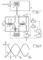
- Figure 1 shows an embodiment of the hydrophone according to the invention. It comprises an electro-optical substrate 1, for example made of lithium niobate in which optical waveguides are produced by diffusion of titanium, to make the optical connections.
- the light source is a semiconductor laser 2, AsGa for example, coupled by the wafer to a micro-guide 3 produced in the substrate which receives the radiation emitted by the source.
- a directional coupler 4 makes it possible to transfer a portion of the light guided in the guide 3 to a guide 5, these guides 3 and 5 directing the radiation respectively to the measurement arm and to the reference arm.
- a wound single-mode optical fiber 6 has one end coupled to the edge of the substrate to receive the radiation guided in the guide 3 and its other end coupled to the edge of the substrate to transmit the emerging radiation to a receiving guide 7.
- a wound single-mode optical fiber 8 has one end coupled to the edge of the substrate to receive the radiation guided in the guide 5 and its other end coupled to the edge of the substrate to transmit the emerging radiation to a receiving guide 9 .
- the optical fiber 6 which is in the measurement arm is immersed in the acousto-optical interaction medium 12.
- An electroacoustic transducer 13 emitting the sound wave to be detected has been shown in the interaction medium.
- the acoustic wave creates pressure variations in the medium causing variations in the geometric parameters of the fiber, these variations inducing variations in index in this fiber by electro-optical effect.
- This effect is small, but due to the long fiber length in which the guided wave propagates, the phase variation due to the acoustic wave is measurable.
- This measurement is carried out by interferometry, the reference wave propagating in the single-mode optical fiber 8.
- This reference fiber is placed outside the acoustic field and the optical wave which it transmits therefore does not undergo variations in its conditions propagation due to the acoustic wave.
- the maximum sensitivity of such an interferometer is obtained when the relative phase shift between the two arms is equal to ⁇ / 2.
- This condition could be obtained by creating between the two arms a fixed phase shift equal to T r / 2, the variable phase shift at the frequency of the acoustic wave, due to the acoustic wave acting on the optical fiber, being superimposed on this phase shift. fixed so that small variations in ⁇ are detected within a maximum sensitivity range.
- the device according to the invention makes it possible to overcome phase variations between the two arms of the interferometer by adding to the variable phase shift due to the variations in the propagation conditions ⁇ al ⁇ another variable phase shift ⁇ el created by means of a modulator. phase with electrical control placed on one of the waveguides of the integrated optical circuit such that the sum ⁇ al + ⁇ el is substantially equal to T r / 2, the small variations in phase shift due to the acoustic wave at the frequency ⁇ s which are superimposed on this almost fixed phase shift, being detected in a range where the sensitivity is maximum.
- reception guides 7 and 9 rece the radiation emerging respectively from the fiber forming the measuring arm 6 and the fiber forming the reference arm 8 are coupled over a predefined interaction length to form a directional coupler 10.
- the coupling rate is adjustable by electrical control, two electrodes being provided for this purpose along the two guides.
- cp (t) is the phase difference between the two arms of the interferometer which is not due to the acoustic wave
- l intensity detected by one of the photodetectors is: and that detected on the other channel is: 1 0 being the intensity of the optical radiation flowing in the measurement fiber and in the reference fiber.
- Low-pass filters 15 and 16 receiving the output signals from detectors 11 and 14 respectively, deliver variable signals, with variations in propagation conditions, according to d (t), that is to say and
- the measurement signal can then be obtained from the output signal from one of the photodetectors, for example the photodetector 11 whose output signal varies as: by means of a processing circuit 19 providing a signal S proportional to the phase shift between the two optical waves due to the acoustic wave.
- the invention is not limited to the embodiment of the hydrophone precisely described and produced.
- the source is a semiconductor laser source and the photodetectors of the photodiodes also with semiconductor, it is possible to integrate these two components on the electro-optical substrate itself.
- a gas laser source for example a helium-neon laser
- the function of separating the optical wave from the source between the measurement arm and the reference arm and the recombination function of the two optical waves emerging from these same arms were performed by means of two 3-way couplers. dB electrically controlled. Other active or passive means can ensure this separation and this recombination.
Landscapes
- Physics & Mathematics (AREA)
- General Physics & Mathematics (AREA)
- Nonlinear Science (AREA)
- Optics & Photonics (AREA)
- Measurement Of Mechanical Vibrations Or Ultrasonic Waves (AREA)
- Instruments For Measurement Of Length By Optical Means (AREA)
Applications Claiming Priority (2)
| Application Number | Priority Date | Filing Date | Title |
|---|---|---|---|
| FR7916899A FR2460582A1 (fr) | 1979-06-29 | 1979-06-29 | Hydrophone a fibre optique monomode fonctionnant par effet elasto-optique |
| FR7916899 | 1979-06-29 |
Publications (2)
| Publication Number | Publication Date |
|---|---|
| EP0021945A1 EP0021945A1 (fr) | 1981-01-07 |
| EP0021945B1 true EP0021945B1 (fr) | 1982-11-03 |
Family
ID=9227308
Family Applications (1)
| Application Number | Title | Priority Date | Filing Date |
|---|---|---|---|
| EP80400838A Expired EP0021945B1 (fr) | 1979-06-29 | 1980-06-10 | Hydrophone à fibre optique monomode fonctionnant par effet élasto-optique |
Country Status (5)
| Country | Link |
|---|---|
| US (1) | US4320475A (enExample) |
| EP (1) | EP0021945B1 (enExample) |
| JP (1) | JPS5612518A (enExample) |
| DE (1) | DE3061030D1 (enExample) |
| FR (1) | FR2460582A1 (enExample) |
Families Citing this family (51)
| Publication number | Priority date | Publication date | Assignee | Title |
|---|---|---|---|---|
| US4363114A (en) * | 1981-01-21 | 1982-12-07 | The United States Of America As Represented By The Secretary Of The Navy | Low noise remote optical fiber sound detector |
| US4436365A (en) | 1981-10-21 | 1984-03-13 | Bell Telephone Laboratories, Incorporated | Data link using integrated optics devices |
| DE3148158A1 (de) * | 1981-12-05 | 1983-06-09 | Honeywell-Elac-Nautik Gmbh, 2300 Kiel | Wasserschallempfaenger mit lichtleitfaser |
| FR2520112B1 (fr) * | 1982-01-15 | 1985-12-06 | Chevron Res | Dispositif et procede de detection de signaux acoustiques par des fibres optiques |
| FR2520110B1 (fr) * | 1982-01-15 | 1988-03-25 | Chevron Res | Procede et dispositif pour amplifier le decalage spectral des pics de transmission d'un interferometre |
| US4418981A (en) * | 1982-01-19 | 1983-12-06 | Gould Inc. | Quadrature fiber-optic interferometer matrix |
| US4977546A (en) * | 1982-01-29 | 1990-12-11 | The United States Of America As Represented By The Secretary Of The Navy | Signal stabilization in optical hydrophones |
| US4436425A (en) | 1982-03-29 | 1984-03-13 | The United States Of America As Represented By The Secretary Of The Navy | Signal waveform detector using synthetic FM demodulation |
| JPS59500584A (ja) * | 1982-04-14 | 1984-04-05 | ザ・ボ−ド・オブ・トラスティ−ズ・オブ・ザ・レランド・スタンフォ−ド・ジュニア・ユニバ−シティ | ファイバ光学干渉計を用いたセンサ |
| US4486657A (en) * | 1982-05-27 | 1984-12-04 | The United States Of America As Represented By The Secretary Of The Navy | Phase-lock fiber optic interferometer |
| DE3231492A1 (de) * | 1982-08-25 | 1984-03-01 | ANT Nachrichtentechnik GmbH, 7150 Backnang | Integrierte mikro-optische vorrichtung |
| USH96H (en) | 1982-09-13 | 1986-08-05 | United States Of America | Intensity modulated light source |
| US4744625A (en) * | 1982-09-30 | 1988-05-17 | Gte Laboratories Incorporated | Methods of and apparatus for providing frequency modulated light |
| FR2541767B1 (fr) * | 1983-02-25 | 1986-11-21 | Thomson Csf | Hydrophone a fibre optique |
| US4547869A (en) * | 1983-04-04 | 1985-10-15 | Western Geophysical Company Of America | Marine seismic sensor |
| GB2147758B (en) * | 1983-08-24 | 1987-08-05 | Plessey Co Plc | Optical detecting and/or measuring |
| US4545253A (en) * | 1983-08-29 | 1985-10-08 | Exxon Production Research Co. | Fiber optical modulator and data multiplexer |
| JPH0694234B2 (ja) * | 1984-01-17 | 1994-11-24 | 富士写真フイルム株式会社 | 感光性平版印刷版 |
| US4897541A (en) * | 1984-05-18 | 1990-01-30 | Luxtron Corporation | Sensors for detecting electromagnetic parameters utilizing resonating elements |
| US4678905A (en) * | 1984-05-18 | 1987-07-07 | Luxtron Corporation | Optical sensors for detecting physical parameters utilizing vibrating piezoelectric elements |
| JPH0664154B2 (ja) * | 1984-10-11 | 1994-08-22 | ウエスターン アトラス インターナショナル インコーポレーテッド | 海底地震センサ |
| US4589285A (en) * | 1984-11-05 | 1986-05-20 | Western Geophysical Co. Of America | Wavelength-division-multiplexed receiver array for vertical seismic profiling |
| US4648082A (en) * | 1985-03-04 | 1987-03-03 | Western Geophysical Company Of America | Marine acoustic gradient sensor |
| US5051965A (en) * | 1985-04-19 | 1991-09-24 | Western Atlas International, Inc. | Acousto-optical marine sensor array |
| US4743113A (en) * | 1985-08-29 | 1988-05-10 | Western Atlas International, Inc. | Optical fiber interferometer network |
| US4726650A (en) * | 1985-09-27 | 1988-02-23 | Western Atlas International, Inc. | Optical accelerometer |
| US4649529A (en) * | 1985-12-02 | 1987-03-10 | Exxon Production Research Co. | Multi-channel fiber optic sensor system |
| JPH062434B2 (ja) * | 1986-11-20 | 1994-01-12 | 富士写真フイルム株式会社 | 平版印刷版用支持体 |
| JPH0267989A (ja) * | 1988-09-01 | 1990-03-07 | A T R Koudenpa Tsushin Kenkyusho:Kk | 重力波測定装置 |
| US5253309A (en) * | 1989-06-23 | 1993-10-12 | Harmonic Lightwaves, Inc. | Optical distribution of analog and digital signals using optical modulators with complementary outputs |
| GB9026587D0 (en) * | 1990-12-06 | 1991-04-24 | Marconi Gec Ltd | Improvements relating to optical fibre coil assemblies |
| JP2767727B2 (ja) * | 1991-11-05 | 1998-06-18 | 富士写真フイルム株式会社 | 平版印刷版用支持体の封孔処理方法及び装置 |
| US5247490A (en) * | 1992-06-04 | 1993-09-21 | Martin Marietta Corporation | Pressure-compensated optical acoustic sensor |
| FR2693069B1 (fr) * | 1992-06-26 | 1997-04-25 | Thomson Csf | Hydrophone a fibre optique et antenne comprenant de tels hydrophones. |
| WO1995033258A1 (de) * | 1994-05-30 | 1995-12-07 | Sonident Anstalt Liechtensteinischen Rechts | Verfahren und vorrichtung zur herstellung von kugelwellen im ultraschallbereich |
| RU2112229C1 (ru) * | 1996-01-29 | 1998-05-27 | Государственное предприятие "Всероссийский научно-исследовательский институт физико-технических и радиотехнических измерений" | Волоконно-оптический гидрофон |
| FR2755516B1 (fr) | 1996-11-05 | 1999-01-22 | Thomson Csf | Dispositif compact d'illumination |
| US6002646A (en) * | 1997-06-27 | 1999-12-14 | The United States Of America As Represented By The Secretary Of The Navy | Portable optical range tracking array |
| FR2784185B1 (fr) | 1998-10-06 | 2001-02-02 | Thomson Csf | Dispositif pour l'harmonisation entre une voie d'emission laser et une voie passive d'observation |
| US6256588B1 (en) * | 1999-06-11 | 2001-07-03 | Geosensor Corporation | Seismic sensor array with electrical to optical transformers |
| FR2819061B1 (fr) * | 2000-12-28 | 2003-04-11 | Thomson Csf | Dispositif de controle de polarisation dans une liaison optique |
| DE102008012982A1 (de) * | 2008-03-06 | 2009-09-17 | Gsi Helmholtzzentrum Für Schwerionenforschung Gmbh | Dispersionsmessung von optischen Fasern im laufenden Betrieb |
| FR2929000B1 (fr) * | 2008-03-18 | 2010-04-09 | Thales Sa | Capteur a fibre optique auto-reference et reseau de capteurs associe |
| FR2934365B1 (fr) * | 2008-07-25 | 2010-08-13 | Thales Sa | Capteur a fibre optique auto-reference a diffusion brillouin stimulee |
| US9770862B2 (en) | 2008-09-10 | 2017-09-26 | Kyton, Llc | Method of making adhesion between an optical waveguide structure and thermoplastic polymers |
| US9138948B2 (en) * | 2008-09-10 | 2015-09-22 | Kyton, Llc | Suspended and compact fiber optic sensors |
| FR3031590B1 (fr) * | 2015-01-09 | 2017-01-13 | Thales Sa | Capteur a fibre optique |
| FR3034190B1 (fr) * | 2015-03-23 | 2019-10-25 | Thales | Capteur a fibre optique distribue d'etat de contrainte |
| RU2625000C1 (ru) * | 2016-03-21 | 2017-07-11 | Федеральное государственное бюджетное учреждение науки Тихоокеанский океанологический институт им. В.И. Ильичева Дальневосточного отделения Российской академии наук (ТОИ ДВО РАН) | Лазерно-интерференционный измеритель градиента давления в жидкости |
| RU2627966C1 (ru) * | 2016-11-07 | 2017-08-14 | федеральное государственное бюджетное образовательное учреждение высшего образования "Московский государственный технический университет имени Н.Э. Баумана (национальный исследовательский университет)" (МГТУ им. Н.Э. Баумана) | Сверхчувствительная гидроакустическая антенна на основе волоконно-оптических гидрофонов, использующая многоэлементные приёмники |
| CN111504176B (zh) * | 2020-04-30 | 2021-03-30 | 浙江大学 | 一种基于两级执行器结构的大光程闭环测量系统 |
Family Cites Families (1)
| Publication number | Priority date | Publication date | Assignee | Title |
|---|---|---|---|---|
| US4193130A (en) * | 1978-09-07 | 1980-03-11 | The United States Of America As Represented By The Secretary Of The Navy | Fiber optic hydrophone for use as an underwater electroacoustic standard |
-
1979
- 1979-06-29 FR FR7916899A patent/FR2460582A1/fr active Granted
-
1980
- 1980-06-10 DE DE8080400838T patent/DE3061030D1/de not_active Expired
- 1980-06-10 EP EP80400838A patent/EP0021945B1/fr not_active Expired
- 1980-06-26 US US06/163,190 patent/US4320475A/en not_active Expired - Lifetime
- 1980-06-27 JP JP8674780A patent/JPS5612518A/ja active Granted
Also Published As
| Publication number | Publication date |
|---|---|
| DE3061030D1 (en) | 1982-12-09 |
| JPS5612518A (en) | 1981-02-06 |
| JPS6345047B2 (enExample) | 1988-09-07 |
| US4320475A (en) | 1982-03-16 |
| FR2460582B1 (enExample) | 1982-06-04 |
| EP0021945A1 (fr) | 1981-01-07 |
| FR2460582A1 (fr) | 1981-01-23 |
Similar Documents
| Publication | Publication Date | Title |
|---|---|---|
| EP0021945B1 (fr) | Hydrophone à fibre optique monomode fonctionnant par effet élasto-optique | |
| FR2542868A1 (fr) | Capteur a cavites de fabry-perot | |
| EP0326476B1 (fr) | Hydrophone à fibre optique et antenne associant une série d'hydrophones | |
| EP0120737B1 (fr) | Hydrophone à fibre optique | |
| EP0713077A1 (fr) | Procédé de détection et/ou de mesure de grandeur physiques utilisant un capteur distribué | |
| FR2590752A1 (fr) | Systeme de collecte de donnees a fibres optiques | |
| EP0023180A1 (fr) | Dispositif interférométrique de mesure de courant électrique à fibre optique | |
| FR2580072A1 (enExample) | ||
| FR2699295A1 (fr) | Dispositif de traitement optique de signaux électriques. | |
| EP0029777A1 (fr) | Atténuateur optique à atténuation contrôlée | |
| EP2635883A1 (fr) | Systeme interferometrique apolarise et procede de mesure interferometrique apolarise | |
| FR2515811A1 (fr) | Dispositif interferometrique de mesure de champ magnetique et capteur de courant electrique comportant un tel dispositif | |
| EP0018873B1 (fr) | Dispositif compact de couplage optique et gyromètre interferométrique à fibre optique comportant un tel dispositif | |
| EP3598068A1 (fr) | Dispositif à résonateur optique annulaire | |
| EP0141739A2 (fr) | Dispositif interférométrique de mesure d'une vitesse de rotation angulaire | |
| FR2728678A1 (fr) | Capteur du type modulation optique et appareil d'instrumentation de processus utilisant celui-ci | |
| EP0211804B1 (fr) | Système de détection à fibre optique incorporant un capteur à modulation d'intensité | |
| FR2508754A1 (fr) | Hydrophone a fibre optique avec capteur immerge passif | |
| WO2008110721A2 (fr) | Systeme de metrologie optique | |
| EP0290297B1 (fr) | Filtre de réjection de signaux optiques et applications aux interféromètres en anneaux | |
| EP1674878A1 (fr) | Sonde électro-optique de mesure de champs électriques ou électromagnétiques à asservissement de la longueur d'onde du point de fonctionnement | |
| EP4630763A1 (fr) | Dispositif de mesure d'une grandeur physique | |
| EP0526286A1 (fr) | Procédé de transmission par fibre optique d'un signal issu d'un capteur notamment d'un hydrophone | |
| EP4630762A1 (fr) | Dispositif de mesure d'une grandeur physique utilisant l'effet vernier optique | |
| FR2703541A1 (fr) | Dispositif d'interrogation et d'analyse d'un réseau de capteurs interférométriques de mesure en lumière polarisée. |
Legal Events
| Date | Code | Title | Description |
|---|---|---|---|
| PUAI | Public reference made under article 153(3) epc to a published international application that has entered the european phase |
Free format text: ORIGINAL CODE: 0009012 |
|
| AK | Designated contracting states |
Designated state(s): DE GB NL |
|
| 17P | Request for examination filed |
Effective date: 19810123 |
|
| GRAA | (expected) grant |
Free format text: ORIGINAL CODE: 0009210 |
|
| AK | Designated contracting states |
Designated state(s): DE GB NL |
|
| REF | Corresponds to: |
Ref document number: 3061030 Country of ref document: DE Date of ref document: 19821209 |
|
| PGFP | Annual fee paid to national office [announced via postgrant information from national office to epo] |
Ref country code: NL Payment date: 19850630 Year of fee payment: 6 |
|
| PG25 | Lapsed in a contracting state [announced via postgrant information from national office to epo] |
Ref country code: NL Effective date: 19870101 |
|
| NLV4 | Nl: lapsed or anulled due to non-payment of the annual fee | ||
| PGFP | Annual fee paid to national office [announced via postgrant information from national office to epo] |
Ref country code: GB Payment date: 19910524 Year of fee payment: 12 |
|
| PGFP | Annual fee paid to national office [announced via postgrant information from national office to epo] |
Ref country code: DE Payment date: 19910531 Year of fee payment: 12 |
|
| PG25 | Lapsed in a contracting state [announced via postgrant information from national office to epo] |
Ref country code: GB Effective date: 19920610 |
|
| GBPC | Gb: european patent ceased through non-payment of renewal fee |
Effective date: 19920610 |
|
| PG25 | Lapsed in a contracting state [announced via postgrant information from national office to epo] |
Ref country code: DE Effective date: 19930302 |
|
| PLBE | No opposition filed within time limit |
Free format text: ORIGINAL CODE: 0009261 |
|
| STAA | Information on the status of an ep patent application or granted ep patent |
Free format text: STATUS: NO OPPOSITION FILED WITHIN TIME LIMIT |