EP0021821A1 - Apparatus and method for trimming strip material - Google Patents
Apparatus and method for trimming strip material Download PDFInfo
- Publication number
- EP0021821A1 EP0021821A1 EP80302115A EP80302115A EP0021821A1 EP 0021821 A1 EP0021821 A1 EP 0021821A1 EP 80302115 A EP80302115 A EP 80302115A EP 80302115 A EP80302115 A EP 80302115A EP 0021821 A1 EP0021821 A1 EP 0021821A1
- Authority
- EP
- European Patent Office
- Prior art keywords
- strip
- knives
- trimmer
- heads
- carriage
- Prior art date
- Legal status (The legal status is an assumption and is not a legal conclusion. Google has not performed a legal analysis and makes no representation as to the accuracy of the status listed.)
- Ceased
Links
Images

Classifications
-
- B—PERFORMING OPERATIONS; TRANSPORTING
- B23—MACHINE TOOLS; METAL-WORKING NOT OTHERWISE PROVIDED FOR
- B23D—PLANING; SLOTTING; SHEARING; BROACHING; SAWING; FILING; SCRAPING; LIKE OPERATIONS FOR WORKING METAL BY REMOVING MATERIAL, NOT OTHERWISE PROVIDED FOR
- B23D19/00—Shearing machines or shearing devices cutting by rotary discs
- B23D19/04—Shearing machines or shearing devices cutting by rotary discs having rotary shearing discs arranged in co-operating pairs
- B23D19/06—Shearing machines or shearing devices cutting by rotary discs having rotary shearing discs arranged in co-operating pairs with several spaced pairs of shearing discs working simultaneously, e.g. for trimming or making strips
-
- Y—GENERAL TAGGING OF NEW TECHNOLOGICAL DEVELOPMENTS; GENERAL TAGGING OF CROSS-SECTIONAL TECHNOLOGIES SPANNING OVER SEVERAL SECTIONS OF THE IPC; TECHNICAL SUBJECTS COVERED BY FORMER USPC CROSS-REFERENCE ART COLLECTIONS [XRACs] AND DIGESTS
- Y10—TECHNICAL SUBJECTS COVERED BY FORMER USPC
- Y10T—TECHNICAL SUBJECTS COVERED BY FORMER US CLASSIFICATION
- Y10T83/00—Cutting
- Y10T83/525—Operation controlled by detector means responsive to work
- Y10T83/531—With plural work-sensing means
-
- Y—GENERAL TAGGING OF NEW TECHNOLOGICAL DEVELOPMENTS; GENERAL TAGGING OF CROSS-SECTIONAL TECHNOLOGIES SPANNING OVER SEVERAL SECTIONS OF THE IPC; TECHNICAL SUBJECTS COVERED BY FORMER USPC CROSS-REFERENCE ART COLLECTIONS [XRACs] AND DIGESTS
- Y10—TECHNICAL SUBJECTS COVERED BY FORMER USPC
- Y10T—TECHNICAL SUBJECTS COVERED BY FORMER US CLASSIFICATION
- Y10T83/00—Cutting
- Y10T83/525—Operation controlled by detector means responsive to work
- Y10T83/533—With photo-electric work-sensing means
-
- Y—GENERAL TAGGING OF NEW TECHNOLOGICAL DEVELOPMENTS; GENERAL TAGGING OF CROSS-SECTIONAL TECHNOLOGIES SPANNING OVER SEVERAL SECTIONS OF THE IPC; TECHNICAL SUBJECTS COVERED BY FORMER USPC CROSS-REFERENCE ART COLLECTIONS [XRACs] AND DIGESTS
- Y10—TECHNICAL SUBJECTS COVERED BY FORMER USPC
- Y10T—TECHNICAL SUBJECTS COVERED BY FORMER US CLASSIFICATION
- Y10T83/00—Cutting
- Y10T83/525—Operation controlled by detector means responsive to work
- Y10T83/538—Positioning of tool controlled
-
- Y—GENERAL TAGGING OF NEW TECHNOLOGICAL DEVELOPMENTS; GENERAL TAGGING OF CROSS-SECTIONAL TECHNOLOGIES SPANNING OVER SEVERAL SECTIONS OF THE IPC; TECHNICAL SUBJECTS COVERED BY FORMER USPC CROSS-REFERENCE ART COLLECTIONS [XRACs] AND DIGESTS
- Y10—TECHNICAL SUBJECTS COVERED BY FORMER USPC
- Y10T—TECHNICAL SUBJECTS COVERED BY FORMER US CLASSIFICATION
- Y10T83/00—Cutting
- Y10T83/647—With means to convey work relative to tool station
- Y10T83/6584—Cut made parallel to direction of and during work movement
- Y10T83/6587—Including plural, laterally spaced tools
- Y10T83/6588—Tools mounted on common tool support
-
- Y—GENERAL TAGGING OF NEW TECHNOLOGICAL DEVELOPMENTS; GENERAL TAGGING OF CROSS-SECTIONAL TECHNOLOGIES SPANNING OVER SEVERAL SECTIONS OF THE IPC; TECHNICAL SUBJECTS COVERED BY FORMER USPC CROSS-REFERENCE ART COLLECTIONS [XRACs] AND DIGESTS
- Y10—TECHNICAL SUBJECTS COVERED BY FORMER USPC
- Y10T—TECHNICAL SUBJECTS COVERED BY FORMER US CLASSIFICATION
- Y10T83/00—Cutting
- Y10T83/647—With means to convey work relative to tool station
- Y10T83/6584—Cut made parallel to direction of and during work movement
- Y10T83/6592—Interrelated work-conveying and tool-moving means
- Y10T83/6595—With means to move tool laterally of feed direction during cutting
-
- Y—GENERAL TAGGING OF NEW TECHNOLOGICAL DEVELOPMENTS; GENERAL TAGGING OF CROSS-SECTIONAL TECHNOLOGIES SPANNING OVER SEVERAL SECTIONS OF THE IPC; TECHNICAL SUBJECTS COVERED BY FORMER USPC CROSS-REFERENCE ART COLLECTIONS [XRACs] AND DIGESTS
- Y10—TECHNICAL SUBJECTS COVERED BY FORMER USPC
- Y10T—TECHNICAL SUBJECTS COVERED BY FORMER US CLASSIFICATION
- Y10T83/00—Cutting
- Y10T83/768—Rotatable disc tool pair or tool and carrier
- Y10T83/7684—With means to support work relative to tool[s]
- Y10T83/7693—Tool moved relative to work-support during cutting
- Y10T83/7697—Tool angularly adjustable relative to work-support
-
- Y—GENERAL TAGGING OF NEW TECHNOLOGICAL DEVELOPMENTS; GENERAL TAGGING OF CROSS-SECTIONAL TECHNOLOGIES SPANNING OVER SEVERAL SECTIONS OF THE IPC; TECHNICAL SUBJECTS COVERED BY FORMER USPC CROSS-REFERENCE ART COLLECTIONS [XRACs] AND DIGESTS
- Y10—TECHNICAL SUBJECTS COVERED BY FORMER USPC
- Y10T—TECHNICAL SUBJECTS COVERED BY FORMER US CLASSIFICATION
- Y10T83/00—Cutting
- Y10T83/768—Rotatable disc tool pair or tool and carrier
- Y10T83/7738—Optional tool pairs alternatively operative
Abstract
Edge trimming apparatus for trimming off wavy edges(1) of strip material (3), e.g. metal strip, wherein rotary trimming knives (9,11) for each edge (1) of the strip (3) are movable transversely relative to the advancing strip (3). The knives (9,11) are pivotally supported about vertical axis (29) and can have their transverse spacing adjusted, the support blocks (31) preferably being transversely slidable in guides (33) which are mounted on a carriage (35) which itself is transversely movable relative to the advancing strip (3). Edge sensors are located adjacent edge regions of the strip (3) and signals from the sensors are passed to a device, for example a hydraulic jack (45), for moving the carriage (35) transversely.
Preferably the support blocks (31) are adjustable by means of an electric motor (39) and a screw threaded shaft (37) connected to the motor (39) and passing through the blocks (31). The trimmer knives (9,11) may be supported on trimmer heads (13) pivotally connected by links (27) to the support blocks (31) and themselves adjustably spaced apart by means of a threaded tie rod passing through sleeves pivotally connected to the heads (13).
In a preferred arrangement the transverse adjustment mechanism is located beneath the trimmer heads (13) and if desired the trimmer heads (13) may be rotatable and carry spare sets of knives.
Description
- This invention relates to an apparatus for and method of trimming the Pdnes of continuous strip material, e.g. metal strip,and/orfor slitting the strip material into two or more narrower strips of material.
- Rolled metal strip, after its manufacture, will always have non-uniform or wavy edges which have to be trimmed before the strip is rolled into coils. Conventional edge trimmers utilise rotating circular knives to trim the edges of the strip in order to obtain an accurate and constant strip width. The trimmer knives may either be driven or free running. Normally, the knives, one arranged above the strip and the other below the strip, are set with predetermined horizontal and vertical clearances and they may be set parallel to the direction of advance of the strip past the knives or they may be set at a slight angle in order to achieve the optimum cutting action which is free from burrs. However, once the knives have been correctly set to trim a given thickness and width of strip, they are maintained in that position.
- Apart from having wavy edges, the whole strip may be badly shaped, i.e. it may not be straight and may be curved. Such faults often give rise to tracking problems and as the strip moves over a series of rolls in the processing or trimming line it can wander from side to side. It has been proposed therefore, to guide the strip accurately to the trimmer knives, otherwise sideways movement of the strip will cause one edge of the strip to run out of contact with the knives. This can cause disastrous results because invariably the knives will not re-engage the edge of the strip again. In order to guide the strip for known trimmer knives, several steering and guiding rolls have always been provided which are expensive-both because they constitute extra equipment and take up valuable space, and it is an object of this invention to overcome these disadvantages.
- In an alternative prior art proposal, instead of guiding the strip to the knives, the knives are moved axially relative to the line of advance of the strip (see, for example, U.K.Patent Specification No:1,335,477). This is not satisfactory with metal strips because the lateral forces bearing on the edges of the knives would be very large and the cutting edge of the knives would be damaged and possibly the knives themselves would break. In any event, it would certainly cause rapid wear which would call for replacement of the knives at frequent intervals.
- The present invention has been evolved to overcome the above problems in a relatively cheap and convenient manner.
- According to the present invention, we provide a method of trimming the edges of and/or slitting strip material wherein the strip is advanced past at least one knife and the said at least one knife is pivotally supported, for steering ! movement transversely of the strip, about a generally vertical axis, so that the knife can be moved transversely with respect to the strip as required in dependence upon the transverse position of the strip as it is fed to the knife.
- Also according to the present invention, we provide apparatus for trimming the edges of and/or slitting, strip material including at least one knife mounted for rotation about a generally horizontal axis, means to determine the deviation of the strip in the transverse direction from its normal line of advance past said at least one knife and means to move the knife transversely with respect to the normal path of advance of the strip when the strip deviates transversely from that normal path, said knife being pivotally supported about a generally vertical axis so that it can steer itself transversely of the strip. For slitting operations, more than one knife may be provided, depending upon the number of slit strips required, and for edge trimming, a knife is preferably provided for each edge of the original strip. Preferably, at each knife location, a set of upper and lower knives is provided.
- Preferably, the knives are supported on a carriage which is supported on a fixed base for transverse movement relative to the strip and a plurality of sensors is provided to each side of the strip to sense the presence of the edge of the strip, the sensors being connected to a device to move the carriage as desired.
- The device may be a hydraulic jack or a screw mechanism and the carriage is supported in slideways on a fixed base.
- Preferably, for edge trimming, the sets of knives are pivotally supported about vertical axes on support blocks which themselves are mounted in guides on the carriage. The support blocks may be movable towards and away from each other in a sense transverse to the direction of advance of the strip to alter the spacing of the knives. The transverse spacing of the knives is preferably achieved by mounting the support blocks on a screw shaft rotatable by means of an electric motor on the carriage, the screw shaft having screw threaded portions of different sense which engage the respective support blocks.
- In one embodiment of the invention, particularly for edge trimming, each set of knives is supported in a trimmer head mounted on the end of a pivot link which is pivotally connected to its respective support block.
- Preferably, the two trimmer heads are connected together by a transverse tie. Preferably, the tie comprises a screw rod having end portions screw threaded in opposite senses, these end portions engaging with threaded sleeves which are pivotally connected to the respective trimmer heads. While the tie bar may be located beneath the strip with the fixed base, carriage and support blocks off-set relative to the trimmer heads, it is preferred that the fixed base, carriage and support blocks are located beneath the trimmer heads with the pivot for the trimmer heads being carried on an extension arm projecting from the support blocks and the tie bar located above the strip on the top of the trimmer heads. With this construction the trimmer heads may be supported on a support bearing on top of its respective support block.
- If desired, the trimmer heads may be rotatable through at least 180° and carry a spare set of trimmer knives.
- In an alternative construction, the trimmer heads which rotatably support the knife sets are attached to a sub-base, which is pivotally supported on a sliding base which slides in parallel slideways on a fixed base. In this construction, a cantilever arm preferably extends outwardly from the sub-base, and the device (e.g. hydraulic jack or screw mechanism) ; acts on this to pivot the sub-base relative to the sliding base.
- If desired, the trimmer heads which are located one on each side of the strip, instead of having two stub shafts for rotatably supporting the cutting knives, may be interconnected with upper and lower cross shafts on which not only the upper and lower trimmer knives are rotatably supported, but also one or more slitter knives. Obviously, in this construction the knives can be spaced as desired along the shafts.
- Several embodiments of the present invention are now ' described by way of example with reference to the accompanying drawings, in which:- I
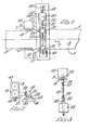
- FIGURE 1 is a plan view of one embodiment of strip edge trimming apparatus;
- FIGURE 2 is a side elevation of the apparatus of Figure 1;
- FIGURE 3 is a partly schematic plan view of a detail associated with the trimmer knives;
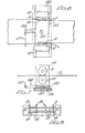
- FIGURE 4 is a sectional elevation of a second preferred embodiment of the invention;
- FIGURE 5 shows respectively plan and side elevational views of an alternative embodiment of trimmer head which is rotatable;
- FIGURE 6 is a plan view, similar to Figure 1, of another embodiment of edge trimmer;
- FIGURE 7 is a sectional elevation of the apparatus of Figure 6, and
- FIGURE 8 is an end elevation showing the apparatus of Figures 6 and 7 modified to slit the strip into three narrow strips, and trim the outside edges.
- Referring to Figures 1 and 2 of the drawings, trimmer apparatus is shown for trimming off the
wavy edges 1 ofmetal strip 3 so as to provide straight edges 5 after the strip has been advanced in the direction of the arrow 7 past the apparatus. - For each edge of the strip a set of upper and
lower trimming knives 9 and 11 is provided, the knives being rotatably mounted about horizontal axes in atrimmer head 13. The two knives of each set are slightly off-set horizontally and vertically with respect to each other and the nip between the knives of each set is arranged to cut off a predetermined width of edge portion of the strip to provide the straight edges 5. The twotrimmer heads 13 are interconnected by atie bar 15 which in the embodiment of Figures 1-3 is located beneath the trimmer heads, thetie bar 15 havingend portions 17 and 19 screw threaded in opposite senses which engage in internally threadedsleeves respective trimmer heads 13 by means ofvertical pivot connections 25, the locations of which correspond with the nip of the knife edges. Thetie bar 15 can be rotated manually or automatically to give fine adjustment to the spacing between the trimmer heads and hence the knives at each edge of the strip. - The
trimmer head 13 is carried by alink 27 which is pivotally connected about avertical axis 29 to a projecting arm on asupport block 31. Thesupport blocks 31 are slidable transverse to the direction of advance of thestrip 3 between a pair ofguides 33 which themselves are supported on acarriage 35. Thesupport blocks 31 are screw threadedly engaged with ascrew shaft 37, the thread associated with-oneblock 31 being of a different sense than that associated with theother block 31. Theshaft 37 is rotated by means of a motor 39 supported on thecarriage 35 so as to move the support blocks and hence the trimmer heads towards or away from each other dependent upon direction of rotation of theshaft 37. - The
carriage 35 is itself mounted for transverse movement relative to the direction of advance of thestrip 3 on afixed base 41 and for this purpose is supported between two sets ofparallel slideways 43. Movement of thecarriage 35 relative to thefixed base 41 is achieved with the aid of a hydraulic jack 45. - As the
strip 3 is advanced in the direction of the arrow 7 so its edge regions, because the strip is not straight but curved over its length, will move from side to side relative to the centre line of the strip if it was centrally orientated with respect to the trimming apparatus. This divergence of the strip from the centre line is sensed by a plurality of sensing devices, e.g. photoelectric cells, located adjacent the edge regions of the strip immediately upstream of the trimming apparatus. The signals received by the sensing. device are converted into an adjustment signal which is passed to the hydraulic jack 45 which is then either extended or retracted so as to move thecarriage 35 in the desired direction to ensure that theknives 9 and 11 maintain contact with the edge regions of the strip and continue their trimming operation. - In the alternative construction shown in Figure 4, like parts have the same reference numerals as Figures 1 and 2. The difference between this construction and that of Figures 1 and 2 is that the
fixed base 41,carriage 35 and the slideways and guideways together with thesupport blocks 31 are all located beneath thetrimmer heads 13, thus providing a-more compact arrangement. Eachsupport block 31 is provided with anextension arm 32 on which the-pivots 29 for thelinks 27 are provided. Furthermore, because theblocks 31 are located beneath theheads 13,support bearings 40 can be provided for eachtrimmer 13. These support bearings may take the form of a simple greased lubricated slideway or they may incorporate rolleI air or similar bearings. In this way, of course,the loads on thepivots 29 are reduced as are the loads on thE links 27. Furthermore, because of the presence of the traversing mechanism beneath the trimmer heads, thetie rod 15 and associated equipment for altering the spacing of the trimmer heads is located above the strip and trimm heads (but not shown). - In a further modification of the invention shown in Figure 5, the support blocks for the trimmer knives 9 BAD ORIGINAL and 11 may be enlarged in size as shown at 42 and may be pivotally supported on
link arms 28 which themselves are connected to thepivots 29. This means that auxiliary sets of trimmingknives knives 9 and 11. When one set of knives becomes worn, theheads 42 can be rotated through 180 and theother trimmer knives - By providing both the
tie rod 15 and theadjustment shaft 37, it is possible to set the distance between the knives of the two sets slightly greater apart than that between theblocks 31. This means that the sets of knives are slightly skewed inwards towards the advancing strip and this means that a good clean cut is achieved during trimming and that the cut-off edge portions of the strip are directed away from the straight edges of the strip as shown in Figure 1. - In the modified construction shown in Figures 6 and 7, like parts have the same reference numerals as in the previous embodiments. However, instead of a linkage mechanism a centre pivot is provided midway between the two sets of
knives 9,11. Theknives 9,11 are rotatably mounted in trimmer heads 13 attached to a sub-base 53. The sub-base 53 is attached to a slidingbase 54 by means of acentral pivot 55. The sub-base 53 and the trimmer knives are pivoted by means of a hydraulic jack or similar device atposition 57 acting on acantilever arm 56 projecting from the sub-base 53. The sub-base 53 and thetrimmer knives 9, 11 are shown in a pivoted position in ghost outline in Figure 6. As in the previous embodiments, once the trimmer knives have been rotated slightly they will be able to traverse across the strip. - Furthermore, means for detecting the edges of the strip are employed and a feed-back signal of strip position to the position of the trimmer is used to control the hydraulic jack or a screw mechanism at
position 57 so as to pivot the trimmer in the correct direction and thus make it move to keep in line with the edges of the strip. As with the previous embodiments, the slidingbase 54 is slidable transversely inslideways 43 on a fixedbase 41. - Figure 8 shows a modified machine arranged to slit strip into three widths and at the same time to remove the edge scrap material. As well as the slitting
knives 9,11, two further sets of knives 78 are supported oncross shafts 79 in support heads 72 mounted on a sub-base 73. The sub-base 73 is pivotally mounted as described above so that the slitter/trimmer can also be made to keep in line with the strip, as in the previous embodiment. - By providing the generally vertical pivots for the slitting or trimming knives, the cutting plane of the knives can be altered very slightly and since the knives act like wheels, once their cutting plane is altered, they will tend to steer themselves, rather like a wheel running on a flat surface, across the
strip 3, and hence there is little resistance to transverse movement of the knives relative to the strip.
Claims (17)
1. Apparatus for trimming the edges of and/or slitting, strip material including at least one knife mounted for rotation about a generally horizontal axis, means to determine the deviation of the strip in the transverse direction from its normal line of advance past said at least one knife and means to move the knife transversely with respect to the normal path of advance of the strip when the strip deviates transversely from that normal path, said knife being pivotally supported about a generally vertical axis so that it can steer itself transversely of the strip.
2. Apparatus according to claim 1 wherein at each knife location, a set of upper and lower knives is provided.
3. Apparatus according to claim 2 wherein the knives are supported on a carriage which is supported on a fixed base for transverse movement relative to the strip and a plurality of sensors is provided to each side of the strip to sense the presence of the edge of the strip, the sensors being connected to a device to move the carriage as desired.
4. Apparatus according to claim 2 or 3 wherein the sets of knives are pivotally supported about vertical axes on support blocks which themselves are mounted in guides on the carriage, the support blocks being movable towards and away from each other in a sense transverse to the direction of advance of the strip to alter the spacing of the knives.
5. Apparatus according to claim 4 wherein the transverse spacing of the knives is achieved by mounting the support blocks on a screw shaft rotatable by means of an electric motor on the carriage, the screw shaft having screw threaded portions of different sense which engage the respective support blocks.
6. Apparatus according to claim 3 or 4 wherein each set of knives is supported in a trimmer head mounted on the end of a pivot link which is pivotally connected to its respective support block about a generally vertical axis.
7. Apparatus according to claim 6 wherein the two trimmer heads are connected together by a transverse tie.
8. Apparatus according to claim 7 wherein the tie comprises a screw rod having end portions screw threaded in opposite senses, these end portions engaging with threaded sleeves which are pivotally connected to the respective trimmer heads.
9. Apparatus according to any one of claims 6 to 8 wherein the fixed base, carriage and support blocks are located beneath the trimmer heads with the pivot for the trimmer heads being carried on an extension arm projecting from the support blocks.
10. Apparatus according to claim 9 when dependent on claim 8 wherein the tie bar is located above the strip on the top of the trimmer heads.
11. Apparatus according to claim 9 or 10 wherein the trimmer heads are supported on a support bearing on top of its respective support block.
12. Apparatus according to any one of the preceding claims 6-11 wherein the trimmer heads are rotatable through at least 180° and carry a spare set of trimmer knives.
13. Apparatus according to claim 1, 2 or 3 wherein the trimmer heads which rotatably support the knife sets are attached to a sub-base which is pivotally supported on a sliding base or carriage which slides in parallel slideways on a- fixed base.
14. Apparatus according to claim 13 wherein a cantilever arm extends outwardly from the sub-base to assist with pivoting the sub-base relative to the sliding base.
15. Apparatus according to claim 13 or 14 wherein the trimmer heads are inter-connected by upper and lower cross shafts on which sets of upper and lower edge trimmer knives and at least one set of upper and lower slitting knives are rotatably mounted.
16. Apparatus according to claim 13 or 14 wherein the trimmer heads are interconnected by upper and lower cross shafts on which a plurality of sets of upper and lower slitting knives only are rotatably mounted.
17. Apparatus according to claim 15 or 16 wherein the slitting knives are adjustable along the cross shafts.
Applications Claiming Priority (2)
| Application Number | Priority Date | Filing Date | Title |
|---|---|---|---|
| GB7922196 | 1979-06-26 | ||
| GB7922196 | 1979-06-26 |
Publications (1)
| Publication Number | Publication Date |
|---|---|
| EP0021821A1 true EP0021821A1 (en) | 1981-01-07 |
Family
ID=10506091
Family Applications (1)
| Application Number | Title | Priority Date | Filing Date |
|---|---|---|---|
| EP80302115A Ceased EP0021821A1 (en) | 1979-06-26 | 1980-06-24 | Apparatus and method for trimming strip material |
Country Status (4)
| Country | Link |
|---|---|
| US (1) | US4358978A (en) |
| EP (1) | EP0021821A1 (en) |
| JP (1) | JPS569116A (en) |
| GB (1) | GB2050915B (en) |
Cited By (4)
| Publication number | Priority date | Publication date | Assignee | Title |
|---|---|---|---|---|
| EP0556462A1 (en) * | 1992-02-15 | 1993-08-25 | Bwg Bergwerk- Und Walzwerk-Maschinenbau Gmbh | Method and apparatus for trimming strips, especially hot-rolled metallic strips |
| EP1306154A1 (en) * | 2001-10-10 | 2003-05-02 | Bwg Bergwerk- Und Walzwerk-Maschinenbau Gmbh | Method and apparatus for trimming bands, more particularly hot-rolled metal bands |
| CN104759778A (en) * | 2015-03-23 | 2015-07-08 | 国家电网公司 | Separation and butt joint lifting mechanism suitable for walking scanning system |
| CN105234972A (en) * | 2015-10-09 | 2016-01-13 | 青岛软控机电工程有限公司 | Deburring device and deburring method thereof |
Families Citing this family (24)
| Publication number | Priority date | Publication date | Assignee | Title |
|---|---|---|---|---|
| US4470555A (en) * | 1982-02-09 | 1984-09-11 | Davy Mckee (Poole) Ltd. | Method and apparatus for winding strip material |
| US4475422A (en) * | 1982-02-26 | 1984-10-09 | Davy Mckee (Poole) Ltd. | Method of slitting or edge trimming strip material |
| DE8207236U1 (en) * | 1982-03-15 | 1982-07-22 | BHS-Bayerische Berg-, Hütten- und Salzwerke AG, 8000 München | DEVICE FOR SUCTIONING THE EDGE STRIPS CUT OFF FROM MATERIAL SHEETS, ESPECIALLY THE EDGE STRIPS OF A CARDBOARD CUT OUT BY LANDING AND CUTTING MACHINES |
| JPS5928412U (en) * | 1982-08-16 | 1984-02-22 | 川崎製鉄株式会社 | Round blade shearing device |
| US4569265A (en) * | 1983-01-04 | 1986-02-11 | Toyo Tire & Rubber Co., Ltd. | Slitter for steel belt |
| DE3400122A1 (en) * | 1984-01-04 | 1985-07-11 | Umlauf, Norbert, 5800 Hagen | CIRCULAR KNIFE UNLOCKING SCISSORS FOR UNLOCKING SEGMENTS AND STRIPS ON METAL BANDS IN TAPE PRODUCTION LINES |
| US4589361A (en) * | 1984-09-28 | 1986-05-20 | Cannon Mills Company | Apparatus and method for automatically guiding, trimming, splitting and side hemming continuous textile material |
| JPH0228384U (en) * | 1988-08-02 | 1990-02-23 | ||
| JPH03136793A (en) * | 1989-10-18 | 1991-06-11 | San Seiki Seisakusho:Kk | Sheet cutting device |
| JP2901413B2 (en) * | 1992-04-22 | 1999-06-07 | 北村機電株式会社 | Stripping device for band material for wound iron core |
| US6202524B1 (en) * | 1996-09-24 | 2001-03-20 | Billco Manufacturing, Inc. | Glass workpiece locating system |
| US6493934B2 (en) | 1996-11-12 | 2002-12-17 | Salman Akram | Method for sawing wafers employing multiple indexing techniques for multiple die dimensions |
| US6250192B1 (en) | 1996-11-12 | 2001-06-26 | Micron Technology, Inc. | Method for sawing wafers employing multiple indexing techniques for multiple die dimensions |
| GB9724335D0 (en) * | 1997-11-19 | 1998-01-14 | Engineering With Excellence Sc | Expandable slotted tube |
| AUPP937199A0 (en) * | 1999-03-22 | 1999-04-15 | Bhp Steel (Ais) Pty Ltd | Handling of metal scrap |
| US6062281A (en) * | 1999-05-13 | 2000-05-16 | U.S. Natural Resources | Vertical arbor saw for shape sawing a log |
| US20020185121A1 (en) * | 2001-06-06 | 2002-12-12 | Farnworth Warren M. | Group encapsulated dicing chuck |
| IT1365619B1 (en) * | 2005-05-27 | 2009-09-11 | Fotoba Int Srl | DEVICE FOR CUTTING PAPER AND OTHER GRAPHIC SUPPORTS IN COIL SIMULTANEOUSLY ON TWO AXES WITH AUTOMATIC CORRECTION OF ERRORS |
| SE530068C2 (en) * | 2006-07-04 | 2008-02-26 | Randek Ab | processing Order |
| US8051757B2 (en) * | 2006-10-25 | 2011-11-08 | Fotoba International S.R.L. | Method for cutting paper and other graphic supports on a roll at the same time along two perpendicular axes with automatic correction of errors |
| JP2011518693A (en) * | 2008-04-23 | 2011-06-30 | ミシュラン ルシェルシュ エ テクニーク ソシエテ アノニム | Method and apparatus for forming a multi-layer tire component |
| JP5356534B2 (en) * | 2008-12-05 | 2013-12-04 | ミシュラン ルシェルシュ エ テクニーク ソシエテ アノニム | Method and apparatus for forming tire components on an axially tapered molding surface |
| CN111941926B (en) * | 2020-08-11 | 2023-03-28 | 山东金泰恒盛新材料科技有限公司 | Stone paper cutting device and cutting method thereof |
| CN115194870B (en) * | 2022-06-14 | 2023-08-01 | 安徽创荣非织造有限公司 | Edge cutting device and method with tension adjusting function for environment-friendly glue-free cotton production |
Citations (9)
| Publication number | Priority date | Publication date | Assignee | Title |
|---|---|---|---|---|
| US2776710A (en) * | 1955-02-10 | 1957-01-08 | Youngstown Ind Inc | Apparatus for processing tenuous material |
| US3080783A (en) * | 1960-09-30 | 1963-03-12 | Allegheny Ludlum Steel | Edge trimmer |
| US3260146A (en) * | 1964-11-30 | 1966-07-12 | Canada Steel Co | Double head side trimmer |
| DE6601125U (en) * | 1966-09-12 | 1969-02-20 | Mannesmann Meer Ag | DEVICE FOR TRIMMING THE STRIPS IN FRONT OF ELECTRIC PIPE WELDING MACHINES |
| US3719114A (en) * | 1971-10-29 | 1973-03-06 | G Vischulis | Web trimmer control |
| US3753381A (en) * | 1971-12-10 | 1973-08-21 | Eickhoff Geb | Web edge control for strip processing lines |
| GB1335477A (en) * | 1972-09-29 | 1973-10-31 | Creban Mfg Co Ltd | Slitting of webs |
| US3774491A (en) * | 1971-06-28 | 1973-11-27 | Armstrong Cork Co | Universal trimming facility |
| DE2341621B2 (en) * | 1973-08-17 | 1977-10-13 | Maschinenfabrik Sack GmbH, 4000 Dusseldorf | DEVICE FOR CONTROL OF STRAP CENTER POSITION IN FRONT OF A STRIP PROCESSING MACHINE, FOR EXAMPLE OF A CIRCULAR CUTTER |
Family Cites Families (7)
| Publication number | Priority date | Publication date | Assignee | Title |
|---|---|---|---|---|
| US3110208A (en) * | 1960-11-07 | 1963-11-12 | Reynolds Metals Co | Apparatus for trimming marginal edges of metal strip and for chopping marginal trimmings |
| US3176567A (en) * | 1961-05-15 | 1965-04-06 | Owens Illinois Glas Company | Slitter machine with automatic edge control |
| US3262650A (en) * | 1964-11-12 | 1966-07-26 | Allegheny Ludlum Steel | Means for laterally positioning roll of web material relative to slitter blades |
| US3513743A (en) * | 1967-08-21 | 1970-05-26 | Nat Steel Corp | Multiple-head slitting apparatus |
| US3550490A (en) * | 1968-06-10 | 1970-12-29 | Phillips Petroleum Co | Multiple cutting apparatus for elongated articles |
| US3776072A (en) * | 1971-02-26 | 1973-12-04 | Gerber Garment Technology Inc | Method and apparatus for cutting sheet material |
| US3727503A (en) * | 1971-11-26 | 1973-04-17 | Braner Eng Inc | Slitter having pivotal multiple spaced pairs of arbors |
-
1980
- 1980-06-17 US US06/160,280 patent/US4358978A/en not_active Expired - Lifetime
- 1980-06-24 EP EP80302115A patent/EP0021821A1/en not_active Ceased
- 1980-06-24 GB GB8020703A patent/GB2050915B/en not_active Expired
- 1980-06-25 JP JP8636680A patent/JPS569116A/en active Pending
Patent Citations (9)
| Publication number | Priority date | Publication date | Assignee | Title |
|---|---|---|---|---|
| US2776710A (en) * | 1955-02-10 | 1957-01-08 | Youngstown Ind Inc | Apparatus for processing tenuous material |
| US3080783A (en) * | 1960-09-30 | 1963-03-12 | Allegheny Ludlum Steel | Edge trimmer |
| US3260146A (en) * | 1964-11-30 | 1966-07-12 | Canada Steel Co | Double head side trimmer |
| DE6601125U (en) * | 1966-09-12 | 1969-02-20 | Mannesmann Meer Ag | DEVICE FOR TRIMMING THE STRIPS IN FRONT OF ELECTRIC PIPE WELDING MACHINES |
| US3774491A (en) * | 1971-06-28 | 1973-11-27 | Armstrong Cork Co | Universal trimming facility |
| US3719114A (en) * | 1971-10-29 | 1973-03-06 | G Vischulis | Web trimmer control |
| US3753381A (en) * | 1971-12-10 | 1973-08-21 | Eickhoff Geb | Web edge control for strip processing lines |
| GB1335477A (en) * | 1972-09-29 | 1973-10-31 | Creban Mfg Co Ltd | Slitting of webs |
| DE2341621B2 (en) * | 1973-08-17 | 1977-10-13 | Maschinenfabrik Sack GmbH, 4000 Dusseldorf | DEVICE FOR CONTROL OF STRAP CENTER POSITION IN FRONT OF A STRIP PROCESSING MACHINE, FOR EXAMPLE OF A CIRCULAR CUTTER |
Non-Patent Citations (1)
| Title |
|---|
| PATENTS ABSTRACTS OF JAPAN, vol. 1, no. 68, 4 July 1977, page 1121, M-77; & JP-A-52 016 083 * |
Cited By (5)
| Publication number | Priority date | Publication date | Assignee | Title |
|---|---|---|---|---|
| EP0556462A1 (en) * | 1992-02-15 | 1993-08-25 | Bwg Bergwerk- Und Walzwerk-Maschinenbau Gmbh | Method and apparatus for trimming strips, especially hot-rolled metallic strips |
| US5381342A (en) * | 1992-02-15 | 1995-01-10 | Bwg Bergwerk- Und Walzwerk- Maschinenbau Gmbh | System for trimming a continuously moving metal strip |
| EP1306154A1 (en) * | 2001-10-10 | 2003-05-02 | Bwg Bergwerk- Und Walzwerk-Maschinenbau Gmbh | Method and apparatus for trimming bands, more particularly hot-rolled metal bands |
| CN104759778A (en) * | 2015-03-23 | 2015-07-08 | 国家电网公司 | Separation and butt joint lifting mechanism suitable for walking scanning system |
| CN105234972A (en) * | 2015-10-09 | 2016-01-13 | 青岛软控机电工程有限公司 | Deburring device and deburring method thereof |
Also Published As
| Publication number | Publication date |
|---|---|
| GB2050915A (en) | 1981-01-14 |
| JPS569116A (en) | 1981-01-30 |
| US4358978A (en) | 1982-11-16 |
| GB2050915B (en) | 1982-12-01 |
Similar Documents
| Publication | Publication Date | Title |
|---|---|---|
| US4358978A (en) | Trimming strip material | |
| US4127044A (en) | For sawing and for controlling the sawing process | |
| US4144782A (en) | Apparatus for curved sawing of timber | |
| US5007318A (en) | Metal strip edge trimming apparatus | |
| IE45615B1 (en) | Machines for the formation of grooves and recesses in the treads of new or retreaded tyres | |
| US4475422A (en) | Method of slitting or edge trimming strip material | |
| US4501177A (en) | Edge trimming and scrap disposal system | |
| US4638701A (en) | Shears, especially circular knife shears | |
| US3993231A (en) | Tube cutting apparatus | |
| CA2088183C (en) | System for trimming continuously moving metal strip | |
| GB1355877A (en) | Machine for cutting and winding up webs of sheet material | |
| GB2163381A (en) | Removing strips from paper webs | |
| US5400843A (en) | Apparatus for controlling the taper of wood boards formed by a chipless cutting operation | |
| CA1103580A (en) | Device for cutting material longitudinally into strips | |
| US2417556A (en) | Trimming apparatus | |
| EP0190665B1 (en) | Machine for working veneer sheets | |
| EP0732286B1 (en) | Roller conveyor upstream of the pinch-roll of the winder of a hot strip rolling train | |
| US20220016798A1 (en) | Cutting machine for paper rolls with a sharpening device | |
| US4523364A (en) | High speed production of multiple gauge strip | |
| US4625605A (en) | Automatic knife alignment for shear | |
| US4059472A (en) | Coated products | |
| US3476000A (en) | Strip shearing apparatus | |
| US2940350A (en) | Plural slitter cutters and the mounting means therefor | |
| KR100775468B1 (en) | Burr removing apparatus for the edge of the strip | |
| US5158000A (en) | Two-shaft method for slicing a cylindrical elastic body into rings and its apparatus |
Legal Events
| Date | Code | Title | Description |
|---|---|---|---|
| PUAI | Public reference made under article 153(3) epc to a published international application that has entered the european phase |
Free format text: ORIGINAL CODE: 0009012 |
|
| AK | Designated contracting states |
Designated state(s): AT BE DE FR GB IT LU NL SE |
|
| 17P | Request for examination filed |
Effective date: 19810616 |
|
| STAA | Information on the status of an ep patent application or granted ep patent |
Free format text: STATUS: THE APPLICATION HAS BEEN REFUSED |
|
| 18R | Application refused |
Effective date: 19830823 |
|
| RIN1 | Information on inventor provided before grant (corrected) |
Inventor name: LAWSON, KENNETH THOMAS |