EP0021237B1 - Apparatus for applying connectors to multiconductor flat cable - Google Patents
Apparatus for applying connectors to multiconductor flat cable Download PDFInfo
- Publication number
- EP0021237B1 EP0021237B1 EP80103226A EP80103226A EP0021237B1 EP 0021237 B1 EP0021237 B1 EP 0021237B1 EP 80103226 A EP80103226 A EP 80103226A EP 80103226 A EP80103226 A EP 80103226A EP 0021237 B1 EP0021237 B1 EP 0021237B1
- Authority
- EP
- European Patent Office
- Prior art keywords
- connector
- cable
- holding member
- disposed
- magazines
- Prior art date
- Legal status (The legal status is an assumption and is not a legal conclusion. Google has not performed a legal analysis and makes no representation as to the accuracy of the status listed.)
- Expired
Links
- 230000007246 mechanism Effects 0.000 claims abstract description 32
- 238000005520 cutting process Methods 0.000 claims description 14
- 238000003780 insertion Methods 0.000 abstract description 3
- 230000037431 insertion Effects 0.000 abstract description 3
- 239000012530 fluid Substances 0.000 description 9
- 238000009413 insulation Methods 0.000 description 3
- 238000000034 method Methods 0.000 description 3
- 230000002441 reversible effect Effects 0.000 description 3
- 239000004020 conductor Substances 0.000 description 2
- 238000006073 displacement reaction Methods 0.000 description 2
- 230000000717 retained effect Effects 0.000 description 2
- 230000000712 assembly Effects 0.000 description 1
- 238000000429 assembly Methods 0.000 description 1
- 230000000903 blocking effect Effects 0.000 description 1
- 230000000295 complement effect Effects 0.000 description 1
- 238000004519 manufacturing process Methods 0.000 description 1
- 238000005065 mining Methods 0.000 description 1
- 238000003825 pressing Methods 0.000 description 1
Images


Classifications
-
- H—ELECTRICITY
- H01—ELECTRIC ELEMENTS
- H01R—ELECTRICALLY-CONDUCTIVE CONNECTIONS; STRUCTURAL ASSOCIATIONS OF A PLURALITY OF MUTUALLY-INSULATED ELECTRICAL CONNECTING ELEMENTS; COUPLING DEVICES; CURRENT COLLECTORS
- H01R43/00—Apparatus or processes specially adapted for manufacturing, assembling, maintaining, or repairing of line connectors or current collectors or for joining electric conductors
- H01R43/01—Apparatus or processes specially adapted for manufacturing, assembling, maintaining, or repairing of line connectors or current collectors or for joining electric conductors for connecting unstripped conductors to contact members having insulation cutting edges
-
- Y—GENERAL TAGGING OF NEW TECHNOLOGICAL DEVELOPMENTS; GENERAL TAGGING OF CROSS-SECTIONAL TECHNOLOGIES SPANNING OVER SEVERAL SECTIONS OF THE IPC; TECHNICAL SUBJECTS COVERED BY FORMER USPC CROSS-REFERENCE ART COLLECTIONS [XRACs] AND DIGESTS
- Y10—TECHNICAL SUBJECTS COVERED BY FORMER USPC
- Y10T—TECHNICAL SUBJECTS COVERED BY FORMER US CLASSIFICATION
- Y10T29/00—Metal working
- Y10T29/49—Method of mechanical manufacture
- Y10T29/49002—Electrical device making
- Y10T29/49117—Conductor or circuit manufacturing
- Y10T29/49174—Assembling terminal to elongated conductor
-
- Y—GENERAL TAGGING OF NEW TECHNOLOGICAL DEVELOPMENTS; GENERAL TAGGING OF CROSS-SECTIONAL TECHNOLOGIES SPANNING OVER SEVERAL SECTIONS OF THE IPC; TECHNICAL SUBJECTS COVERED BY FORMER USPC CROSS-REFERENCE ART COLLECTIONS [XRACs] AND DIGESTS
- Y10—TECHNICAL SUBJECTS COVERED BY FORMER USPC
- Y10T—TECHNICAL SUBJECTS COVERED BY FORMER US CLASSIFICATION
- Y10T29/00—Metal working
- Y10T29/51—Plural diverse manufacturing apparatus including means for metal shaping or assembling
- Y10T29/5136—Separate tool stations for selective or successive operation on work
- Y10T29/5137—Separate tool stations for selective or successive operation on work including assembling or disassembling station
-
- Y—GENERAL TAGGING OF NEW TECHNOLOGICAL DEVELOPMENTS; GENERAL TAGGING OF CROSS-SECTIONAL TECHNOLOGIES SPANNING OVER SEVERAL SECTIONS OF THE IPC; TECHNICAL SUBJECTS COVERED BY FORMER USPC CROSS-REFERENCE ART COLLECTIONS [XRACs] AND DIGESTS
- Y10—TECHNICAL SUBJECTS COVERED BY FORMER USPC
- Y10T—TECHNICAL SUBJECTS COVERED BY FORMER US CLASSIFICATION
- Y10T29/00—Metal working
- Y10T29/51—Plural diverse manufacturing apparatus including means for metal shaping or assembling
- Y10T29/5193—Electrical connector or terminal
-
- Y—GENERAL TAGGING OF NEW TECHNOLOGICAL DEVELOPMENTS; GENERAL TAGGING OF CROSS-SECTIONAL TECHNOLOGIES SPANNING OVER SEVERAL SECTIONS OF THE IPC; TECHNICAL SUBJECTS COVERED BY FORMER USPC CROSS-REFERENCE ART COLLECTIONS [XRACs] AND DIGESTS
- Y10—TECHNICAL SUBJECTS COVERED BY FORMER USPC
- Y10T—TECHNICAL SUBJECTS COVERED BY FORMER US CLASSIFICATION
- Y10T29/00—Metal working
- Y10T29/53—Means to assemble or disassemble
- Y10T29/5313—Means to assemble electrical device
- Y10T29/532—Conductor
- Y10T29/53209—Terminal or connector
- Y10T29/53213—Assembled to wire-type conductor
- Y10T29/53217—Means to simultaneously assemble multiple, independent conductors to terminal
-
- Y—GENERAL TAGGING OF NEW TECHNOLOGICAL DEVELOPMENTS; GENERAL TAGGING OF CROSS-SECTIONAL TECHNOLOGIES SPANNING OVER SEVERAL SECTIONS OF THE IPC; TECHNICAL SUBJECTS COVERED BY FORMER USPC CROSS-REFERENCE ART COLLECTIONS [XRACs] AND DIGESTS
- Y10—TECHNICAL SUBJECTS COVERED BY FORMER USPC
- Y10T—TECHNICAL SUBJECTS COVERED BY FORMER US CLASSIFICATION
- Y10T29/00—Metal working
- Y10T29/53—Means to assemble or disassemble
- Y10T29/5313—Means to assemble electrical device
- Y10T29/53252—Means to simultaneously fasten three or more parts
Definitions
- This invention pertains to apparatus for substantially automatically assembling connector devices of the insulation piercing terminal type to multiconductor flat electrical cable.
- the present invention provides an apparatus for applying a two part electrical connector to a flat multiconductor cable at either or both ends thereof, as well as selected positions between the cable ends.
- the connector applying apparatus contains a frame, a mechanism for feeding a predetermined length of cable along a predetermined path on the frame, an engaging mechanism for engaging and moving the connector parts toward each other to be applied to the cable, magazines for holding a plurality of each of the connector parts, and transferring mechanism for transferring the connector parts from the magazines prior to their application to the cable.
- a central feature of the invention is a connector holding member for use with the above-listed elements of the connector applying apparatus for holding the connector parts spaced apart one from the other so that the connector parts are disposed on opposite sides of the cable.
- the holding member includes a pair of slots aligned in such a way as to receive the connector parts (a connector body and a connector cover) spaced apart one from the other.
- a third slot is formed in the holding member between the pair of aligned slots and is substantially perpendicular thereto. A portion of the cable is received into the third slot when the holding member is moved in a direction parallel to the line of intersection of the slots into position for applying the connector body and connector cover to the cable.
- the apparatus of the present invention is adapted to apply a connector of the general type shown in Fig. 2 to multi conductor flat cable also shown in Fig. 2 and generally designated by the numeral 24.
- the connector shown in Fig. 2 includes a body part 26 on which are mounted a plurality of closely spaced insulation displacement terminals 27.
- the connector shown in Fig. 2 also includes a cover part 28 having elongated slots, not shown, for receiving the ends of the terminals 27.
- the cover 28 is also provided with clips 30 disposed at the bottom of respective grooves 31 at opposite ends of the cover.
- the clips 30 are operable to project into cooperative grooves 32 in the ends of the body 26 to align and hold the body and cover parts in assembly.
- One side of the cover 28 includes an elongated shallow recess 34 into which the cable may be folded and held against the top of the cover by a strain relief member 36.
- the strain relief member 36 includes a pair of deflectable arms 37 which are adapted to hold the strain relief member in assembly with the other parts of the connector with the cable clamped therebetween in a known way.
- the general type of connector shown in Fig. 2 is well known and various specific types are known which differ in certain detailed respects.
- the specific type of connector shown in Fig. 2 is one of the Scotchflex brand connectors manufactured by the Minnesota Mining and Manufacturing Company, St. Paul, Minnesota.
- the apparatus of the present invention includes a frame 42 (see Fig. 3 also) which is shown mounted on a cabinet 44 which may house some of the control circuitry for operating the apparatus.
- the frame 42 is adapted to support a cable feeding unit 46 which is characterized by a pair of motor driven rollers 48 and 50 spaced closely adjacent to each other and engageable with the multiconductor flat cable 24 which may be supplied to the apparatus 40 from a source such as a relatively large roll or the like, not shown.
- the apparatus 40 also includes spaced apart cable clamp and transfer units designated generally by the numerals 51 and 52.
- the cable clamp and transfer units 51 and 52 which will be explained in further detail herein, are operable to position the respective ends of the cable for application of connectors thereto.
- the frame 42 also supports elongated magazines 54, and 56 which are aligned with each other on opposite sides of a connector holding member comprising a generally cylindrical shaft designated by numeral 58.
- the magazines 54 and 56 are adapted to hold a plurality of connector covers side by side.
- the frame 42 also supports a magazine 60 disposed above the magazine 54 for holding a plurality of connector bodies side by side.
- the connector holding shaft 58 is operable to be moved from the position shown wherein connector body and cover parts may be inserted in the shaft to a position wherein the shaft 58 is interposed in the path of the cable 24 and the connector parts may be applied to the cable.
- the frame 42 includes a bridge portion 62 which includes vertical support plates 63 and 65 and which supports an actuator 64 for loading the connector bodies into the shaft 58 and an actuator 66 for pressing the connector bodies into assembly with a portion of the cable.
- the bridge portion 62 also supports an actuator 68 which is operable to eject finished cable assemblies from the apparatus 40.
- Fig. 3 the cable feed unit 46 is shown in section view taken from the centerline of the cable feed path.
- the rollers 48 and 50 of the cable feed unit are rotatably journalled in suitable bearings which are mounted in spaced apart upstanding supports 70 and 72.
- the rollers 48 and 50 are drivably engaged with each other by respective gears 74 and 76 and the roller 50 is directly connected to an electric motor 78 which is desirably one which is responsive to rotate a predetermined amount when energized by a pulse type electrical signal and is precisely braked when deenergized.
- Such motors are commonly known as stepping motors.
- the bearings supporting the roller 48 are mounted on a shaft 80 which is disposed in blocks 82 and 84 which are movable in vertical slots, not shown, in the brackets 70 and 72 and are spring biased to move the roller 48 toward the roller 50 to forcibly engage the cable 24 disposed between the rollers. Accordingly, when the rollers 48 and 50 are rotated the cable 24 is fed therebetween a linear amount proportional to the angular rotation of the rollers.
- the cable feed unit 46 also includes cable guides 86 and 88, disposed on transverse supports 90 and 92 and on opposite sides of the rollers 48 and 50, as shown by way of example for the guides 86, in Fig. 3.
- the guides 86 and 88 are removably mounted on the supports 90 and 92 and may be adjusted relative to each other laterally to accommodate different cable widths.
- the cable clamp unit 51 includes a support member 94 which is mounted on a pair of spaced apart cylindrical rails 96 and 98 by means of linear bearings 100.
- the rails 96 and 98 are supported by the member 90 and a base member 99 for a cable cutting mechanism to be described further herein.
- the support 94 is connected to a pressure fluid cylinder type actuator 102 which is mounted under the transverse members 90 and 92 of the cable feed unit.
- An extensible piston rod 104 of the actuator 102 is suitably connected at its distal end to clamp unit 51.
- the clamp unit 51 includes a movable cable clamping jaw 106 which is connected to the piston rod of a pressure fluid actuator 108 mounted on top of a supporting bridge 110.
- the actuator 108 is operable to releasably clamp the cable between the jaw 106 and a surface 112 on the support 94.
- the actuator 102 is operable to move the cable clamp unit 51 from the position shown in Fig. 3 toward the connector holding shaft 58 to precisely position the leading edge of the cable in the holding shaft for application of a connector to the cable.
- the apparatus 40 also includes the aforementioned cable cutting mechanism which is shown in Fig. 3 and 6.
- the cable cutting mechanism includes the base member 99 upon which is removable mounted an anvil support plate 114 which supports an anvil 116.
- the support plate 114 is adapted to support spaced apart cable guides 118 and 120 in one of a plurality of selected positions depending on the width of the cable.
- the cable guides 118 and 120 are similar to the guides 86 and 88 on the cable feed unit 46.
- a pressure fluid cylinder type actuator 122 mounted on the bridge 62, is operable to extend and retract a piston rod 124 connected to a cable cutting blade holder 126 in which is mounted a cutting blade 128.
- the blade holder 126 is guided for reciprocating movement by spaced apart guide pins 127 mounted on the base 99, and the blade holder is biased into the retracted positon by coil springs 129 disposed around the pins 127.
- the actuator 122 is operable to extend the holder 126 to cause the blade 128 to cut a length of cable 24 disposed between the guides 118 and 120.
- the cable clamp and transfer unit 52 is disposed beyond the holding shaft 58 in the direction of movement of a length of cable 24 as it is prepared by the apparatus.
- the clamp unit 52 includes a housing 130 which is slidably supported on spaced apart rails 132 and 134 mounted on the frame 42.
- the housing 130 is connected to the piston rod 136 of a double acting cylinder actuator 138 which is mounted on the frame 42, as shown in Fig. 3.
- the cable clamp unit 52 is further characterized by double acting cylinder actuator means comprising cylinder bores 140, 142, and 144. Pistons 146 and 148 are disposed in the respective bores 140 and 144 and are connected to an upper clamp jaw 150.
- a piston 152 is disposed in the bore 142 and is connected to a lower clamp jaw 154.
- the piston rod 136 is extended to position the clamp unit 52 adjacent to the holding shaft 58 for receiving the trailing end portion of a length of cable.
- the jaws 150 and 154 have been retracted away from each other to permit removal of a cable, not shown, with a connector applied to its trailing end or to permit feeding of the leading end of a length of cable, with a connector applied thereto away from the holding shaft 58.
- the clamp unit 52 is operable to clamp the cable after the leading end of the cable has been moved to the right, viewing Fig. 3, to establish the predetermined length of cable, and prior to cutting the cable to form the trailing end.
- An adjustable stop 156 is mounted on the housing 130 and is engageable with a bumper 158 mounted on the frame 42.
- a plate 160 fastened to the housing 130 is provided for supporting the cable as it is fed past the clamp unit 52 and onto a second cable supporting plate 162.
- the connector holding shaft 58 is mounted in a housing 166 fastened to the bridge member 63.
- the holding shaft 58 includes an elongated slot 170 formed through the central axis of the shaft and opening to the distal end thereof.
- the slot 170 is formed perpendicular to two aligned slots 172 and 174 which are disposed on opposite sides of the slot 170.
- the slots 172 and 174 include means disposed therein for receiving and holding a connector body 26 and cover 28, respectively.
- the connector body and cover holding means will be explained in further detail herein.
- the holding shaft 58 is operable to move between the position shown by the solid lines in Fig. 7 and a position illustrated by the dashed lines in Fig. 7.
- the slot 172 is aligned with a recess 176 formed in the magazine 60 which permits a ram 178 connected to the actuator 64 to push a connector body 26 into the slot.
- the connector body which is in position to be loaded into the holding shaft 58 is urged by mechanism to be described against a stop 177 while it is still in the magazine 60.
- the slot 174 is also aligned with an opening between the magazines 54 and 56 for receiving a connector cover 28 from one or the other of the magazines. As shown in Fig.
- the ram 178 is guided for reciprocating movement in a vertical plane by spaced apart guide rods 182.
- a similar retractable ram 184 is disposed below the magazines 54 and 56 and is guided for vertical movement in the same plane as the ram 178 by guide rods 186.
- the ram 184 which is particularly adapted to engage and hold a connector cover 28 of the type shown in Fig. 2, includes spaced apart upwardly extending projections 187 which are operable to extend into the grooves 31 of the opposite ends of the covers for maintaining proper alignment of the cover.
- the ram 184 is connected to a pressure fluid cylinder type actuator 188.
- the shaft When a connector body and cover member have been loaded into the holding shaft 58, the shaft is actuated to be extended to the dashed line position shown in Fig. 7. In the extended position of the holding shaft 58 the cable 24 normally extends into or through the slot 170.
- the slots 172 and 174 are also respectively aligned with opposed rams 190 and 192, shown in their retracted position in Fig. 7.
- the ram 190 is connected to the cylinder actuator 66 and is guided by spaced apart guide rods 194 for reversible linear movement in a vertical plane.
- the ram 192 is also connected to a cylinder actuator 196 mounted under the frame 42 and is guided for reversible linear movement by rods 198.
- the ram 192 as well as the ram 190 may be formed to have interchangeable members having respective recesses 200 and 202 for engaging a particular shape of connector part in accordance with the type of connector being applied by the apparatus 40.
- the ram 192 is actuated to move upward, viewing Fig. 7, to engage a connector cover 28 disposed in the slot 174 and move the cover into position directly under and engageable by the cable 24.
- the ram 190 is then actuated to move downward, viewing Fig. 7, to engage and press a connector body 26 into engagement with the cable 24 and the clips 30 of the connector cover to assemble the connector to the cable.
- the shaft 58 is retracted to the position represented by the solid lines of Fig. 7 and the rams 190 and 192 are subsequently retracted to the positions shown in Fig. 7.
- the cable is then advanced by the feed mechanism 46 or is ejected by the actuator 68 if the operation involved applying a connector to the trailing end of the cable.
- the covers 28 For application of connectors of the type shown in Fig. 2 to the cable ends, it is necessary that the covers 28 be arranged so that the recess 34 is facing in a direction to receive the cable when the cable is folded over the top of the cover prior to application of the strain relief member 36. Accordingly, the covers 28 must be loaded into one or the other of the magazines 54 or 56 such that the recesses 34 of adjacent covers are facing in the opposite direction. Alternatively, covers 28 are loaded into one magazine with the recesses 34 facing in one direction and covers are also loaded into the other of the magazines 54 and 56 with the recesses facing in the opposite direction.
- a cover 28 from the magazine 54 or 56 for insertion into the holding shaft 58 is provided by mechanism shown in Figs. 10 and 18.
- two spaced apart support fingers 204 are mounted on a magazine support plate 206 and extend across the opening between magazines 54 and 56 for supporting covers which are moved into positions for insertion into the holding shaft 58.
- the cover loading ram 184 as shown in Fig. 7, has channels 208 and 210 therein to provide clearance around the fingers 204 when the ram is actuated to insert a cover 28 into the holding shaft 58.
- the magazine selector mechanism includes a gate characterized by an inverted U-shaped member 212, as shown also in Fig. 7, which extends across the end of the magazine 56 in the position shown in Fig. 18.
- the gate 212 is connected to a pressure fluid cylinder type actuator 214 mounted under the magazine 54.
- the piston rod 218 of the actuator 214 is connected to an intermediate member 216 which is connected to the gate 212.
- Spaced apart guide rods 220 extend from the member 216 into complementary bores in a mounting block 222 for the actuator 214.
- the actuator 214 is operable to move the gate 212 from the position shown in Fig. 10 blocking the feeding of cover parts from the magazine 56 to a position abutting the end of magazine 54 to block the feeding of cover parts from the magazines 54.
- a similar mechanism and second magazine could, of course, be provided and arranged in a similar way with respect to the magazine 60 for selection of the connector bodies, if desired.
- the housing 166 includes an interior bore 226 in which is disposed a tubular sleeve 228 supported for rotation on bearings 230.
- the holding shaft 58 is mounted in the sleeve 228 and is slidable with respect to the sleeve in opposite directions along the longitudinal coincident central axes of the shaft and sleeve.
- the sleeve 228 includes two spaced apart keys 232 which project into a key slot 234 formed in the shaft 58 whereby the shaft is longitudinally slidable but nonrotatable with respect to the sleeve.
- the end of the shaft 58 opposite that which includes the slot 170 is provided with an arm 236 connected to the piston rod 238 of a pressure fluid linear actuator formed by a piston 240 disposed for reciprocation in a bore 242 in the housing 166.
- the arm 236 includes an adjustable stop 244 engageable with the housing 166 for adjustment of the extended position of the shaft 58 shown by the dashed lines in Fig. 7.
- a collar 246 mounted on the end of the shaft 58 is adapted to engage spaced apart electrical switches 248 and 250 mounted on a bracket 252 fastened to the housing 166.
- the sleeve 228 includes an integrally formed gear portion 254 which is meshed with a gear rack 256 disposed for linear reciprocating movement in the housing 166 in directions perpendicular to the longitudinal axis of the shaft 58.
- An arm 258 connected to one end of the rack 256 is also connected to the piston rod 260 of a pressure fluid cylinder type actuator 262 mounted on the housing 166.
- the actuator 262 is operable to drive the rack 256 in opposite directions to reversibly rotate the sleeve 228 and shaft 58.
- An adjustable stop 264 is mounted on the arm 258 for limiting the rotary position of the shaft 58 in one direction of rotation.
- a collar 266 mounted on the rack 256 is operable to engage a pair of spaced apart switches 268 amd 270, as shown in Fig. 11.
- the slots 172 and 174 are provided with respective sets of connector part gripping jaws 272 and 274.
- the jaws 272 are detachably secured to the shaft 58 by fasteners 276.
- the jaws 274 are retained on the shaft 58 by suitable fasteners 278 and are biased toward the jaws 272 by springs 280 interposed between the jaws 274 and a side wall of the slots 172 and 174. Accordingly, the jaws 274 may be yieldably biased into engagement with the connector cover and body parts, respectively, to hold the parts in the shaft 58 until the connector is applied to the cable and the shaft is retracted away from the cable.
- Fig. 15 illustrates a transverse elevation of the magazines 54 and 60 and the supporting structure therefor.
- the magazine 60 comprises an elongated tray 288 including spaced apart guides 290 adapted to retain a plurality of connector bodies 26 on the magazine side by side.
- the magazine 60 is removably supported on the apparatus 40 by structure comprising spaced apart support members 292 and 294, as shown in Fig. 1, to which are fixed elongated magazine retaining rails 296.
- the magazine 60 is thus slidably supported by the rails 296 for removal from the apparatus when empty or when a replacement magazine is to be placed on the apparatus 40.
- the magazine 54 is also characterized by an elongated tray 297 which is removably disposed on a support plate 298 mounted on the frame 42 and also including spaced apart magazine retaining rails 300.
- the tray 297 is adapted to support a plurality of connector covers 28 side by side and retained on the magazine by spaced apart guides 302.
- the second connector cover magazine 56 disposed opposite the magazine 54, is also removably supported on the plate 206 mounted on the frame 42.
- the magazine 56 also includes an elongated tray 304 adapted to support a plurality of connector covers 28 side by side between spaced apart guides 306.
- the tray 304 is disposed between oppositely facing guide rails 308.
- the tray 304 includes a recess 305 which provides clearance for the connector cover support fingers 204. The top surfaces of the fingers 204 are even with the top surface of the tray 304.
- the magazines 54 and 60 are respectively provided with movable pusher plates 312 and 314 which feed the connector parts toward the holding shaft 58 for subsequent loading thereinto.
- the pusher plate 312 is connected to a bracket assembly 376 by means of a spring biased hinge 317 so that the plate may be moved clear of the magazine 54 to permit loading and unloading of the magazine tray 297 with respect to the apparatus 40.
- the bracket 316 has mounted thereon spaced apart cylindrical rollers 318 which are each provided with a circumferential recess to provide for retaining the rollers between spaced apart tracks 320 mounted on the apparatus 40.
- the tracks 320 extend parallel to the magazines 54 and 60 to permit movement of the pusher plate 312 substantially the full length of the magazine 54.
- the pusher plate 314 is similarly mounted on hinge 317 which is connected to a bracket 322.
- the bracket 322 is guided for movement along the magazine 60 by a pair of rollers 318 mounted on the bracket and engaged with a second set of tracks 320 mounted above the tracks which guide the pusher plate 312.
- the magazine 56 is also provided with a hinged pusher plate 326 for moving the connector covers toward the holding shaft 58.
- the pusher plate 326 is mounted on a bracket 328 similar to the brackets 316 and 322 and which is similarly mounted for guided movement along spaced apart parallel tracks 330.
- the pushes plates 312, 314, and 326 are biased into engagement with the connector parts disposed in the respective magazines 54, 60, and 56 by mechanism which provides a substantially constant feed or bias force on the connector parts disposed in the magazines regardless of the number of parts remaining in the respective magazines at any one time.
- the bracket 312 is shown connected to a flexible cable 332 which is trained over a sheave 334 mounted on the vertical support plate 63.
- the opposite end of the cable 332 is connected to a hanging weight 336.
- the brackets 322 and 328 are also connected to flexible cables 338 and 340, respectively.
- the cable 340 is connected to a weight 342 and is trained over a sheave mounted next to sheave 334, not shown, and sheaves 344 and 346 to provide for spacing the weight 342 from the weight 336.
- the cable 338 is similarly trained over sheaves 348, 350, 352, and 354 and is connected to a weight 356. Since the weights 336, 342, and 356 exert a constant downward force on the cables, the feed force exerted by the respective pusher plates remains substantially constant regardless of the number of connector members remaining in the magazines.
- the apparatus 40 may be operated in a preferred mode by a suitable electrical control system comprising electrical proximity or limit switches, some of which are illustrated in the drawings, together with time delay devices and logic devices which are operable to actuate solenoid valves for supplying pressure fluid to the various actuators included in the apparatus in a predetermined sequence.
- a control system also would preferably include a control circuit for energizing the motor 78 of the cable feed unit 46 to feed a predetermined amount of cable through the apparatus.
- An operating cycle would commence with energization of the actuators 64 and 188 to cause the respective rams 178 and 184 to insert a connector cover and body into the slots 172 and 174 in the holding shaft 58.
- the rams 178 and 184 are then retracted and pressure fluid is introduced into the bore 242 to cause piston 240 to move the shaft 58 to the position represented by the dashed lines in Fig. 7.
- the cable clamp 106 is actuated to clamp the cable.
- the cylinder actuator 102 is actuated to move the clamp unit 51 to the right, viewing Fig. 3, from the position shown so that the leading end of the cable is inserted into the holding shaft slot 170 between the connector cover and body parts 26 and 28.
- the actuator 196 When the cable is positioned in the holding shaft 58 the actuator 196 is energized to move the ram 192 upward to move the connector cover up to the cable and provide support for the cover. The actuator 66 is then sequentially energized to cause the ram 190 to press the connector body into engagement with the cable and the connector cover to complete the assembly process.
- the holding shaft linear movement actuator is caused to retract the holding shaft 58 to the position shown by the solid lines in Fig. 7.
- the rams 190 and 192 and the clamp jaw 106 are also subsequently retracted after a short time delay.
- the feed motor 78 is then energized by a predetermined repeating pulse signal which varies in accordance with the length of cable to be fed to thereby cause the feed unit 46 to feed a predetermined length of cable past the cutting blade 128.
- the actuator 102 returns the clamp unit 51 to the position shown in Fig.
- the actuator 214 moves the gate 212 so that a connector cover having its recess turned opposite to that of the cover previously applied may be positioned for loading into the holding shaft 58. If a connector is to be applied intermediate the ends of the length of cable being prepared or if connector covers without special nonsymmetric configuration were being used, actuation of the gate would not be necessary until one of the magazines was empty.
- the rams 178 and 184 are actuated to load another connector into the holding shaft 58.
- the cable clamp unit 52 is actuated to cause jaws 150 and 154 to move together clamping the cable therebetween.
- the holding shaft 58 is then subsequently moved into the connector application position.
- the actuator 122 is energized to cut the cable and then deenergized to cause the cutting blade 128 to retract to the noncutting position.
- a limit switch is actuated which provides for operation of the actuator 138 to move the clamp unit 52 to the right, viewing Fig. 3, to place the trailing end of the cable in position for application of the connector thereto. Movement of the clamp unit 52 to the limit position will actuate a suitable limit switch, not shown, which causes sequential actuation of the rams 192 and 190 as described previously to apply the connector to the trailing end of the cable. The holding shaft 58 is then retracted and the clamp jaws 150 and 154 are released.
- the control circuit would cause the actuator 262, Fig. 12, to rotate the holding shaft 58 after the connector parts were loaded into the slots 172 and 174 and the loading rams were retracted to cause the connector body and cover positions to be interchanged and inverted with respect to their positions upon being loaded in the holding shaft.
- the holding shaft 58 would then be extended to the dashed line position shown in Fig. 7 and the operating cycle would proceed as previously described.
- the actuator 262. would be reversed to rotate the holding shaft back to its original rotative position preparatory to receiving another connector.
Landscapes
- Engineering & Computer Science (AREA)
- Manufacturing & Machinery (AREA)
- Manufacturing Of Electrical Connectors (AREA)
- Coupling Device And Connection With Printed Circuit (AREA)
- Multi-Conductor Connections (AREA)
Abstract
Description
- This invention pertains to apparatus for substantially automatically assembling connector devices of the insulation piercing terminal type to multiconductor flat electrical cable.
- The trend toward increased usage of multiconductor flat cable with high density conductor spacing has brought about a need for apparatus which is capable of accurate alignment and rapid assembly of connectors of the insulation displacement terminal type of the cable.
- A need has also developed for apparatus which is capable of substantially automatically preparing predetermined lengths of cable and applying connectors to each end of the cable as well as at predetermined points between the cable ends. Moreover, in the application of connectors to multiconductor flat cable, it is desirable to provide for inverting one or more connectors with respect to other connectors applied to the cable and, accordingly, automatic assembly apparatus with such a capability is also desirable.
- Heretofore, known methods and equipment for applying connectors to multiconductor flat cable involve substantially manually actuated bench mounted apparatus such as disclosed in U.S. Patents 3,956,81 and 4,020,540 as well as hand-held manual tools including that which is disclosed in U.S. Patent 4,147,560 assigned to the assignee of the present invention.
- An apparatus for applying electric connectors to flat multiconductor electric cable became known by U.S. Patent 4,148,130. That document discloses a frame or base carrying a cable feed and alignment means to feed a predetermined length of cable along a predetermined path on the frame, a connector holding member for holding a connector part and mechanism for applying the cable to the connector part. On a reverse run path the mechanism covers are applied to the first connector parts. It is also envisaged to sequentially load connectors and covers into the fixtures by automatic means and to operate the entire apparatus automatically.
- The present invention provides an apparatus for applying a two part electrical connector to a flat multiconductor cable at either or both ends thereof, as well as selected positions between the cable ends.
- Generally, the connector applying apparatus contains a frame, a mechanism for feeding a predetermined length of cable along a predetermined path on the frame, an engaging mechanism for engaging and moving the connector parts toward each other to be applied to the cable, magazines for holding a plurality of each of the connector parts, and transferring mechanism for transferring the connector parts from the magazines prior to their application to the cable. A central feature of the invention is a connector holding member for use with the above-listed elements of the connector applying apparatus for holding the connector parts spaced apart one from the other so that the connector parts are disposed on opposite sides of the cable. The holding member includes a pair of slots aligned in such a way as to receive the connector parts (a connector body and a connector cover) spaced apart one from the other. A third slot is formed in the holding member between the pair of aligned slots and is substantially perpendicular thereto. A portion of the cable is received into the third slot when the holding member is moved in a direction parallel to the line of intersection of the slots into position for applying the connector body and connector cover to the cable.
- A number of objects and superior features of the present invention will become apparent upon reading the following detailed description of the preferred embodiment thereof.
- The invention is explained hereafter in detail in connection with the drawings showing one preferred embodiment.
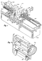
- Fig. 1 is a perspective view of the apparatus for automatically applying connectors to multiconductor flat cable according to the present invention;
- Fig. 2 is a perspective view of the parts of a multicontact connector of the general type which is assembled to multiconductor flat cable by the apparatus of Fig. 1;
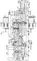
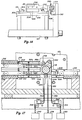
- Fig. 3 is a front elevation of a major portion of the apparatus shown in Fig. 1 with some parts broken away and other parts shown in section view taken along the line 3-3 in Fig. 7;
- Fig. 4 is a section view taken from the line 4-4 of Fig. 3;
- Fig. 5 is a section view taken from the line 5-5 of Fig. 3;
- Fig. 6 is a section view taken from the line 6-6 of Fig. 3;
- Fig. 7 is a section view taken from the line 7-7 of Fig. 3;
- Fig. 8 is a section view taken from the line 8-8 of Fig. 3;
- Fig. 9 is a section view taken from the line 9-9 of Fig. 8;
- Fig. 10 is a view taken from the line 10-10 of Fig. 7;
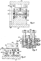
- Fig. 11 is a side elevation in section of the connector holding member and actuating mechanism therefor;
- Fig. 12 is a section view taken from the line 12-12 of Fig. 11;
- Fig. 13 is a section view taken from the line 13-13 of Fig. 11;
- Fig. 14 is a section view taken from the line 14-14 of Fig. 13;
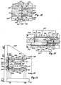
- Fig. 15 is a transverse side elevation of the apparatus partially sectioned and illustrating two of the connector magazine feed mechanisms;
- Fig. 16 is a transverse side elevation of the opposite end of the apparatus;
- Fig. 17 is a view taken from the line 17-17 of Fig. 7 and illustrating the magazine feed mechanism;
- Fig. 18 is a fragmentary view taken from the line 18-18 of Fig. 7; and
- Fig. 19 is a view taken from the line 19-19 in Fig. 15.
- The apparatus of the present invention is adapted to apply a connector of the general type shown in Fig. 2 to multi conductor flat cable also shown in Fig. 2 and generally designated by the
numeral 24. The connector shown in Fig. 2 includes abody part 26 on which are mounted a plurality of closely spacedinsulation displacement terminals 27. The connector shown in Fig. 2 also includes acover part 28 having elongated slots, not shown, for receiving the ends of theterminals 27. Thecover 28 is also provided withclips 30 disposed at the bottom ofrespective grooves 31 at opposite ends of the cover. Theclips 30 are operable to project intocooperative grooves 32 in the ends of thebody 26 to align and hold the body and cover parts in assembly. One side of thecover 28 includes an elongated shallow recess 34 into which the cable may be folded and held against the top of the cover by a strain relief member 36. The strain relief member 36 includes a pair ofdeflectable arms 37 which are adapted to hold the strain relief member in assembly with the other parts of the connector with the cable clamped therebetween in a known way. The general type of connector shown in Fig. 2 is well known and various specific types are known which differ in certain detailed respects. The specific type of connector shown in Fig. 2 is one of the Scotchflex brand connectors manufactured by the Minnesota Mining and Manufacturing Company, St. Paul, Minnesota. - Referring to Fig. 1 an overall perspective view of the apparatus is shown to facilitate an understanding of the arrangement of the major components. The apparatus of the present invention, generally designated by the
numeral 40, includes a frame 42 (see Fig. 3 also) which is shown mounted on a cabinet 44 which may house some of the control circuitry for operating the apparatus. Theframe 42 is adapted to support acable feeding unit 46 which is characterized by a pair of motor drivenrollers flat cable 24 which may be supplied to theapparatus 40 from a source such as a relatively large roll or the like, not shown. - The
apparatus 40 also includes spaced apart cable clamp and transfer units designated generally by thenumerals transfer units - The
frame 42 also supportselongated magazines numeral 58. Themagazines frame 42 also supports amagazine 60 disposed above themagazine 54 for holding a plurality of connector bodies side by side. - The
connector holding shaft 58, partially shown in Fig. 1, is operable to be moved from the position shown wherein connector body and cover parts may be inserted in the shaft to a position wherein theshaft 58 is interposed in the path of thecable 24 and the connector parts may be applied to the cable. Theframe 42 includes abridge portion 62 which includesvertical support plates actuator 64 for loading the connector bodies into theshaft 58 and anactuator 66 for pressing the connector bodies into assembly with a portion of the cable. Thebridge portion 62 also supports anactuator 68 which is operable to eject finished cable assemblies from theapparatus 40. - In Fig. 3 the
cable feed unit 46 is shown in section view taken from the centerline of the cable feed path. Referring to Figs. 3 and 4, therollers supports rollers respective gears roller 50 is directly connected to anelectric motor 78 which is desirably one which is responsive to rotate a predetermined amount when energized by a pulse type electrical signal and is precisely braked when deenergized. Such motors are commonly known as stepping motors. The bearings supporting theroller 48 are mounted on ashaft 80 which is disposed inblocks brackets roller 48 toward theroller 50 to forcibly engage thecable 24 disposed between the rollers. Accordingly, when therollers cable 24 is fed therebetween a linear amount proportional to the angular rotation of the rollers. Thecable feed unit 46 also includescable guides transverse supports 90 and 92 and on opposite sides of therollers guides 86, in Fig. 3. Theguides supports 90 and 92 and may be adjusted relative to each other laterally to accommodate different cable widths. - Referring to Figs. 3 and 5 the cable clamp and
transfer unit 51 is shown in further detail. Thecable clamp unit 51 includes asupport member 94 which is mounted on a pair of spaced apartcylindrical rails linear bearings 100. Therails member 90 and abase member 99 for a cable cutting mechanism to be described further herein. Thesupport 94 is connected to a pressure fluidcylinder type actuator 102 which is mounted under thetransverse members 90 and 92 of the cable feed unit. Anextensible piston rod 104 of theactuator 102 is suitably connected at its distal end to clampunit 51. Theclamp unit 51 includes a movablecable clamping jaw 106 which is connected to the piston rod of apressure fluid actuator 108 mounted on top of a supportingbridge 110. Theactuator 108 is operable to releasably clamp the cable between thejaw 106 and asurface 112 on thesupport 94. Theactuator 102 is operable to move thecable clamp unit 51 from the position shown in Fig. 3 toward theconnector holding shaft 58 to precisely position the leading edge of the cable in the holding shaft for application of a connector to the cable. - The
apparatus 40 also includes the aforementioned cable cutting mechanism which is shown in Fig. 3 and 6. The cable cutting mechanism includes thebase member 99 upon which is removable mounted ananvil support plate 114 which supports ananvil 116. Thesupport plate 114 is adapted to support spaced apart cable guides 118 and 120 in one of a plurality of selected positions depending on the width of the cable. The cable guides 118 and 120 are similar to theguides cable feed unit 46. A pressure fluidcylinder type actuator 122, mounted on thebridge 62, is operable to extend and retract apiston rod 124 connected to a cablecutting blade holder 126 in which is mounted acutting blade 128. Theblade holder 126 is guided for reciprocating movement by spaced apart guidepins 127 mounted on thebase 99, and the blade holder is biased into the retracted positon bycoil springs 129 disposed around thepins 127. - The
actuator 122 is operable to extend theholder 126 to cause theblade 128 to cut a length ofcable 24 disposed between theguides 118 and 120. - The cable clamp and
transfer unit 52 is disposed beyond the holdingshaft 58 in the direction of movement of a length ofcable 24 as it is prepared by the apparatus. Referring to Figs. 3 and 8, theclamp unit 52 includes ahousing 130 which is slidably supported on spaced apart rails 132 and 134 mounted on theframe 42. Thehousing 130 is connected to thepiston rod 136 of a doubleacting cylinder actuator 138 which is mounted on theframe 42, as shown in Fig. 3. Referring also to Fig. 9 thecable clamp unit 52 is further characterized by double acting cylinder actuator means comprising cylinder bores 140, 142, and 144.Pistons respective bores upper clamp jaw 150. A piston 152 is disposed in the bore 142 and is connected to alower clamp jaw 154. - In the position shown in Fig. 3 the
piston rod 136 is extended to position theclamp unit 52 adjacent to the holdingshaft 58 for receiving the trailing end portion of a length of cable. Thejaws shaft 58. Theclamp unit 52 is operable to clamp the cable after the leading end of the cable has been moved to the right, viewing Fig. 3, to establish the predetermined length of cable, and prior to cutting the cable to form the trailing end. Anadjustable stop 156 is mounted on thehousing 130 and is engageable with abumper 158 mounted on theframe 42. Aplate 160 fastened to thehousing 130 is provided for supporting the cable as it is fed past theclamp unit 52 and onto a secondcable supporting plate 162. - Referring to Figs. 3 and 7, the
connector holding shaft 58 is mounted in ahousing 166 fastened to thebridge member 63. The holdingshaft 58 includes anelongated slot 170 formed through the central axis of the shaft and opening to the distal end thereof. Theslot 170 is formed perpendicular to two alignedslots slot 170. Theslots connector body 26 andcover 28, respectively. The connector body and cover holding means will be explained in further detail herein. - The holding
shaft 58 is operable to move between the position shown by the solid lines in Fig. 7 and a position illustrated by the dashed lines in Fig. 7. Referring also to Fig. 10, when the holdingshaft 58 is in the position shown by the solid lines in Fig. 7 theslot 172 is aligned with arecess 176 formed in themagazine 60 which permits aram 178 connected to theactuator 64 to push aconnector body 26 into the slot. The connector body which is in position to be loaded into the holdingshaft 58 is urged by mechanism to be described against astop 177 while it is still in themagazine 60. Theslot 174 is also aligned with an opening between themagazines connector cover 28 from one or the other of the magazines. As shown in Fig. 7, theram 178 is guided for reciprocating movement in a vertical plane by spaced apart guiderods 182. A similarretractable ram 184 is disposed below themagazines ram 178 byguide rods 186. Theram 184, which is particularly adapted to engage and hold aconnector cover 28 of the type shown in Fig. 2, includes spaced apart upwardly extendingprojections 187 which are operable to extend into thegrooves 31 of the opposite ends of the covers for maintaining proper alignment of the cover. Theram 184 is connected to a pressure fluidcylinder type actuator 188. - When a connector body and cover member have been loaded into the holding
shaft 58, the shaft is actuated to be extended to the dashed line position shown in Fig. 7. In the extended position of the holdingshaft 58 thecable 24 normally extends into or through theslot 170. Theslots opposed rams ram 190 is connected to thecylinder actuator 66 and is guided by spaced apart guiderods 194 for reversible linear movement in a vertical plane. Theram 192 is also connected to acylinder actuator 196 mounted under theframe 42 and is guided for reversible linear movement byrods 198. Theram 192 as well as theram 190 may be formed to have interchangeable members havingrespective recesses apparatus 40. - When the holding
shaft 58 is moved to the position shown by the dashed lines in Fig. 7 and the cable is disposed in theslot 170 theram 192 is actuated to move upward, viewing Fig. 7, to engage aconnector cover 28 disposed in theslot 174 and move the cover into position directly under and engageable by thecable 24. Theram 190 is then actuated to move downward, viewing Fig. 7, to engage and press aconnector body 26 into engagement with thecable 24 and theclips 30 of the connector cover to assemble the connector to the cable. When the connector is applied to the cable theshaft 58 is retracted to the position represented by the solid lines of Fig. 7 and therams feed mechanism 46 or is ejected by theactuator 68 if the operation involved applying a connector to the trailing end of the cable. - For application of connectors of the type shown in Fig. 2 to the cable ends, it is necessary that the
covers 28 be arranged so that the recess 34 is facing in a direction to receive the cable when the cable is folded over the top of the cover prior to application of the strain relief member 36. Accordingly, thecovers 28 must be loaded into one or the other of themagazines magazines - Selection of a
cover 28 from themagazine shaft 58 is provided by mechanism shown in Figs. 10 and 18. As shown in Fig. 18, two spaced apart supportfingers 204 are mounted on amagazine support plate 206 and extend across the opening betweenmagazines shaft 58. Thecover loading ram 184, as shown in Fig. 7, haschannels fingers 204 when the ram is actuated to insert acover 28 into the holdingshaft 58. The magazine selector mechanism includes a gate characterized by an invertedU-shaped member 212, as shown also in Fig. 7, which extends across the end of themagazine 56 in the position shown in Fig. 18. Referring to Fig. 10, thegate 212 is connected to a pressure fluidcylinder type actuator 214 mounted under themagazine 54. Thepiston rod 218 of theactuator 214 is connected to anintermediate member 216 which is connected to thegate 212. Spaced apart guiderods 220, one shown in Fig. 10, extend from themember 216 into complementary bores in amounting block 222 for theactuator 214. Theactuator 214 is operable to move thegate 212 from the position shown in Fig. 10 blocking the feeding of cover parts from themagazine 56 to a position abutting the end ofmagazine 54 to block the feeding of cover parts from themagazines 54. A similar mechanism and second magazine could, of course, be provided and arranged in a similar way with respect to themagazine 60 for selection of the connector bodies, if desired. - Referring to Figs. 11 and 12, the
housing 166 includes aninterior bore 226 in which is disposed atubular sleeve 228 supported for rotation onbearings 230. The holdingshaft 58 is mounted in thesleeve 228 and is slidable with respect to the sleeve in opposite directions along the longitudinal coincident central axes of the shaft and sleeve. Thesleeve 228 includes two spaced apartkeys 232 which project into akey slot 234 formed in theshaft 58 whereby the shaft is longitudinally slidable but nonrotatable with respect to the sleeve. The end of theshaft 58 opposite that which includes theslot 170 is provided with anarm 236 connected to the piston rod 238 of a pressure fluid linear actuator formed by apiston 240 disposed for reciprocation in abore 242 in thehousing 166. Thearm 236 includes anadjustable stop 244 engageable with thehousing 166 for adjustment of the extended position of theshaft 58 shown by the dashed lines in Fig. 7. Acollar 246 mounted on the end of theshaft 58 is adapted to engage spaced apartelectrical switches bracket 252 fastened to thehousing 166. - As shown in Fig. 12, the
sleeve 228 includes an integrally formedgear portion 254 which is meshed with agear rack 256 disposed for linear reciprocating movement in thehousing 166 in directions perpendicular to the longitudinal axis of theshaft 58. Anarm 258 connected to one end of therack 256 is also connected to thepiston rod 260 of a pressure fluidcylinder type actuator 262 mounted on thehousing 166. Theactuator 262 is operable to drive therack 256 in opposite directions to reversibly rotate thesleeve 228 andshaft 58. Anadjustable stop 264 is mounted on thearm 258 for limiting the rotary position of theshaft 58 in one direction of rotation. Acollar 266 mounted on therack 256 is operable to engage a pair of spaced apart switches 268amd 270, as shown in Fig. 11. - Referring to Figs. 13 and 14, the
slots part gripping jaws jaws 272 are detachably secured to theshaft 58 byfasteners 276. As shown by way of example in Fig. 14 thejaws 274 are retained on theshaft 58 bysuitable fasteners 278 and are biased toward thejaws 272 bysprings 280 interposed between thejaws 274 and a side wall of theslots jaws 274 may be yieldably biased into engagement with the connector cover and body parts, respectively, to hold the parts in theshaft 58 until the connector is applied to the cable and the shaft is retracted away from the cable. - Fig. 15 illustrates a transverse elevation of the
magazines magazine 60 comprises anelongated tray 288 including spaced apart guides 290 adapted to retain a plurality ofconnector bodies 26 on the magazine side by side. Themagazine 60 is removably supported on theapparatus 40 by structure comprising spaced apartsupport members magazine 60 is thus slidably supported by therails 296 for removal from the apparatus when empty or when a replacement magazine is to be placed on theapparatus 40. Themagazine 54 is also characterized by anelongated tray 297 which is removably disposed on asupport plate 298 mounted on theframe 42 and also including spaced apart magazine retaining rails 300. Thetray 297 is adapted to support a plurality of connector covers 28 side by side and retained on the magazine by spaced apart guides 302. - Referring to Fig. 16 also, the second
connector cover magazine 56, disposed opposite themagazine 54, is also removably supported on theplate 206 mounted on theframe 42. Themagazine 56 also includes anelongated tray 304 adapted to support a plurality of connector covers 28 side by side between spaced apart guides 306. Thetray 304 is disposed between oppositely facing guide rails 308. As shown in Fig. 10, thetray 304 includes arecess 305 which provides clearance for the connectorcover support fingers 204. The top surfaces of thefingers 204 are even with the top surface of thetray 304. - Referring again to Fig. 15 and Fig. 19, the
magazines movable pusher plates shaft 58 for subsequent loading thereinto. Thepusher plate 312 is connected to a bracket assembly 376 by means of a springbiased hinge 317 so that the plate may be moved clear of themagazine 54 to permit loading and unloading of themagazine tray 297 with respect to theapparatus 40. Thebracket 316 has mounted thereon spaced apartcylindrical rollers 318 which are each provided with a circumferential recess to provide for retaining the rollers between spaced apart tracks 320 mounted on theapparatus 40. Thetracks 320 extend parallel to themagazines pusher plate 312 substantially the full length of themagazine 54. - The
pusher plate 314 is similarly mounted onhinge 317 which is connected to abracket 322. Thebracket 322 is guided for movement along themagazine 60 by a pair ofrollers 318 mounted on the bracket and engaged with a second set oftracks 320 mounted above the tracks which guide thepusher plate 312. - Referring to Fig. 16 the
magazine 56 is also provided with a hingedpusher plate 326 for moving the connector covers toward the holdingshaft 58. Thepusher plate 326 is mounted on abracket 328 similar to thebrackets parallel tracks 330. - The
pushes plates respective magazines bracket 312 is shown connected to aflexible cable 332 which is trained over asheave 334 mounted on thevertical support plate 63. The opposite end of thecable 332 is connected to a hangingweight 336. In like manner thebrackets flexible cables cable 340 is connected to aweight 342 and is trained over a sheave mounted next to sheave 334, not shown, andsheaves 344 and 346 to provide for spacing theweight 342 from theweight 336. Thecable 338 is similarly trained oversheaves weights - The
apparatus 40 may be operated in a preferred mode by a suitable electrical control system comprising electrical proximity or limit switches, some of which are illustrated in the drawings, together with time delay devices and logic devices which are operable to actuate solenoid valves for supplying pressure fluid to the various actuators included in the apparatus in a predetermined sequence. Such a control system also would preferably include a control circuit for energizing themotor 78 of thecable feed unit 46 to feed a predetermined amount of cable through the apparatus. - An operating cycle of the apparatus will now be described assuming that a cable assembly has previously been prepared and the apparatus is ready for another operating cycle. Prior to commencement of an operating cycle the leading edge of the cable would be positioned at the cut line of the
cutting blade 128. Thecable cutting blade 128 and theclamp units rams connector holding shaft 58 would be in the position shown by the solid lines in Fig. 7. - An operating cycle would commence with energization of the
actuators respective rams slots shaft 58. Therams bore 242 to causepiston 240 to move theshaft 58 to the position represented by the dashed lines in Fig. 7. Simultaneously, with the energization of the holding shaft actuator thecable clamp 106 is actuated to clamp the cable. After the holdingshaft 58 is moved into position to receive the cable which is signalled by actuation of theswitch 248, Fig. 11, thecylinder actuator 102 is actuated to move theclamp unit 51 to the right, viewing Fig. 3, from the position shown so that the leading end of the cable is inserted into the holdingshaft slot 170 between the connector cover andbody parts - When the cable is positioned in the holding
shaft 58 theactuator 196 is energized to move theram 192 upward to move the connector cover up to the cable and provide support for the cover. Theactuator 66 is then sequentially energized to cause theram 190 to press the connector body into engagement with the cable and the connector cover to complete the assembly process. - After a connector is applied to the leading edge of the cable the holding shaft linear movement actuator is caused to retract the holding
shaft 58 to the position shown by the solid lines in Fig. 7. Therams clamp jaw 106 are also subsequently retracted after a short time delay. Thefeed motor 78 is then energized by a predetermined repeating pulse signal which varies in accordance with the length of cable to be fed to thereby cause thefeed unit 46 to feed a predetermined length of cable past thecutting blade 128. During the cable feed process theactuator 102 returns theclamp unit 51 to the position shown in Fig. 3 and theactuator 214 moves thegate 212 so that a connector cover having its recess turned opposite to that of the cover previously applied may be positioned for loading into the holdingshaft 58. If a connector is to be applied intermediate the ends of the length of cable being prepared or if connector covers without special nonsymmetric configuration were being used, actuation of the gate would not be necessary until one of the magazines was empty. After movement of thegate 212, as the case may be, therams shaft 58. When the cable is fed out a predetermined amount, thecable clamp unit 52 is actuated to causejaws shaft 58 is then subsequently moved into the connector application position. When theshaft 58 is in position with the cable inserted in theslot 170 theactuator 122 is energized to cut the cable and then deenergized to cause thecutting blade 128 to retract to the noncutting position. - When the
cutting blade 128 is retracted a limit switch is actuated which provides for operation of theactuator 138 to move theclamp unit 52 to the right, viewing Fig. 3, to place the trailing end of the cable in position for application of the connector thereto. Movement of theclamp unit 52 to the limit position will actuate a suitable limit switch, not shown, which causes sequential actuation of therams shaft 58 is then retracted and theclamp jaws - When the holding
shaft 58 is retracted to engage theswitch 250, Fig. 11, suitable solenoid valves are actuated to cause therams gate 212 back to its initial position. Simultaneously, theactuator 68 is energized to eject a completed cable assembly toward the front of the apparatus for removal therefrom. After a suitable time delay theactuator 138 is energized to return theclamp unit 52 to the position shown in Fig. 3. When theclamp unit 52 reaches its starting position, a suitable light switch, not shown, is actuated to condition the control circuit for another operating cycle. - In the application of a connector to a cable at either end of the length of cable or at some intermediate point between the cable ends, it is sometimes desired to invert the connector with respect to the cable as well as the other connector or connectors applied to the cable. If inversion of the connector was desired, the control circuit would cause the
actuator 262, Fig. 12, to rotate the holdingshaft 58 after the connector parts were loaded into theslots shaft 58 would then be extended to the dashed line position shown in Fig. 7 and the operating cycle would proceed as previously described. Upon retraction of the holdingshaft 58, after completion of a connector application, the actuator 262.would be reversed to rotate the holding shaft back to its original rotative position preparatory to receiving another connector.
Claims (21)
Priority Applications (1)
| Application Number | Priority Date | Filing Date | Title |
|---|---|---|---|
| AT80103226T ATE4619T1 (en) | 1979-06-18 | 1980-06-11 | DEVICE FOR ATTACHING CONNECTORS TO A MULTI-WIRE FLAT CABLE. |
Applications Claiming Priority (2)
| Application Number | Priority Date | Filing Date | Title |
|---|---|---|---|
| US06/049,842 US4281442A (en) | 1979-06-18 | 1979-06-18 | Apparatus for applying connectors to multiconductor flat cable |
| US49842 | 1979-06-18 |
Publications (2)
| Publication Number | Publication Date |
|---|---|
| EP0021237A1 EP0021237A1 (en) | 1981-01-07 |
| EP0021237B1 true EP0021237B1 (en) | 1983-09-07 |
Family
ID=21962034
Family Applications (1)
| Application Number | Title | Priority Date | Filing Date |
|---|---|---|---|
| EP80103226A Expired EP0021237B1 (en) | 1979-06-18 | 1980-06-11 | Apparatus for applying connectors to multiconductor flat cable |
Country Status (5)
| Country | Link |
|---|---|
| US (1) | US4281442A (en) |
| EP (1) | EP0021237B1 (en) |
| JP (1) | JPS587033B2 (en) |
| AT (1) | ATE4619T1 (en) |
| DE (1) | DE3064747D1 (en) |
Families Citing this family (36)
| Publication number | Priority date | Publication date | Assignee | Title |
|---|---|---|---|---|
| US4370806A (en) * | 1979-02-16 | 1983-02-01 | Molex Incorporated | Electrical harness fabrication apparatus |
| US4310967A (en) * | 1979-02-16 | 1982-01-19 | Molex Incorporated | Apparatus for electrical harness fabrication |
| US4344225A (en) * | 1980-02-25 | 1982-08-17 | Amp Incorporated | Pre-assembly and terminating apparatus |
| US4332083A (en) * | 1980-05-15 | 1982-06-01 | Amp Incorporated | Terminating apparatus for flat cable |
| US4439919A (en) * | 1980-11-14 | 1984-04-03 | Burndy Corporation | Automatic lead making apparatus |
| US4345963A (en) * | 1981-06-01 | 1982-08-24 | Abbott Laboratories | Assembly machine for I.V. components |
| US4630362A (en) * | 1981-10-26 | 1986-12-23 | Burndy Corporation | Apparatus for installing electrical on flat conductor cable |
| JPS58123686A (en) * | 1982-01-19 | 1983-07-22 | 日本圧着端子製造株式会社 | Both end pressing machine for pressure contact connector |
| NL8200252A (en) * | 1982-01-25 | 1983-08-16 | Markert Heinrich Willy | METHOD AND APPARATUS FOR CUTTING GENDER ANIMALS IN PARTS |
| US4429455A (en) | 1982-02-03 | 1984-02-07 | Minnesota Mining And Manufacturing Company | Connector application machine |
| FR2521358A1 (en) * | 1982-02-10 | 1983-08-12 | Amp France | METHOD AND APPARATUS FOR COUPLING AN INSULATING CONNECTOR HOUSING AND A COVER FOR THIS HOUSING TO PROVIDE A TERMINATION ON AN ELECTRICAL CONDUCTOR |
| US4641427A (en) * | 1982-02-23 | 1987-02-10 | Shields Charles E | Method and apparatus for applying two piece connector blocks to multiconductor cable |
| US4580340A (en) * | 1982-02-23 | 1986-04-08 | Shields Charles E | Method and apparatus for applying two piece connector blocks to multiconductor cable |
| ATE17620T1 (en) * | 1982-07-02 | 1986-02-15 | Amp Inc | DEVICE AND METHOD FOR ATTACHING TERMINALS TO FLAT FLEXIBLE CABLES. |
| JPS5914283A (en) * | 1982-07-15 | 1984-01-25 | 株式会社東京精研社 | Pressure contact coupling device for connector |
| US4486949A (en) * | 1982-09-30 | 1984-12-11 | Burndy Corporation | Apparatus and process for installing IDC connectors onto a ribbon cable |
| US4481710A (en) * | 1982-10-28 | 1984-11-13 | Panduit Corp. | Tool for applying connectors |
| JPS59108286A (en) * | 1982-12-10 | 1984-06-22 | 富士通株式会社 | Connector pressure contacting device |
| GB2134422B (en) * | 1983-02-01 | 1985-11-13 | Amp Inc | Apparatus for terminating an electrical conductor to an electrical connector |
| US4561155A (en) * | 1983-06-22 | 1985-12-31 | Artos Engineering Company | Cord manufacturing apparatus and connector attachment machine therefor |
| US4566164A (en) * | 1985-02-08 | 1986-01-28 | Amp Incorporated | Apparatus for connecting electrical connectors to flat multi-conductor cable |
| US4580867A (en) * | 1985-02-12 | 1986-04-08 | Molex Incorporated | Method and apparatus for terminating a reciprocable connector |
| US4852248A (en) * | 1985-02-19 | 1989-08-01 | Burndy Corporation | Connector installation station for compact semi-automatic cable assembly system |
| US4761879A (en) * | 1985-02-19 | 1988-08-09 | Burndy Corporation | Connector installation station for compact semi-automatic cable assembly system |
| US4607554A (en) * | 1985-02-25 | 1986-08-26 | Amp Incorporated | Cable severing station |
| US4563810A (en) * | 1985-02-25 | 1986-01-14 | Amp Incorporated | Electrical connector transfer nest |
| US4584757A (en) * | 1985-02-25 | 1986-04-29 | Amp Incorporated | Assembly for connecting electrical connectors to flat multiconductor cable |
| US4682391A (en) * | 1985-08-21 | 1987-07-28 | Amp Incorporated | Cable harness assembly apparatus |
| FR2597290B1 (en) * | 1986-04-14 | 1990-06-15 | Amp France | METHOD AND APPARATUS FOR MANUFACTURING CONDUCTOR BEAMS |
| JPH0465180U (en) * | 1990-10-12 | 1992-06-05 | ||
| US5074038A (en) * | 1991-01-25 | 1991-12-24 | Amp Incorporated | Cable making machine and method of manufacture |
| US5537735A (en) * | 1995-01-03 | 1996-07-23 | The Whitaker Corporation | Separating, terminating, assembling tool for electrical connector |
| JP3395550B2 (en) * | 1996-11-22 | 2003-04-14 | 矢崎総業株式会社 | Pressure welding apparatus and harness manufacturing method |
| JP3783541B2 (en) * | 2000-09-11 | 2006-06-07 | 住友電装株式会社 | Pressure welding joint connector connection device |
| DE50208308D1 (en) * | 2001-05-07 | 2006-11-16 | Komax Holding Ag | Device for assembling flexible printed circuit boards |
| CN111071701A (en) * | 2019-12-30 | 2020-04-28 | 季华实验室 | Connector automatic feeding device |
Family Cites Families (15)
| Publication number | Priority date | Publication date | Assignee | Title |
|---|---|---|---|---|
| US2281478A (en) * | 1939-08-31 | 1942-04-28 | Chirelstein Nathan | Assembling machine |
| US2357693A (en) * | 1942-05-02 | 1944-09-05 | Western Electric Co | Assembling apparatus |
| US3284885A (en) * | 1963-11-15 | 1966-11-15 | Itt | Tool for crimping termination elements to flat electrical cables |
| FR1599370A (en) * | 1968-12-20 | 1970-07-15 | ||
| US3861018A (en) * | 1974-01-10 | 1975-01-21 | Nippon Acchakutanahi Seizo Kab | Apparatus for attachment of a connector to an end of a wire |
| US3956811A (en) * | 1974-04-30 | 1976-05-18 | Elco Corporation | Apparatus for terminating flat conductor cable |
| JPS5290082A (en) * | 1976-01-13 | 1977-07-28 | Amp Inc | Apparatus for engaging first and second portions of electric connector |
| US4043017A (en) * | 1976-02-11 | 1977-08-23 | Amp Incorporated | Apparatus for inserting wires into terminals and for manufacturing electrical harnesses |
| US4020540A (en) * | 1976-02-26 | 1977-05-03 | Amp Incorporated | Applicator tool |
| US4110880A (en) * | 1977-02-25 | 1978-09-05 | Amp Incorporated | Cable harness assembly and electrical testing machine |
| US4126935A (en) * | 1977-05-31 | 1978-11-28 | Bell Telephone Laboratories, Incorporated | Method and apparatus for manufacturing wiring harnesses |
| US4136440A (en) * | 1977-07-12 | 1979-01-30 | Amp Incorporated | Electrical harness fabrication method and apparatus |
| US4148130A (en) * | 1977-12-06 | 1979-04-10 | Amp Incorporated | Cable harness assembly apparatus |
| US4174560A (en) * | 1978-03-17 | 1979-11-20 | Cooper Industries, Inc. | Tool for applying connectors to flexible cable |
| US4159565A (en) * | 1978-05-08 | 1979-07-03 | Amp Incorporated | Cover and strain relief applicator apparatus |
-
1979
- 1979-06-18 US US06/049,842 patent/US4281442A/en not_active Expired - Lifetime
-
1980
- 1980-06-11 DE DE8080103226T patent/DE3064747D1/en not_active Expired
- 1980-06-11 AT AT80103226T patent/ATE4619T1/en not_active IP Right Cessation
- 1980-06-11 EP EP80103226A patent/EP0021237B1/en not_active Expired
- 1980-06-18 JP JP55082699A patent/JPS587033B2/en not_active Expired
Also Published As
| Publication number | Publication date |
|---|---|
| ATE4619T1 (en) | 1983-09-15 |
| JPS587033B2 (en) | 1983-02-08 |
| JPS563985A (en) | 1981-01-16 |
| DE3064747D1 (en) | 1983-10-13 |
| EP0021237A1 (en) | 1981-01-07 |
| US4281442A (en) | 1981-08-04 |
Similar Documents
| Publication | Publication Date | Title |
|---|---|---|
| EP0021237B1 (en) | Apparatus for applying connectors to multiconductor flat cable | |
| US3872584A (en) | Method and apparatus for processing a plurality of wire leads | |
| US4296881A (en) | Surgical stapler using cartridge | |
| EP0286206B1 (en) | Electrical-terminal block loading apparatus | |
| JPS5940583B2 (en) | Machine tool with adjustable device for fixing and displacing the workpiece relative to the tool | |
| US4753099A (en) | Bending press for sheet metal | |
| US4566164A (en) | Apparatus for connecting electrical connectors to flat multi-conductor cable | |
| JP3221544B2 (en) | Crimping machine assembly, terminal crimping unit and automatic terminal crimping device | |
| DE3686450T2 (en) | DEVICE FOR PRODUCING ELECTRICAL WIRING HARNESSES. | |
| US4344225A (en) | Pre-assembly and terminating apparatus | |
| EP0119599B1 (en) | Forming apparatus for performing bending operations | |
| US3796363A (en) | Multiple component insertion apparatus | |
| US4682391A (en) | Cable harness assembly apparatus | |
| US4683636A (en) | Wire preparation system | |
| EP0001891A1 (en) | Apparatus for inserting wires into electrical terminals | |
| US4253222A (en) | Apparatus for applying assembled connector terminals to a plurality of leads | |
| US4623293A (en) | Apparatus for orientating elongate bodies | |
| US4270267A (en) | Machine for mass insertion of electrical terminals | |
| SU1134266A1 (en) | Device for cutting wire to length | |
| US5842266A (en) | Apparatus for producing wire harnesses | |
| EP0001678B1 (en) | Wire deploying apparatus | |
| US5147080A (en) | Staple forming and stapling machine | |
| EP0171993A2 (en) | Improvements in or relating to apparatus for assembling two-part connectors | |
| EP0801826A1 (en) | Apparatus for producing wire harnesses | |
| JP2772313B2 (en) | Connector moving mechanism of wire pressure welding device |
Legal Events
| Date | Code | Title | Description |
|---|---|---|---|
| PUAI | Public reference made under article 153(3) epc to a published international application that has entered the european phase |
Free format text: ORIGINAL CODE: 0009012 |
|
| AK | Designated contracting states |
Designated state(s): AT DE FR GB IT SE |
|
| 17P | Request for examination filed |
Effective date: 19810328 |
|
| ITF | It: translation for a ep patent filed | ||
| GRAA | (expected) grant |
Free format text: ORIGINAL CODE: 0009210 |
|
| AK | Designated contracting states |
Designated state(s): AT DE FR GB IT SE |
|
| RAP1 | Party data changed (applicant data changed or rights of an application transferred) |
Owner name: COOPER INDUSTRIES INC. |
|
| REF | Corresponds to: |
Ref document number: 4619 Country of ref document: AT Date of ref document: 19830915 Kind code of ref document: T |
|
| REF | Corresponds to: |
Ref document number: 3064747 Country of ref document: DE Date of ref document: 19831013 |
|
| ET | Fr: translation filed | ||
| PG25 | Lapsed in a contracting state [announced via postgrant information from national office to epo] |
Ref country code: AT Effective date: 19840611 |
|
| PG25 | Lapsed in a contracting state [announced via postgrant information from national office to epo] |
Ref country code: SE Effective date: 19840612 |
|
| PLBE | No opposition filed within time limit |
Free format text: ORIGINAL CODE: 0009261 |
|
| STAA | Information on the status of an ep patent application or granted ep patent |
Free format text: STATUS: NO OPPOSITION FILED WITHIN TIME LIMIT |
|
| 26N | No opposition filed | ||
| GBPC | Gb: european patent ceased through non-payment of renewal fee | ||
| PG25 | Lapsed in a contracting state [announced via postgrant information from national office to epo] |
Ref country code: FR Free format text: LAPSE BECAUSE OF NON-PAYMENT OF DUE FEES Effective date: 19850228 |
|
| PG25 | Lapsed in a contracting state [announced via postgrant information from national office to epo] |
Ref country code: DE Effective date: 19850301 |
|
| REG | Reference to a national code |
Ref country code: FR Ref legal event code: ST |
|
| PG25 | Lapsed in a contracting state [announced via postgrant information from national office to epo] |
Ref country code: GB Effective date: 19881118 |
|
| EUG | Se: european patent has lapsed |
Ref document number: 80103226.9 Effective date: 19850612 |