EP0020845A1 - Plasmabrenner - Google Patents
Plasmabrenner Download PDFInfo
- Publication number
- EP0020845A1 EP0020845A1 EP79850055A EP79850055A EP0020845A1 EP 0020845 A1 EP0020845 A1 EP 0020845A1 EP 79850055 A EP79850055 A EP 79850055A EP 79850055 A EP79850055 A EP 79850055A EP 0020845 A1 EP0020845 A1 EP 0020845A1
- Authority
- EP
- European Patent Office
- Prior art keywords
- electrode
- electrodes
- burner according
- burner
- holder
- Prior art date
- Legal status (The legal status is an assumption and is not a legal conclusion. Google has not performed a legal analysis and makes no representation as to the accuracy of the status listed.)
- Granted
Links
Images

Classifications
-
- B—PERFORMING OPERATIONS; TRANSPORTING
- B23—MACHINE TOOLS; METAL-WORKING NOT OTHERWISE PROVIDED FOR
- B23K—SOLDERING OR UNSOLDERING; WELDING; CLADDING OR PLATING BY SOLDERING OR WELDING; CUTTING BY APPLYING HEAT LOCALLY, e.g. FLAME CUTTING; WORKING BY LASER BEAM
- B23K10/00—Welding or cutting by means of a plasma
-
- H—ELECTRICITY
- H05—ELECTRIC TECHNIQUES NOT OTHERWISE PROVIDED FOR
- H05B—ELECTRIC HEATING; ELECTRIC LIGHT SOURCES NOT OTHERWISE PROVIDED FOR; CIRCUIT ARRANGEMENTS FOR ELECTRIC LIGHT SOURCES, IN GENERAL
- H05B7/00—Heating by electric discharge
-
- H—ELECTRICITY
- H05—ELECTRIC TECHNIQUES NOT OTHERWISE PROVIDED FOR
- H05B—ELECTRIC HEATING; ELECTRIC LIGHT SOURCES NOT OTHERWISE PROVIDED FOR; CIRCUIT ARRANGEMENTS FOR ELECTRIC LIGHT SOURCES, IN GENERAL
- H05B7/00—Heating by electric discharge
- H05B7/02—Details
- H05B7/06—Electrodes
Definitions
- constructors have not been able to place the plasma burner in contact with the medium which is to be heated.
- constructor has chosen to place the plasma burner far from the object which is to be heated, this involves a loss of energy in the transfer of heat from the plasma flame.
- the main object of the invention is to create a plasma burner which can be used under conditions where hitherto it has not been technically possible to employ known plasma burners by virtue of their construction and the materials which they are made of.
- the plasma burner according to the invention must be able to burn with the electrodes and the plasma flame submerged in a melt.
- each of the electrodes are further adapted so that the eating away of the electrodes caused by the development of heat in the electric arc occurs at the same speed in the axial direction for both the electrodes, so that the electrical and gas-dynamic operational conditions and with this the heating effect and the blowing effect (the impulse) of the outwardly flowing gas is not altered substantially as a consequence of the comsumption of the electrode.
- the coaxial electrodes are mounted in a suitable electrode holder with means for coupling electric current, supplying gas to the hollow space between the electrodes and usually also cooling water for cooling the electrode holder itself.
- the advantageous features of the electrode holder are recited in dependent claims 5-8.
- An advantageous property of the plasma burners of the invention is that the open end of the electrode system,where the electric arc burns, develops by itself a natural and stable form after a running-in period of short duration. Both the rod and pipe electrode can in practice, therefore, possibly be cut off straight at the start.
- the present invention also distinguishes itself on this point conclusively from known constructions, where the electrical and gas-dynamic conditions and with this the use properties for these are critically dependent upon the exact design of the electrodes as well as the other parts of the plasma burner.
- Plasma burners according to the invention can, in addition to chemically neutral gases such as argon, helium and nitrogen, also work with gases and gas mixtures which react chemically with the electrode material at high temperatures, for example air or hydrogen in combination with graphite electrodes, or which undergo chemical changes, if it is desired to obtain a special effect by using chemically active gases.
- chemical electrode degradation which follows from this, which comes in addition to the unavoidable eating away which is due to the electric arc itself, does not reduce the characteristic ability of the burner to function stably independently of the reducing electrode length.
- the gas can be added to finely divided solid or liquid material in order to obtain an intended chemical reaction with substances in the environment of the burner, the object being, for example, to remove contaminants from a metal melt (refining) or to reduce the melting point of a material which is to be melted by adding a flux.
- the plasma burner can very readily be ingnited by producing a short circuit of short duration by indroducing graphite felt, steel wool, a metal fibre or the like in the opening between the electrodes.
- graphite electrodes are, for example, not damaged by virtue of local melting of the surface as a consequence of the short circuit.
- the plasma burners according to the invention can also be started by lowering down into an electrically conducting melt, for example metal. It is thus not necessary to use expensive special equipment for igniting the burner.
- Such a metal pipe around the outer electrode will obviously also be able to reduce the eating away of the carbon from the outer side of the electrode as a consequence of oxidation of other chemical attack.
- the material of the electrodes of the plasma burner according to the invention will be able to react with the fluid which the electrodes are submerged in. If such electrodes made of graphite are lowered into liquid steel one will get in unfavourable cases an undesirable reaction between the graphite and the steel due to the carbon being dissolved in the melt. This type of dissolution reaction can be prevented or the speed of dissolution of the carbon from the outer electrode to the bath can be reduced to an acceptable level by covering the surface of the outer electrode with an oxidic fire-resistant material which is eaten away in step with the electrode.
- oxidic materials are known in the art under the proprietary names "Gun Clay”, “Gunmix”,”Uniguncast-S”, “Trimrecast”, "Durax 1600" or "H44".
- Oxygen blowing is effected most often by blowing oxygen through a thin iron or steel pipe which is inserted in the tap hole. Compared with the plasma burners according to the invention a red-hot and burning oxygen pipe gives poor control of dimensions and direction of the tap hole.
- a plasma burner according to the invention can be used for this purpose. Particularly in the transfer of heat to melts having a relatively high melt or softening temperature, the new plasma burners will be well suited.
- Gas burners are also employed, but these will have a relatively rapidly diminishing thermal efficiency at increasing temperatures of the melt when traditional fuels are used.
- the combination of heat-retention and blowing in of gas and solid particles with the described plasma burners will be able to provide conditions for chemical reactions between solid phase and melt phase, between gas/ melt phase or between melted phases mutually.
- the reason for this situation lies in the control of temperature and stirring conditions of the melt so that the chemical reactions go much more rapidly than in the conventional process.
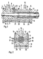
- a plasma burner has a rod electrode 1 composed of graphite and having a diameter of 30 mm fastened in a contact means A consisting of an upper contact member 2 and a lower contact member 3 which are screwed together by means of two pairs of threaded bolts 4.
- the recess in the upper (or lower) contact member is formed as a segment of a circle of 30 mm diameter and with a centre 1 mm below (or above) the under side of the contact member (or the upper side).
- the upper contact member 2 is provided with a contact rail 5 for coupling current cables, in this instance two parallel welding cables of standard type designed for 500 A.
- the electrically conducting connection between the upper and lower contact member was established via the bolts 4.
- the necessary gas (typically 25-250 Nl/min) for the operation of the plasma burner was led via a duct 8 through the upper contact member 2 into the annular shaped space 9 situated around the rod electrode, formed by the previously mentioned recesses in the contact members 2 and 3 being widened at the one end.
- the purpose of the space 9 is to obtain a more uniform distribution of the gas flow between the rod and pipe electrodes.
- the contact means (A) for the rod electrode is electrically insulated from the corresponding means (B) for the pipe electrode by means of an insulating plate 10 made of a suitable heat-durable insulation material, for example, "Syndanyo" of "Marinite". Between the rod electrode and the insulating plate is a relatively narrow, annular column, through which the gas with possible powder addition is able to pass.
- the powder can be supplied together with the gas through the duct 8 and transported pneumatically through the electrode holder and out between the electrodes.
- the outer electrode is a graphite pipe 11 having an inner diameter of 40 mm and an outer diameter of 60 mm.
- the contact means B for the pipe electrode is constructed according to the same principles as the afore-described contact means for the rod electrode, and thus consists of an upper contact member 12 and a lower contact member 13 joined together with two pairs of bolts 14. Further, the contact means is provided with a contact rail 15, cooling ducts 16 together with inlet and outlet pipes 17,18 for cooling water. The recesses of the contact members 12 and 13 are adapted to the outer diameter of the pipe electrode.
- the contact means A, B for the rod electrode 1 and the pipe electrode 11 respectively together with the intermediate insulating plate 10 are fastened by means of two pairs of screws 19 and 20 respectively, to a stable base plate 21 made of a mechanically solid insulating material.
- the holes in the plate for the screws 19 are made somewhat larger than these, so that the contact means A is able to be adjusted somewhat relative to the contact means B in order to obtain accurate centering of the electrodes.
- the plasma burner is to be used for a purpose which requires relatively long electrodes, and then especially on operating in a horizontal position, of where it is appropriate to work with relatively small radial electrode distances, it is advantageous with respect to centering to place a suitable number of short, relatively thin-walled pipe pieces 22 in between the electrodes about 10-20 cm from the openend(for example 20-21 pipes with outer diameters of 4.5-5 mm and lengths about 15 mm between a rod electrode with a diameter of 30 mm and a pipe electrode with an inner diameter of 40 mm.
- the excess pressure in the electrode holder must be at least as large as the hydrostatic pressure in the melt, for example, min. 0.7 bar at 1 m immersion in an iron melt.
- suitable packings can be disposed between the contact members 2 and 3 and 12 and 13 respectively, and between the insulating plate 10 and the contact means A and B. Further there can be employed an especially dense quality of graphite and if desired an especially thick material in the pipe electrode in order to reduce the gas diffusion through the pipe wall, if one does not desire gas generation from the electrode surface.
- a prototype for alternating current operation has the following dimensions and typical operational data: Current Source: two series coupled transformators max. current strength: ca. 1500 A no-load voltage 180 V
- the plasma burner is considered to be mounted in a stationary or mobile rig 31 constructed according to known principles, where the electrode holder can be moved up and down in a slide 33 by means of for example a spindle driven by a motor 34. In this way, the submerging H of the electrode system 35 in the metal melt 36 can be regulated.
- the inclination of the electrode system 35 can be adjusted by turning the slide 33 about the shaft 37 by means of, for example, a hydraulic cylinder 38.
- the plasma burner 41 is considered mounted on a constructed rig 42 according to known principles, which can be moved along a track 43 so as to follow the slow, rotating or oscillating movement of the furnace pot 44.
- a slide and worm device 45 and a hydraulic cylinder 47 for adjusting the angle of inclination the burner is controlled into the tap hole 46.
- the supply of current for the plasma burner can be stationary or mounted on the rig.
Landscapes
- Engineering & Computer Science (AREA)
- Physics & Mathematics (AREA)
- Plasma & Fusion (AREA)
- Mechanical Engineering (AREA)
- Vertical, Hearth, Or Arc Furnaces (AREA)
- Spray-Type Burners (AREA)
- Furnace Details (AREA)
Priority Applications (5)
| Application Number | Priority Date | Filing Date | Title |
|---|---|---|---|
| NO774157A NO141183C (no) | 1977-12-06 | 1977-12-06 | Plasmabrenner. |
| EP79850055A EP0020845B1 (de) | 1977-12-06 | 1979-06-06 | Plasmabrenner |
| DE7979850055T DE2966361D1 (en) | 1977-12-06 | 1979-06-06 | Plasma burner |
| US06/046,023 US4289949A (en) | 1977-12-06 | 1979-06-06 | Plasma burners |
| PT69742A PT69742A (fr) | 1977-12-06 | 1979-06-06 | Bruleur de plasma |
Applications Claiming Priority (4)
| Application Number | Priority Date | Filing Date | Title |
|---|---|---|---|
| NO774157A NO141183C (no) | 1977-12-06 | 1977-12-06 | Plasmabrenner. |
| EP79850055A EP0020845B1 (de) | 1977-12-06 | 1979-06-06 | Plasmabrenner |
| US06/046,023 US4289949A (en) | 1977-12-06 | 1979-06-06 | Plasma burners |
| PT69742A PT69742A (fr) | 1977-12-06 | 1979-06-06 | Bruleur de plasma |
Publications (2)
| Publication Number | Publication Date |
|---|---|
| EP0020845A1 true EP0020845A1 (de) | 1981-01-07 |
| EP0020845B1 EP0020845B1 (de) | 1983-11-02 |
Family
ID=27440216
Family Applications (1)
| Application Number | Title | Priority Date | Filing Date |
|---|---|---|---|
| EP79850055A Expired EP0020845B1 (de) | 1977-12-06 | 1979-06-06 | Plasmabrenner |
Country Status (5)
| Country | Link |
|---|---|
| US (1) | US4289949A (de) |
| EP (1) | EP0020845B1 (de) |
| DE (1) | DE2966361D1 (de) |
| NO (1) | NO141183C (de) |
| PT (1) | PT69742A (de) |
Cited By (2)
| Publication number | Priority date | Publication date | Assignee | Title |
|---|---|---|---|---|
| EP0202352A1 (de) * | 1985-05-22 | 1986-11-26 | C. CONRADTY NÜRNBERG GmbH & Co. KG | Plasmabrenner |
| US5103072A (en) * | 1988-01-25 | 1992-04-07 | Elkem Technology A/S | Submersible plasma torch |
Families Citing this family (18)
| Publication number | Priority date | Publication date | Assignee | Title |
|---|---|---|---|---|
| US5046145A (en) * | 1990-04-20 | 1991-09-03 | Hydro-Quebec | Improved arc reactor with advanceable electrode |
| US5254829A (en) * | 1990-12-05 | 1993-10-19 | Hydro Quebec | Use of a plasma torch to open a tap hole in a metal furnace |
| FR2897747B1 (fr) * | 2006-02-23 | 2008-09-19 | Commissariat Energie Atomique | Torche a plasma a arc transfere |
| WO2012168850A1 (en) * | 2011-06-06 | 2012-12-13 | Amit Tandon | Apparatus for thermal degradation of feedstock |
| CN102252526A (zh) * | 2011-07-06 | 2011-11-23 | 成都高威节能科技有限公司 | 定向等离子矿热炉开炉眼的装置及方法 |
| US11939477B2 (en) | 2014-01-30 | 2024-03-26 | Monolith Materials, Inc. | High temperature heat integration method of making carbon black |
| US10370539B2 (en) | 2014-01-30 | 2019-08-06 | Monolith Materials, Inc. | System for high temperature chemical processing |
| US10138378B2 (en) | 2014-01-30 | 2018-11-27 | Monolith Materials, Inc. | Plasma gas throat assembly and method |
| US10100200B2 (en) | 2014-01-30 | 2018-10-16 | Monolith Materials, Inc. | Use of feedstock in carbon black plasma process |
| RU2016135213A (ru) | 2014-01-31 | 2018-03-05 | Монолит Матириалз, Инк. | Конструкция плазменной горелки |
| CA2975723C (en) | 2015-02-03 | 2023-08-22 | Monolith Materials, Inc. | Regenerative cooling method and apparatus |
| CN111601447A (zh) * | 2015-07-29 | 2020-08-28 | 巨石材料公司 | Dc等离子体焰炬电力设计方法和设备 |
| CN108352493B (zh) | 2015-09-14 | 2022-03-08 | 巨石材料公司 | 由天然气制造炭黑 |
| MX2018013162A (es) | 2016-04-29 | 2019-07-04 | Monolith Mat Inc | Adicion de calor secundario para el proceso y aparato de produccion de particulas. |
| CA3060565C (en) | 2016-04-29 | 2024-03-12 | Monolith Materials, Inc. | Torch stinger method and apparatus |
| MX2019010619A (es) | 2017-03-08 | 2019-12-19 | Monolith Mat Inc | Sistemas y metodos para fabricar particulas de carbono con gas de transferencia termica. |
| EP3612600A4 (de) | 2017-04-20 | 2021-01-27 | Monolith Materials, Inc. | Teilchensysteme und verfahren |
| WO2019084200A1 (en) | 2017-10-24 | 2019-05-02 | Monolith Materials, Inc. | PARTICULAR SYSTEMS AND METHODS |
Citations (6)
| Publication number | Priority date | Publication date | Assignee | Title |
|---|---|---|---|---|
| DE1255833B (de) * | 1963-08-10 | 1967-12-07 | Siemens Ag | Verfahren und Einrichtung zum Aufheizen von Gasen in einem Plasmabrenner |
| US3416021A (en) * | 1966-05-11 | 1968-12-10 | Navy Usa | Arc apparatus employing three dimensional arc motion and dynamic balancing |
| AT270343B (de) * | 1964-11-05 | 1969-04-25 | Boehler & Co Ag Geb | Verfahren zum Schmelzen und Verdampfen mit Hilfe eines Plasmastrahles |
| DE1300182B (de) * | 1967-09-29 | 1969-07-31 | Siemens Ag | Wirbelstabilisierter Lichtbogen-Plasmabrenner |
| CH513566A (fr) * | 1969-02-20 | 1971-09-30 | British Railways Board | Torche à plasma |
| AT318768B (de) * | 1972-09-08 | 1974-11-11 | Boehler & Co Ag Geb | Verfahren und Vorrichtung zum Zünden eines Hochfrequenzplasmabrenners |
Family Cites Families (7)
| Publication number | Priority date | Publication date | Assignee | Title |
|---|---|---|---|---|
| GB1018631A (en) * | 1962-11-09 | 1966-01-26 | British Oxygen Co Ltd | Process and electric-arc heated lance for the non-exothermic treatment of metal-containing material |
| US3270178A (en) * | 1965-08-03 | 1966-08-30 | Harnischfeger Corp | Welding nozzle |
| US3521022A (en) * | 1967-06-14 | 1970-07-21 | Kakumaru Ind Co Ltd | Underwater arc welding process |
| US3407281A (en) * | 1967-09-20 | 1968-10-22 | Cabot Corp | Plasma producing apparatus |
| US3615924A (en) * | 1968-01-26 | 1971-10-26 | Karl Swoboda | Process and apparatus for surface hardening hardenable steels |
| US3748434A (en) * | 1971-05-27 | 1973-07-24 | Guide Tube Inc | Composite consumable wire guide electrode |
| US4147916A (en) * | 1976-04-05 | 1979-04-03 | Sirius Corporation | Split-flow nozzle for energy beam system |
-
1977
- 1977-12-06 NO NO774157A patent/NO141183C/no unknown
-
1979
- 1979-06-06 US US06/046,023 patent/US4289949A/en not_active Expired - Lifetime
- 1979-06-06 PT PT69742A patent/PT69742A/pt unknown
- 1979-06-06 EP EP79850055A patent/EP0020845B1/de not_active Expired
- 1979-06-06 DE DE7979850055T patent/DE2966361D1/de not_active Expired
Patent Citations (6)
| Publication number | Priority date | Publication date | Assignee | Title |
|---|---|---|---|---|
| DE1255833B (de) * | 1963-08-10 | 1967-12-07 | Siemens Ag | Verfahren und Einrichtung zum Aufheizen von Gasen in einem Plasmabrenner |
| AT270343B (de) * | 1964-11-05 | 1969-04-25 | Boehler & Co Ag Geb | Verfahren zum Schmelzen und Verdampfen mit Hilfe eines Plasmastrahles |
| US3416021A (en) * | 1966-05-11 | 1968-12-10 | Navy Usa | Arc apparatus employing three dimensional arc motion and dynamic balancing |
| DE1300182B (de) * | 1967-09-29 | 1969-07-31 | Siemens Ag | Wirbelstabilisierter Lichtbogen-Plasmabrenner |
| CH513566A (fr) * | 1969-02-20 | 1971-09-30 | British Railways Board | Torche à plasma |
| AT318768B (de) * | 1972-09-08 | 1974-11-11 | Boehler & Co Ag Geb | Verfahren und Vorrichtung zum Zünden eines Hochfrequenzplasmabrenners |
Cited By (2)
| Publication number | Priority date | Publication date | Assignee | Title |
|---|---|---|---|---|
| EP0202352A1 (de) * | 1985-05-22 | 1986-11-26 | C. CONRADTY NÜRNBERG GmbH & Co. KG | Plasmabrenner |
| US5103072A (en) * | 1988-01-25 | 1992-04-07 | Elkem Technology A/S | Submersible plasma torch |
Also Published As
| Publication number | Publication date |
|---|---|
| DE2966361D1 (en) | 1983-12-08 |
| NO141183B (no) | 1979-10-15 |
| PT69742A (fr) | 1979-07-01 |
| NO141183C (no) | 1980-01-23 |
| EP0020845B1 (de) | 1983-11-02 |
| NO774157L (no) | 1979-06-07 |
| US4289949A (en) | 1981-09-15 |
Similar Documents
| Publication | Publication Date | Title |
|---|---|---|
| EP0020845B1 (de) | Plasmabrenner | |
| US3147329A (en) | Method and apparatus for heating metal melting furnaces | |
| RU2074533C1 (ru) | Плазменная горелка | |
| US3130292A (en) | Arc torch apparatus for use in metal melting furnaces | |
| US4469932A (en) | Plasma burner operated by means of gaseous mixtures | |
| RU2071644C1 (ru) | Плазменная горелка | |
| US3194941A (en) | High voltage arc plasma generator | |
| CA1310074C (en) | Transfer arc torch and reactor vessel | |
| US3676639A (en) | Non-consumable electrode for electric-arc process | |
| WO1995024289A1 (en) | Electrode for plasma arc torch | |
| US3849584A (en) | Plasma arc torch | |
| US4710607A (en) | Plasma burner with replaceable consumable electrodes | |
| US3980802A (en) | Method of arc control in plasma arc furnace torches | |
| US4361747A (en) | Manual torches for TIG welding | |
| US5406047A (en) | Plasma torch for melting material to be processed in a container and for maintaining the material at the required temperature | |
| US4725715A (en) | Apparatus for producing a jet of gas at high temperature | |
| US3628948A (en) | Electric arc vacuum melting processes | |
| SU1234104A1 (ru) | Плазменна горелка | |
| JPS6229879B2 (de) | ||
| US3811029A (en) | Plasmatrons of steel-melting plasmaarc furnaces | |
| US3558791A (en) | Cupola furnace | |
| KR950012485B1 (ko) | 플라즈마 아크 용해용 토치 | |
| US4414672A (en) | Plasma-arc furnace | |
| US3530223A (en) | Electrode apparatus for use in an arc electrode furnace and magnetic field coils for moving and focusing the arcs therefrom | |
| GB1223162A (en) | Improvements in electrodes for electric arc furnaces |
Legal Events
| Date | Code | Title | Description |
|---|---|---|---|
| PUAI | Public reference made under article 153(3) epc to a published international application that has entered the european phase |
Free format text: ORIGINAL CODE: 0009012 |
|
| AK | Designated contracting states |
Kind code of ref document: A1 Designated state(s): DE FR GB IT SE |
|
| 17P | Request for examination filed |
Effective date: 19810114 |
|
| ITF | It: translation for a ep patent filed |
Owner name: DR. ING. A. RACHELI & C. |
|
| GRAA | (expected) grant |
Free format text: ORIGINAL CODE: 0009210 |
|
| AK | Designated contracting states |
Kind code of ref document: B1 Designated state(s): DE FR GB IT SE Designated state(s): DE FR GB IT SE |
|
| REF | Corresponds to: |
Ref document number: 2966361 Country of ref document: DE Date of ref document: 19831208 |
|
| ET | Fr: translation filed | ||
| PLBE | No opposition filed within time limit |
Free format text: ORIGINAL CODE: 0009261 |
|
| STAA | Information on the status of an ep patent application or granted ep patent |
Free format text: STATUS: NO OPPOSITION FILED WITHIN TIME LIMIT |
|
| 26N | No opposition filed | ||
| ITTA | It: last paid annual fee | ||
| EAL | Se: european patent in force in sweden |
Ref document number: 79850055.9 |
|
| PGFP | Annual fee paid to national office [announced via postgrant information from national office to epo] |
Ref country code: SE Payment date: 19980420 Year of fee payment: 20 |
|
| PGFP | Annual fee paid to national office [announced via postgrant information from national office to epo] |
Ref country code: GB Payment date: 19980528 Year of fee payment: 20 |
|
| PG25 | Lapsed in a contracting state [announced via postgrant information from national office to epo] |
Ref country code: SE Free format text: LAPSE BECAUSE OF NON-PAYMENT OF DUE FEES Effective date: 19980607 |
|
| PGFP | Annual fee paid to national office [announced via postgrant information from national office to epo] |
Ref country code: DE Payment date: 19980619 Year of fee payment: 20 |
|
| PGFP | Annual fee paid to national office [announced via postgrant information from national office to epo] |
Ref country code: FR Payment date: 19980622 Year of fee payment: 20 |
|
| PG25 | Lapsed in a contracting state [announced via postgrant information from national office to epo] |
Ref country code: GB Free format text: LAPSE BECAUSE OF NON-PAYMENT OF DUE FEES Effective date: 19990605 |
|
| REG | Reference to a national code |
Ref country code: GB Ref legal event code: PE20 Effective date: 19990605 |