EP0020578B1 - Device for electrostatically charging sheet material - Google Patents
Device for electrostatically charging sheet material Download PDFInfo
- Publication number
- EP0020578B1 EP0020578B1 EP79901527A EP79901527A EP0020578B1 EP 0020578 B1 EP0020578 B1 EP 0020578B1 EP 79901527 A EP79901527 A EP 79901527A EP 79901527 A EP79901527 A EP 79901527A EP 0020578 B1 EP0020578 B1 EP 0020578B1
- Authority
- EP
- European Patent Office
- Prior art keywords
- cavity
- flexible material
- housing
- inlet
- conductor
- Prior art date
- Legal status (The legal status is an assumption and is not a legal conclusion. Google has not performed a legal analysis and makes no representation as to the accuracy of the status listed.)
- Expired
Links
Images
Classifications
-
- G—PHYSICS
- G03—PHOTOGRAPHY; CINEMATOGRAPHY; ANALOGOUS TECHNIQUES USING WAVES OTHER THAN OPTICAL WAVES; ELECTROGRAPHY; HOLOGRAPHY
- G03G—ELECTROGRAPHY; ELECTROPHOTOGRAPHY; MAGNETOGRAPHY
- G03G15/00—Apparatus for electrographic processes using a charge pattern
- G03G15/02—Apparatus for electrographic processes using a charge pattern for laying down a uniform charge, e.g. for sensitising; Corona discharge devices
Definitions
- This invention concerns a device for electrostatic charging of sheet material e.g. paper typically for use in photocopiers and the like.
- a charging device has typically comprised one or more lengths of wire which are stretched between insulating supports and are charged to a high potential from a high tension source and adjacent to which the paper is moved.
- a non-uniform pattern of charge would result from a static exposure of a sheet of paper to the charging device a relatively uniform charge can be produced over the surface of the paper by moving the paper relative to the charging device.
- Known devices therefore require very high potential sources and appropriate traction means for moving the paper uniformly past the charging device and are not particularly suited to photocopying systems in which the power supply requirements are limited and/or in which the speed of movement of the paper past the charging device is not necessarily well controlled or uniform and in which the source of high tension does not necessarily produce a continuous charge but produces a series of pulses as in the case of a power supply incorporating a piezo-electric crystal which is squeezed so as to produce a high voltage across the crystal which can then be dissipated through the charging device onto the paper.
- US Specification No. 2588699 discloses charging apparatus for electrophotographic plates in which a plate, in the form of an endless belt, is driven in an arcuate path past a filament grid located between the belt and a curved metal shield.
- French Specification No. 2106420 discloses discharging apparatus in which a flexible sheet is driven in an arcuate path around guide rods, arranged in the form of a cylinder between two sets of corona discharge wires located on cylindrical arcs. One set is disposed between the sheet and a curved shield and the other within the cylinder formed by the guide rods.
- the present invention has as its object the production of a charging device which can be used to charge a sheet more uniformly and more readily than hitherto particularly when using a non-uniform traction of sheet past the charging device and/or pulsed operation charge source.
- a device for charging flexible sheet material such as paper comprises a cavity defined by a cylindrically arcuate conductive surface, an inlet and outlet to allow the flexible material to be introduced into and to exit from the cavity and driving means whereby the flexible material introduced at the inlet is driven around the cavity to the outlet in a circularly arcuate path adjacent the said cylindrically arcuate conductive surface, characterised in that a stationary elongate conductor extends through the cavity along the axis of the arcuate path of the flexible material, said conductor being electrically insulated from the conductive surface, and a source of electric potential is provided with one terminal connected to the conductive surface and the other to the elongate axial conductor.
- the cavity is conveniently defined by a housing.
- the housing may be of insulating material and the conductive surface may be a film or coating or sheet of conductive material such as metal.
- the housing may be of conductive material and may be mounted in an insulating manner with the elongate conductor stretched between insulating mountings at opposite ends of the housing.
- the inlet and outlet may be separate slits in a housing or may be combined into a single slit into which the flexible medium is fed and from which the flexible medium leaves the housing.
- the ends of the cavity may be adapted to receive and grip the incoming paper and may be rotatable relative to the cavity so as to provide a traction drive for the flexible material around the interior of the cavity.
- a cylindrical guide may be located within the cavity, the diameter of the guide being just less than the internal diameter of the cavity, so as to leave a narrow gap around which the flexible medium will pass.
- the guide is preferably perforated or otherwise apertured to permit the passage of electric charge from the conductor to the medium.
- the perforated guide is rotatable within the cavity.
- the flexible medium may be a length of paper pulled from a roll of paper or individual sheets of paper or any other suitable flexible medium. Whatever the material it may be untreated or chemically treated as with a photo-sensitive material such as zinc oxide to form a photoreceptive surface.
- the device according to the invention allows more even distribution of charge to be obtained over the flexible material than has hitherto been the case.
- the source of charge is the type which produces a burst of potential which then decays over a period of time until the next burst is produced as for example an H.T. source incorporating a piezo-electric crystal which is squeezed periodically to obtain high voltage bursts between its faces.
- a charging device embodying the invention comprises a cylindrical housing 10 having a single aperture 12 through which a sheet of paper shown in dotted outline at 14 can be fed and out of which the paper can exit after having traversed the interior of the cylindrical housing which forms a cylindrical cavity generally designated 16.
- the inside surface of the cylindrical wall of the cavity 16 is coated with a conductive material as denoted by reference numeral 20 in Fig. 2 and for convenience the conductive coating 20 is connected via a conductor 22 to earth (or to one terminal of a high tension source).
- the housing is formed from insulating material and two circular end caps 24 and 26 are fitted into the opposite ends of the generally cylindrical tube 10 to form the cavity and each of the end caps 24 and 26 is apertured to receive a wire electrode 28 which is stretched therebetween.
- a stop 30 at one end of the wire prevents the wire from pulling through the end cap 24 and a tensioning device 32 is located at the other end of the wire 28 so that the latter can be stretched between the two end caps 24 and 26 and the tension adjusted to suit.
- a conductor 34 (which may be an extension of the wire 28) connects the latter via a rectifying device 36 such as a diode to one terminal of the output of a high tension source 38 the other terminal of which is connected via a conductor 40 to earth.
- a rectifying device 36 such as a diode to one terminal of the output of a high tension source 38 the other terminal of which is connected via a conductor 40 to earth.
- the source of potential 38 comprises a piezo-electric crystal with means for squeezing same to produce a high voltage potential acrosss its faces which in turn is conveyed to the two terminals of the source.
- the conductive interior of the cavity formed by the lining 20 may be formed by spray painting with a metallic suspension paint onto the interior surface of the electrical insulating tubular member 10 or by securing a sheet of electrically conductive foil such as aluminium foil onto the interior surface of the cavity by means of an adhesive or the like.
- the aperture 12 allows the paper or other flexible medium 14 to be fed into and around the interior of the cavity and to exit therefrom.
- two apertures may be provided suitably angled so as to introduce the paper substantially tangentially to the surface of the interior of the cavity and to allow same to leave and the one aperture serves as an inlet and the other as an outlet.
- the arcuate extent of the aperture into and from which the flexible material enters and leaves the cavity is as small as possible compatible with the requirement that the flexible material will leave the cavity as shown in Fig. 1.
- the flexible material is a coated paper such as zinc oxide coated paper
- it is inserted into the aperture 12 so that the coated surface faces the wire electrode 28.
- the two end caps 24 and 26 may be adapted to grip the edges of the flexible material within the cavity and drive means may be provided for rotating the end caps so as to draw the flexible medium into and around the interior of the cavity.
- independent driving wheels are preferably provided on the same axis as the wire electrode 28 so that it is not necessary for the wire to rotate but the latter can remain stationary relative to the cavity.
- Fig. 3 shows how a perforated drum 30 may be situated within the housing 10 to provide an annular guide for a sheet of paper 14.
- the drum 30 is mounted for rotation within the housing 10.
- Fig. 4 illustrates a preferred drive for feeding paper into and extracting paper from a charging unit embodying the invention.
- three driven rollers 32, 34 and 36 are provided at the entrance/exit and are rotated in the directions shown by tha arrows. Paper 14 entering the nip between rollers 34, 36 will be caused to pass around the interior of the housing 10 and will be pulled out through the nip between rollers 32, 34.
- the feed shown in Fig. 4 may be used in conjunction with a charging device such as shown in Figs. 1 and 2 or with a device such as shown in Fig. 3.
- arcuate extent of the wall of the housing 10 need not be of the order of 300° (i.e. almost full circle) as shown in the drawings, but may be of much smaller arcuate extent I.e. so as to substend for example 180° or thereabouts.
Landscapes
- Physics & Mathematics (AREA)
- Engineering & Computer Science (AREA)
- Plasma & Fusion (AREA)
- General Physics & Mathematics (AREA)
- Electrostatic Charge, Transfer And Separation In Electrography (AREA)
- Feeding Of Articles By Means Other Than Belts Or Rollers (AREA)
Abstract
Description
- This invention concerns a device for electrostatic charging of sheet material e.g. paper typically for use in photocopiers and the like.
- Many photocopying processes involve the electrostatic charging of a sheet or roll of paper and the subsequent exposure of the charged surface to a light image of the document which is to be copied. The application of the electrostatic charge to the paper should be as uniform as possible to avoid differences in sensitivity over the surface of the paper.
- Hitherto a charging device has typically comprised one or more lengths of wire which are stretched between insulating supports and are charged to a high potential from a high tension source and adjacent to which the paper is moved. Although a non-uniform pattern of charge would result from a static exposure of a sheet of paper to the charging device a relatively uniform charge can be produced over the surface of the paper by moving the paper relative to the charging device.
- In addition a sufficient level of charge is obtained by using a charging device at a very much higher potential than in theory is necessary so as to ensure that the whole surface of the paper receives a charge which exceeds a minimum potential.
- Known devices therefore require very high potential sources and appropriate traction means for moving the paper uniformly past the charging device and are not particularly suited to photocopying systems in which the power supply requirements are limited and/or in which the speed of movement of the paper past the charging device is not necessarily well controlled or uniform and in which the source of high tension does not necessarily produce a continuous charge but produces a series of pulses as in the case of a power supply incorporating a piezo-electric crystal which is squeezed so as to produce a high voltage across the crystal which can then be dissipated through the charging device onto the paper.
- For example, US Specification No. 2588699 discloses charging apparatus for electrophotographic plates in which a plate, in the form of an endless belt, is driven in an arcuate path past a filament grid located between the belt and a curved metal shield.
- French Specification No. 2106420 discloses discharging apparatus in which a flexible sheet is driven in an arcuate path around guide rods, arranged in the form of a cylinder between two sets of corona discharge wires located on cylindrical arcs. One set is disposed between the sheet and a curved shield and the other within the cylinder formed by the guide rods. Objects of the present invention
- With this in mind the present invention has as its object the production of a charging device which can be used to charge a sheet more uniformly and more readily than hitherto particularly when using a non-uniform traction of sheet past the charging device and/or pulsed operation charge source.
- According to the present invention a device for charging flexible sheet material such as paper comprises a cavity defined by a cylindrically arcuate conductive surface, an inlet and outlet to allow the flexible material to be introduced into and to exit from the cavity and driving means whereby the flexible material introduced at the inlet is driven around the cavity to the outlet in a circularly arcuate path adjacent the said cylindrically arcuate conductive surface, characterised in that a stationary elongate conductor extends through the cavity along the axis of the arcuate path of the flexible material, said conductor being electrically insulated from the conductive surface, and a source of electric potential is provided with one terminal connected to the conductive surface and the other to the elongate axial conductor.
- The cavity is conveniently defined by a housing.
- The housing may be of insulating material and the conductive surface may be a film or coating or sheet of conductive material such as metal.
- Alternatively, the housing may be of conductive material and may be mounted in an insulating manner with the elongate conductor stretched between insulating mountings at opposite ends of the housing.
- The inlet and outlet may be separate slits in a housing or may be combined into a single slit into which the flexible medium is fed and from which the flexible medium leaves the housing.
- The ends of the cavity may be adapted to receive and grip the incoming paper and may be rotatable relative to the cavity so as to provide a traction drive for the flexible material around the interior of the cavity.
- A cylindrical guide may be located within the cavity, the diameter of the guide being just less than the internal diameter of the cavity, so as to leave a narrow gap around which the flexible medium will pass. The guide is preferably perforated or otherwise apertured to permit the passage of electric charge from the conductor to the medium.
- It has been found that the presence of the perforated guide enhances the charge delivered to the paper.
- Preferably the perforated guide is rotatable within the cavity.
- The flexible medium may be a length of paper pulled from a roll of paper or individual sheets of paper or any other suitable flexible medium. Whatever the material it may be untreated or chemically treated as with a photo-sensitive material such as zinc oxide to form a photoreceptive surface.
- The device according to the invention allows more even distribution of charge to be obtained over the flexible material than has hitherto been the case. Particularly this is the case when the source of charge is the type which produces a burst of potential which then decays over a period of time until the next burst is produced as for example an H.T. source incorporating a piezo-electric crystal which is squeezed periodically to obtain high voltage bursts between its faces.
- The invention will now be described by way of example with reference to the accompanying drawings.
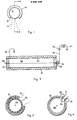
In the drawings - Fig. 1 is an end view of a charging device embodying the invention,
- Fig. 2 is a cross-section through the device of Fig. 1 on the line AA.
- Fig. 3 is an end view in cross-section of another embodiment, and
- Fig. 4 is an end view also in cross-section of a further embodiment of the invention.
- As shown in the drawings, a charging device embodying the invention comprises a
cylindrical housing 10 having asingle aperture 12 through which a sheet of paper shown in dotted outline at 14 can be fed and out of which the paper can exit after having traversed the interior of the cylindrical housing which forms a cylindrical cavity generally designated 16. - The inside surface of the cylindrical wall of the
cavity 16 is coated with a conductive material as denoted byreference numeral 20 in Fig. 2 and for convenience theconductive coating 20 is connected via aconductor 22 to earth (or to one terminal of a high tension source). - In the embodiment shown in the drawings the housing is formed from insulating material and two
circular end caps cylindrical tube 10 to form the cavity and each of theend caps wire electrode 28 which is stretched therebetween. Astop 30 at one end of the wire prevents the wire from pulling through theend cap 24 and atensioning device 32 is located at the other end of thewire 28 so that the latter can be stretched between the twoend caps - A conductor 34 (which may be an extension of the wire 28) connects the latter via a rectifying
device 36 such as a diode to one terminal of the output of ahigh tension source 38 the other terminal of which is connected via aconductor 40 to earth. - Although not shown in detail the source of
potential 38 comprises a piezo-electric crystal with means for squeezing same to produce a high voltage potential acrosss its faces which in turn is conveyed to the two terminals of the source. - As is well known when the squeezing action is released, a potential of equal and opposite polarity is produced across the faces of the crystal and it is for this reason that the diode rectifying
device 36 is incorporated so as to prevent charge of one polarity from reaching theelectrode wire 28. - The conductive interior of the cavity formed by the
lining 20 may be formed by spray painting with a metallic suspension paint onto the interior surface of the electrical insulatingtubular member 10 or by securing a sheet of electrically conductive foil such as aluminium foil onto the interior surface of the cavity by means of an adhesive or the like. - The
aperture 12 allows the paper or otherflexible medium 14 to be fed into and around the interior of the cavity and to exit therefrom. Alternatively two apertures may be provided suitably angled so as to introduce the paper substantially tangentially to the surface of the interior of the cavity and to allow same to leave and the one aperture serves as an inlet and the other as an outlet. - The arcuate extent of the aperture into and from which the flexible material enters and leaves the cavity is as small as possible compatible with the requirement that the flexible material will leave the cavity as shown in Fig. 1. By ensuring that the arcuate extent of the aperture is as small as possible the maximum area of paper is presented to the
electrode wire 28 and by moving the paper around the interior of the cavity so different points on the circumference of thewire electrode 28 are presented to the paper so that on the assumption that the charge distribution around the wire is not necessarily uniform, nevertheless the net effect of presenting the paper to the wire electrode in this way is to cause an integration of the charge over the area of the paper presented thereto over the time period during which it is presented thereto which tends to produce a uniform charge over the area of the flexible material. - Where the flexible material is a coated paper such as zinc oxide coated paper, it is inserted into the
aperture 12 so that the coated surface faces thewire electrode 28. - It has been found by experiment that the voltage required to produce an acceptable level of charge on zinc oxide coated paper to permit photocopying thereon is considerably reduced if a corona charging unit of the type described and shown in Figs. 1 and 2 thereof is employed in place of a conventional charging unit.
- It is important that the flexible material adheres to the inside surface of the cavity and therefore the feed into the cavity should preferably be at a slightly greater rate than the withdrawal traction from the cavity so that the paper is at all times pressed into the curved surface within the cavity. Alternatively, although not shown, the two
end caps - Where this latter feature is incorporated, independent driving wheels (not shown) are preferably provided on the same axis as the
wire electrode 28 so that it is not necessary for the wire to rotate but the latter can remain stationary relative to the cavity. - Fig. 3 shows how a
perforated drum 30 may be situated within thehousing 10 to provide an annular guide for a sheet ofpaper 14. Thedrum 30 is mounted for rotation within thehousing 10. - Fig. 4 illustrates a preferred drive for feeding paper into and extracting paper from a charging unit embodying the invention. To this end three driven
rollers Paper 14 entering the nip betweenrollers housing 10 and will be pulled out through the nip betweenrollers - The feed shown in Fig. 4 may be used in conjunction with a charging device such as shown in Figs. 1 and 2 or with a device such as shown in Fig. 3.
- It is to be understood that the arcuate extent of the wall of the
housing 10 need not be of the order of 300° (i.e. almost full circle) as shown in the drawings, but may be of much smaller arcuate extent I.e. so as to substend for example 180° or thereabouts.
Claims (14)
Applications Claiming Priority (2)
| Application Number | Priority Date | Filing Date | Title |
|---|---|---|---|
| GB7845805 | 1978-11-23 | ||
| GB7845805 | 1978-11-23 |
Publications (2)
| Publication Number | Publication Date |
|---|---|
| EP0020578A1 EP0020578A1 (en) | 1981-01-07 |
| EP0020578B1 true EP0020578B1 (en) | 1983-06-22 |
Family
ID=10501270
Family Applications (1)
| Application Number | Title | Priority Date | Filing Date |
|---|---|---|---|
| EP79901527A Expired EP0020578B1 (en) | 1978-11-23 | 1980-06-03 | Device for electrostatically charging sheet material |
Country Status (5)
| Country | Link |
|---|---|
| US (1) | US4340926A (en) |
| EP (1) | EP0020578B1 (en) |
| JP (1) | JPS55501001A (en) |
| GB (1) | GB2040594B (en) |
| WO (1) | WO1980001112A1 (en) |
Cited By (1)
| Publication number | Priority date | Publication date | Assignee | Title |
|---|---|---|---|---|
| DE102008036244A1 (en) | 2008-08-04 | 2010-02-11 | Ewe Ag | Apparatus for continuous conditioning of stored natural gas |
Families Citing this family (1)
| Publication number | Priority date | Publication date | Assignee | Title |
|---|---|---|---|---|
| DE3544282A1 (en) * | 1985-12-14 | 1987-06-19 | Andreas Ahlbrandt | DEVICE FOR CONTINUOUSLY TREATING SURFACES |
Family Cites Families (3)
| Publication number | Priority date | Publication date | Assignee | Title |
|---|---|---|---|---|
| US2000684A (en) * | 1932-11-21 | 1935-05-07 | Curtis Publishing Company | Opposing offset in printing and the like |
| US2588699A (en) * | 1943-08-27 | 1952-03-11 | Chester F Carlson | Electrophotographic apparatus |
| NL7111963A (en) * | 1970-09-10 | 1972-03-14 |
-
1979
- 1979-11-21 GB GB7940194A patent/GB2040594B/en not_active Expired
- 1979-11-21 JP JP50194579A patent/JPS55501001A/ja active Pending
- 1979-11-21 WO PCT/GB1979/000198 patent/WO1980001112A1/en unknown
- 1979-11-21 US US06/198,950 patent/US4340926A/en not_active Expired - Lifetime
-
1980
- 1980-06-03 EP EP79901527A patent/EP0020578B1/en not_active Expired
Cited By (1)
| Publication number | Priority date | Publication date | Assignee | Title |
|---|---|---|---|---|
| DE102008036244A1 (en) | 2008-08-04 | 2010-02-11 | Ewe Ag | Apparatus for continuous conditioning of stored natural gas |
Also Published As
| Publication number | Publication date |
|---|---|
| GB2040594A (en) | 1980-08-28 |
| WO1980001112A1 (en) | 1980-05-29 |
| EP0020578A1 (en) | 1981-01-07 |
| US4340926A (en) | 1982-07-20 |
| GB2040594B (en) | 1982-12-22 |
| JPS55501001A (en) | 1980-11-20 |
Similar Documents
| Publication | Publication Date | Title |
|---|---|---|
| US3578970A (en) | Variable width corona discharge apparatus with means to shield or vary a predetermined length of a corona discharge wire | |
| JPS5914755B2 (en) | Corona discharge method and corona discharge device | |
| JPH0135702B2 (en) | ||
| US5288305A (en) | Method for charging particles | |
| US3626260A (en) | Method and apparatus for applying voltage in electrophotography | |
| US3390266A (en) | Apparatus for charging the surface of photoelectric layers using corona discharge | |
| US2965756A (en) | Electrostatic charging apparatus | |
| GB994645A (en) | A process and apparatus for electrophotographic development | |
| US3744898A (en) | Corona discharge apparatus | |
| EP0020578B1 (en) | Device for electrostatically charging sheet material | |
| US3075078A (en) | Corona device | |
| US4564282A (en) | Corona charging device | |
| US4110810A (en) | Static charge neutralizer and process | |
| US3603851A (en) | Method of contour charging | |
| US3624392A (en) | Electrophotographic charging apparatus comprising needle point discharge electrodes and concave shield electrodes | |
| KR100576481B1 (en) | Electrostatic processing chamber for arranging in the electrostatic flocking equipment, the electrostatic coating equipment | |
| GB2067523A (en) | Holding sheet material on to a drum | |
| US5933177A (en) | Erase unit for ion deposition web-fed print engine | |
| US5587584A (en) | Apparatus for charging a film on the internal surface of a drum | |
| JPS5522702A (en) | Method and apparatus for removing insulating fluid | |
| JPH0536490A (en) | Static eliminator | |
| US3673472A (en) | Electrostatic photocopying machine | |
| SU504561A1 (en) | Apparatus for applying paintwork material in an electrostatic field | |
| US3201668A (en) | Electrostatic charging apparatus | |
| SU634796A1 (en) | Apparatus for atomizing coating material in electric field |
Legal Events
| Date | Code | Title | Description |
|---|---|---|---|
| PUAI | Public reference made under article 153(3) epc to a published international application that has entered the european phase |
Free format text: ORIGINAL CODE: 0009012 |
|
| AK | Designated contracting states |
Designated state(s): FR NL SE |
|
| 17P | Request for examination filed |
Effective date: 19801030 |
|
| GRAA | (expected) grant |
Free format text: ORIGINAL CODE: 0009210 |
|
| AK | Designated contracting states |
Designated state(s): FR NL SE |
|
| ET | Fr: translation filed | ||
| PG25 | Lapsed in a contracting state [announced via postgrant information from national office to epo] |
Ref country code: SE Effective date: 19831122 |
|
| PGFP | Annual fee paid to national office [announced via postgrant information from national office to epo] |
Ref country code: FR Payment date: 19831130 Year of fee payment: 5 |
|
| PLBE | No opposition filed within time limit |
Free format text: ORIGINAL CODE: 0009261 |
|
| STAA | Information on the status of an ep patent application or granted ep patent |
Free format text: STATUS: NO OPPOSITION FILED WITHIN TIME LIMIT |
|
| PG25 | Lapsed in a contracting state [announced via postgrant information from national office to epo] |
Ref country code: NL Effective date: 19840601 |
|
| 26N | No opposition filed | ||
| NLV4 | Nl: lapsed or anulled due to non-payment of the annual fee | ||
| PG25 | Lapsed in a contracting state [announced via postgrant information from national office to epo] |
Ref country code: FR Free format text: LAPSE BECAUSE OF NON-PAYMENT OF DUE FEES Effective date: 19850731 |
|
| REG | Reference to a national code |
Ref country code: FR Ref legal event code: ST |
|
| EUG | Se: european patent has lapsed |
Ref document number: 79901527.6 Effective date: 19850607 |