EP0020211B1 - Vorrichtung zur Geschwindigkeitsregelung - Google Patents
Vorrichtung zur Geschwindigkeitsregelung Download PDFInfo
- Publication number
- EP0020211B1 EP0020211B1 EP80400631A EP80400631A EP0020211B1 EP 0020211 B1 EP0020211 B1 EP 0020211B1 EP 80400631 A EP80400631 A EP 80400631A EP 80400631 A EP80400631 A EP 80400631A EP 0020211 B1 EP0020211 B1 EP 0020211B1
- Authority
- EP
- European Patent Office
- Prior art keywords
- speed
- value
- signal
- motor
- control
- Prior art date
- Legal status (The legal status is an assumption and is not a legal conclusion. Google has not performed a legal analysis and makes no representation as to the accuracy of the status listed.)
- Expired
Links
- 230000006870 function Effects 0.000 claims description 27
- 238000005259 measurement Methods 0.000 claims description 19
- 230000010363 phase shift Effects 0.000 claims description 6
- 230000008859 change Effects 0.000 claims description 2
- 238000012545 processing Methods 0.000 claims description 2
- 238000012937 correction Methods 0.000 description 6
- 230000003068 static effect Effects 0.000 description 4
- 230000007423 decrease Effects 0.000 description 3
- 230000001960 triggered effect Effects 0.000 description 2
- AZFKQCNGMSSWDS-UHFFFAOYSA-N MCPA-thioethyl Chemical compound CCSC(=O)COC1=CC=C(Cl)C=C1C AZFKQCNGMSSWDS-UHFFFAOYSA-N 0.000 description 1
- 241001122315 Polites Species 0.000 description 1
- 240000008042 Zea mays Species 0.000 description 1
- 230000001133 acceleration Effects 0.000 description 1
- 230000009471 action Effects 0.000 description 1
- 238000007792 addition Methods 0.000 description 1
- 230000033228 biological regulation Effects 0.000 description 1
- 238000001514 detection method Methods 0.000 description 1
- 238000010586 diagram Methods 0.000 description 1
- 230000007717 exclusion Effects 0.000 description 1
- 230000001788 irregular Effects 0.000 description 1
- 238000012986 modification Methods 0.000 description 1
- 230000004048 modification Effects 0.000 description 1
- 230000003287 optical effect Effects 0.000 description 1
- 210000000056 organ Anatomy 0.000 description 1
- 230000036316 preload Effects 0.000 description 1
- 230000001681 protective effect Effects 0.000 description 1
- 230000009467 reduction Effects 0.000 description 1
- 230000006641 stabilisation Effects 0.000 description 1
- 238000011105 stabilization Methods 0.000 description 1
- 230000001360 synchronised effect Effects 0.000 description 1
- 238000012549 training Methods 0.000 description 1
- 230000000007 visual effect Effects 0.000 description 1
Images

Classifications
-
- G—PHYSICS
- G03—PHOTOGRAPHY; CINEMATOGRAPHY; ANALOGOUS TECHNIQUES USING WAVES OTHER THAN OPTICAL WAVES; ELECTROGRAPHY; HOLOGRAPHY
- G03B—APPARATUS OR ARRANGEMENTS FOR TAKING PHOTOGRAPHS OR FOR PROJECTING OR VIEWING THEM; APPARATUS OR ARRANGEMENTS EMPLOYING ANALOGOUS TECHNIQUES USING WAVES OTHER THAN OPTICAL WAVES; ACCESSORIES THEREFOR
- G03B31/00—Associated working of cameras or projectors with sound-recording or sound-reproducing means
- G03B31/04—Associated working of cameras or projectors with sound-recording or sound-reproducing means in which sound track is not on, but is synchronised with, a moving-picture film
-
- H—ELECTRICITY
- H02—GENERATION; CONVERSION OR DISTRIBUTION OF ELECTRIC POWER
- H02P—CONTROL OR REGULATION OF ELECTRIC MOTORS, ELECTRIC GENERATORS OR DYNAMO-ELECTRIC CONVERTERS; CONTROLLING TRANSFORMERS, REACTORS OR CHOKE COILS
- H02P23/00—Arrangements or methods for the control of AC motors characterised by a control method other than vector control
- H02P23/22—Controlling the speed digitally using a reference oscillator, a speed proportional pulse rate feedback and a digital comparator
-
- H—ELECTRICITY
- H02—GENERATION; CONVERSION OR DISTRIBUTION OF ELECTRIC POWER
- H02P—CONTROL OR REGULATION OF ELECTRIC MOTORS, ELECTRIC GENERATORS OR DYNAMO-ELECTRIC CONVERTERS; CONTROLLING TRANSFORMERS, REACTORS OR CHOKE COILS
- H02P5/00—Arrangements specially adapted for regulating or controlling the speed or torque of two or more electric motors
- H02P5/46—Arrangements specially adapted for regulating or controlling the speed or torque of two or more electric motors for speed regulation of two or more dynamo-electric motors in relation to one another
- H02P5/52—Arrangements specially adapted for regulating or controlling the speed or torque of two or more electric motors for speed regulation of two or more dynamo-electric motors in relation to one another additionally providing control of relative angular displacement
- H02P5/56—Speed and position comparison between the motors by electrical means
-
- Y—GENERAL TAGGING OF NEW TECHNOLOGICAL DEVELOPMENTS; GENERAL TAGGING OF CROSS-SECTIONAL TECHNOLOGIES SPANNING OVER SEVERAL SECTIONS OF THE IPC; TECHNICAL SUBJECTS COVERED BY FORMER USPC CROSS-REFERENCE ART COLLECTIONS [XRACs] AND DIGESTS
- Y10—TECHNICAL SUBJECTS COVERED BY FORMER USPC
- Y10S—TECHNICAL SUBJECTS COVERED BY FORMER USPC CROSS-REFERENCE ART COLLECTIONS [XRACs] AND DIGESTS
- Y10S388/00—Electricity: motor control systems
- Y10S388/907—Specific control circuit element or device
- Y10S388/912—Pulse or frequency counter
-
- Y—GENERAL TAGGING OF NEW TECHNOLOGICAL DEVELOPMENTS; GENERAL TAGGING OF CROSS-SECTIONAL TECHNOLOGIES SPANNING OVER SEVERAL SECTIONS OF THE IPC; TECHNICAL SUBJECTS COVERED BY FORMER USPC CROSS-REFERENCE ART COLLECTIONS [XRACs] AND DIGESTS
- Y10—TECHNICAL SUBJECTS COVERED BY FORMER USPC
- Y10S—TECHNICAL SUBJECTS COVERED BY FORMER USPC CROSS-REFERENCE ART COLLECTIONS [XRACs] AND DIGESTS
- Y10S388/00—Electricity: motor control systems
- Y10S388/907—Specific control circuit element or device
- Y10S388/915—Sawtooth or ramp waveform generator
Definitions
- the invention relates to a speed control device, in particular for controlling the movement of an object at a speed equal to a reference value.
- a particular field of application of the invention is that of devices for driving a strip carrying a sound, visual recording or both, the strip having to be driven at a speed defined by a polite signal.
- the pilot signal can be an external signal of given frequency.
- a signal representative of the speed of a band for example the image band, is used to control the engine. drive of the other band.
- the electric motor rotation speed servos used generally have a non-zero static error, for example as a result of the appearance of a resistive torque on the motor shaft.
- the static error is the difference between the reference speed, or setpoint, and the equilibrium speed reached after stabilization of the servo.
- the known systems are generally of the phase locked type between the pilot signal and a signal representative of the actual speed of the soundtrack.
- the locking must be tight enough to obtain the desired precision and stability of control. It follows that the slight but abrupt variations in frequency of the pilot signal, generally made up of a succession of pulses, are reflected on the training of the soundtrack and give rise to an audible cry when their amplitude exceeds a certain threshold.
- the object of the invention is, according to one of its aspects, to produce a control of the rotation speed of an electric motor with zero static error by means of a device of the type comprising a power supply circuit for the motor in electric current, a sensor delivering a measurement signal representative of the actual speed of the motor and a control circuit receiving the measurement signal and delivering a control signal to the supply circuit for controlling the speed of the motor to a predetermined set value.
- Another object of the invention is to produce a control at a reference speed of the running speed of a tape, without repercussions of the significant variations at high frequency of the reference speed, by means of a device of the type comprising a sensor supplying a measurement signal representing the instantaneous actual running speed of the strip, a control loop receiving the measurement signal and a pilot signal and supplying setpoint information to a control circuit of an organ belt drive motor for scrolling it at a reference speed represented by the pilot signal.
- the servo loop includes comparison means receiving the measurement signal and the pilot signal and delivering error information representative of the difference between the real and reference speeds of the strip, and correcting means modifying the setpoint information as a function of the error information, the rate of change of the setpoint information having a maximum value limited in absolute value.
- rate of variation of the setpoint information IC is meant here the values (positive or negative) of ⁇ IC / ⁇ t, IC representing the variation of IC during the time interval At.
- IC can be modified by a positive or negative quantity of fixed predetermined absolute value corresponding to the maximum limit of variation of IC depending simply on the sign of the error information.
- IC is modified, whenever it is necessary, by a positive or negative quantity, the absolute value of which depends on the amplitude of the error information as long as it does not exceed not in absolute value a determined threshold, in which case this quantity remains in absolute value capped at its maximum limit.
- Limiting the variation in time of the setpoint information makes it possible not to pass large and abrupt variations in the reference speed on the tape, the catching up being done gradually.
- An average speed control is therefore carried out with decoupling at high frequencies of variation of the reference speed.
- the error information is not a function of a position difference, but of a speed difference.
- the limit of the variation in absolute value of the setpoint information is chosen to correspond to a predetermined limit in absolute value of the rates of variation of the speed of movement Of the band.
- This speed limit for variation of the speed of travel of the strip is determined so as not to cause audible weeping. It is preferably chosen to be approximately 1% of the reference speed.
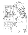
- the coils 14 and 15 are driven by means of electric servo motors (not shown).
- the control of these motors is achieved by well known analog circuits which do not come within the scope of the present invention.
- this control is preferably carried out so as to maintain the arms in substantially fixed positions for which the tensions T and T 'exerted on the strip on either side of the capstan induce an inertial torque thereon. substantially zero.
- this is obtained from the fact that the paths of the strip 10 on each side of the capstan 12 are oriented symmetrically with respect to the diametral plane containing the axis of the capstan and the contact line of the strip thereon.
- the motor 13 When starting, the motor 13 therefore normally has only a small inertial torque to overcome, which makes it possible to very quickly bring the strip 10 to the desired speed. It will also be noted that the strip is simply dragged by adhesion to the smooth capstan, to the exclusion of pinch rollers or pins which can deteriorate it and increase the inertia of the system.
- the strip 10 passes in front of a read head 11 and in front of a sensor 31 which delivers an svb signal representative of the actual running speed of the strip.
- a second sensor 21 is placed on the motor shaft and delivers a signal svm representative of the actual speed of rotation vm of the motor 13.
- the DC motor 13 is supplied with DC by an amplifier 18 which receives a control signal V EN .
- V EN receives a control signal
- the control of the motor 13 is achieved by means of a first loop 20 receiving the signal svm and a setpoint information IC of rotational speed, and delivering the control signal V EN , and of a second loop 30 receiving the signal svb and a pilot signal please, and determining the setpoint information IC so that the strip is driven by the motor 13 at the running speed defined by the pilot signal.
- the loop 20 which controls the real speed of rotation vm of the motor 13 with zero static error in order to rotate the latter at a reference speed VM determined by IC.
- the sensor 21 is for example constituted by an optical disc 21 a integral in rotation with the shaft of the motor 13 and carrying reflective (or transparent) marks distributed angularly in a uniform manner. These marks reflect (or transmit) the light coming from a source on a detector 21b with photosensitive component which produces a pulse with each passage of a mark.
- Such a disc can include for example 1200 marks, which provides a frequency of the output signal svm of 2000 Hz at a nominal speed of tape movement corresponding to a rate of 25 images per second for a tape image.
- Such a sensor is perfectly known per se. There are other types.
- the loop 20 includes a calculating member 24 and a function generator 25.
- This quantity EN is the control information which, converted into analog form by a converter 29 produces the control signal V EN '
- the function f (vm) is a unique and monotonic function of the speed vm.
- the function generator 25 includes a clock 26, a preloading counter 27 and a memory 28.
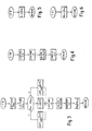
- a monostable flip-flop 23 is triggered by the trailing edges of the pulses S1 and delivers pulses S2 (FIG. 2) of duration T2 which is also significantly less than the Tm period.
- the counting continues with, possibly, one or more returns to zero of the counter when its maximum capacity is exceeded.
- Each trailing edge of a pulse S1 causes the instantaneous content of the counter to be memorized in the memory, which provides the quantity A being a known constant quantity.
- CN EN-IC
- the calculation can also be performed using a microprocessor as described below.
- the mounting of the strip on the capstan can be carried out so that the inertial torque on the capstan is practically zero.
- the counter 27 has a limited capacity, in particular if it returns to zero one or more times during each counting cycle, it is preferable to choose the parameters of the control (K, FO, T2 in particular ) so that at the nominal speed VM the value EN corresponds substantially to half, or even a little less, of the capacity of the counter 27.
- An increase in the value EN is thus authorized in the case where, for example, the torque of the motor must be increased to overcome a sudden resistive torque and we offer possibilities of control in a fairly wide speed range on either side of the nominal speed.
- the precision of the control is linked to the absolute error on the determination of EN.
- the precision is given by FM / FO.
- the second control loop 30 will now be described, the object of which is to determine the setpoint information IC so that the strip 10 runs at a reference speed determined by the pilot signal please.
- the sensor 31 is for example constituted by a light source 31 a and a photosensitive receiver 31 b located on either side of the path of perforations regularly spaced along the strip 10. Other references could be used, for example recordings carried by the tape and detected by appropriate reading means. It is also possible to use the running of the strip itself to drive a wheel with or without spikes whose rotation provides the desired svb signal, or any other running scroll sensor.
- the pilot signal please may be a synchronization signal supplied by an external source or a reference signal representing the speed of movement of a band to which it is desired to control the speed of movement of band 10.
- the sighal please is produced by a sensor 32 analogous to the sensor 31 and delivering a signal of frequency fp proportional to the speed vp of travel of a perforated strip 10 ′ carrying images.
- the proportionality ratios between fb and vb and between fp and vp are equal to K, the number K can for example be equal to 1 if the speeds vb and vp are expressed in images / second.
- the pulses of the svb and svp signals are shaped by means of monostable flip-flops 33, 34 which deliver pulses S3, S4 (FIG. 2) of durations T3, T4 and of frequencies fb and fp, to a circuit 35 which develops error information IE representative of the difference between the speeds vb and vp and which determines the setpoint IC as a function of an initial setpoint value ICO and successive values of the error information.
- the IE information is here developed by measuring the variation in time of the phase shift PH between the signals svb and svp and the rates of variation are determined according to the measured value of E.
- the circuit 35 is represented as being made up of three functional blocks: a counter 36, a first digital calculation unit 37 receiving the content of the counter 36 and developing the value IE and a second digital calculation unit 38 receiving the IE value and developing the IC value.
- the counter 36 counts the pulses S'O of frequency F'O supplied by a clock 39.
- the frequency F'O is chosen to be much higher than fp, for example 2000 Hz.
- the counter 36 contains a number PH ( Figure 2) representing the phase shift between svb and please.
- this operation is carried out for each image, that is to say at a nominal rate of 25 times per second.
- the precision in absolute value over ⁇ PHn is given by the period of the pulses S'O.
- ⁇ ICn depends on that of ⁇ PHn. In the case of the example illustrated, these signs are opposed so that an increase in the phase shift between svb and svp (which translates an acceleration of the band 10 ') results in a reduction in IC, therefore an increase in FM and the speed of reference VM (see equation 1) .
- ⁇ ICn The absolute value of ⁇ ICn is constant and predetermined at a value ⁇ IC max which corresponds substantially to the maximum variation in speed of the strip 10 which is tolerable so as not to generate audible weeping.
- ⁇ IC max The absolute value of ⁇ ICn is constant and predetermined at a value ⁇ IC max which corresponds substantially to the maximum variation in speed of the strip 10 which is tolerable so as not to generate audible weeping.
- Circuit 35 can be implemented in wired logic.
- the calculation units 37 and 38 can then consist of algebraic adder circuits associated in particular with registers for PH, IE, IC and ⁇ IC max.
- the functions performed by the counter 36, the calculation unit 37 and the calculation unit 38 are executed by means of a microprogrammed processing unit (microprocessor), as well as the function performed by the calculation unit 24, the representation of these functional elements in FIG. 1 then having the object of facilitating the understanding of the operation.
- microprocessor microprogrammed processing unit
- the ITP interrupt simply orders the contents of the register [PHn] to be zeroed before returning to the main program.
- the ITI interrupt simply commands the increment of one unit of the content of the register [PHn] before returning to the main program.
- the starting of the servo is done after initial relative positioning of the two strips.
- the servo by means of the loop 30 is not intended to maintain the bands in a relatively predetermined relative position, but to control the speed of the band 10 to that of the band 10 ', the servo being done with decoupling at high frequencies of variation of the speed of the band 10 '.
Landscapes
- Engineering & Computer Science (AREA)
- Power Engineering (AREA)
- Physics & Mathematics (AREA)
- General Physics & Mathematics (AREA)
- Control Of Electric Motors In General (AREA)
- Control Of Eletrric Generators (AREA)
- Electrical Discharge Machining, Electrochemical Machining, And Combined Machining (AREA)
- Control Of Transmission Device (AREA)
- Control Of Velocity Or Acceleration (AREA)
- Magnetic Bearings And Hydrostatic Bearings (AREA)
Claims (10)
wobei der Funktionsgenerator (25) im wesentlichen einen vorladberen Zähler (27) umfaßt, dessen Vorladeeingang mit dem Ausgang der Rechenmittel (24) verbunden ist, dessen Zähleingang mit dem Ausgang des Taktgebers (26) verbunden ist und dessen Zahlsteuereingang Zählsteuersignale empfängt, welche aus dem Meßsignal (svm) erzeugt werden, dessen Frequenz (fm) proportional zur Istgeschwindigkeit des Motors ist.
Priority Applications (1)
| Application Number | Priority Date | Filing Date | Title |
|---|---|---|---|
| AT80400631T ATE8540T1 (de) | 1979-05-23 | 1980-05-09 | Vorrichtung zur geschwindigkeitsregelung. |
Applications Claiming Priority (2)
| Application Number | Priority Date | Filing Date | Title |
|---|---|---|---|
| FR7913211A FR2457595A1 (fr) | 1979-05-23 | 1979-05-23 | Dispositif d'asservissement de vitesse |
| FR7913211 | 1979-05-23 |
Publications (2)
| Publication Number | Publication Date |
|---|---|
| EP0020211A1 EP0020211A1 (de) | 1980-12-10 |
| EP0020211B1 true EP0020211B1 (de) | 1984-07-18 |
Family
ID=9225822
Family Applications (1)
| Application Number | Title | Priority Date | Filing Date |
|---|---|---|---|
| EP80400631A Expired EP0020211B1 (de) | 1979-05-23 | 1980-05-09 | Vorrichtung zur Geschwindigkeitsregelung |
Country Status (5)
| Country | Link |
|---|---|
| US (1) | US4335336A (de) |
| EP (1) | EP0020211B1 (de) |
| AT (1) | ATE8540T1 (de) |
| DE (1) | DE3068581D1 (de) |
| FR (1) | FR2457595A1 (de) |
Families Citing this family (8)
| Publication number | Priority date | Publication date | Assignee | Title |
|---|---|---|---|---|
| FR2620834B1 (fr) * | 1987-09-18 | 1989-12-29 | Travers Pierre | Perfectionnements aux dispositifs et aux bandes de production cinematographiques |
| US4804898A (en) * | 1988-02-22 | 1989-02-14 | Rapid-Air Corporation | Stock feed apparatus |
| US5055756A (en) * | 1988-08-25 | 1991-10-08 | Canon Kabushiki Kaisha | Traverse apparatus and image recording apparatus |
| US5016467A (en) * | 1989-06-07 | 1991-05-21 | Amoco Corporation | Automated flow rate machine |
| FI88015C (fi) * | 1990-12-17 | 1993-03-25 | Kone Oy | Foerfarande foer generering av hastighetsstaellvaerde foer en lyftmotor |
| KR930009229B1 (ko) * | 1991-01-31 | 1993-09-24 | 삼성전자 주식회사 | 캡스턴모터 제어장치 |
| US5880573A (en) * | 1995-06-13 | 1999-03-09 | Texas Instruments Incorporated | Low-cost phase-lock motor control method and architecture |
| JP5340423B2 (ja) * | 2010-01-27 | 2013-11-13 | 三菱電機株式会社 | モータ制御装置 |
Family Cites Families (8)
| Publication number | Priority date | Publication date | Assignee | Title |
|---|---|---|---|---|
| US3137767A (en) * | 1959-04-13 | 1964-06-16 | Clevite Corp | Tape transport mechanism for magnetic recording and/or reproducing apparatus |
| DE1499643C3 (de) * | 1966-04-06 | 1974-02-28 | Robert Bosch Fernsehanlagen Gmbh, 6100 Darmstadt | Anordnung zur Regelung der Laufgeschwindigkeit eines Magnetbandes in Anlagen zur magnetischen Speicherung von Fernsehsignalen |
| GB1426820A (en) * | 1972-04-05 | 1976-03-03 | Hitachi Electronics | Digital control system |
| US3950682A (en) * | 1974-12-19 | 1976-04-13 | International Business Machines Corporation | Digital dc motor velocity control system |
| US4025837A (en) * | 1975-06-30 | 1977-05-24 | International Business Machines Corporation | Adaptive control circuit for a stepping motor |
| JPS5927013B2 (ja) * | 1977-08-05 | 1984-07-03 | 富士通株式会社 | 磁気テ−プ送りモ−タの速度制御方式 |
| JPS5433983A (en) | 1977-08-22 | 1979-03-13 | Toshiba Corp | Digital servo device |
| JPS54102474A (en) * | 1978-01-27 | 1979-08-11 | Sony Corp | Digital servo circuit |
-
1979
- 1979-05-23 FR FR7913211A patent/FR2457595A1/fr active Granted
-
1980
- 1980-05-09 DE DE8080400631T patent/DE3068581D1/de not_active Expired
- 1980-05-09 EP EP80400631A patent/EP0020211B1/de not_active Expired
- 1980-05-09 AT AT80400631T patent/ATE8540T1/de not_active IP Right Cessation
- 1980-05-21 US US06/152,005 patent/US4335336A/en not_active Expired - Lifetime
Also Published As
| Publication number | Publication date |
|---|---|
| FR2457595B1 (de) | 1981-08-21 |
| EP0020211A1 (de) | 1980-12-10 |
| FR2457595A1 (fr) | 1980-12-19 |
| ATE8540T1 (de) | 1984-08-15 |
| DE3068581D1 (en) | 1984-08-23 |
| US4335336A (en) | 1982-06-15 |
Similar Documents
| Publication | Publication Date | Title |
|---|---|---|
| US4448368A (en) | Control for tape drive system | |
| EP0020211B1 (de) | Vorrichtung zur Geschwindigkeitsregelung | |
| FR2512571A1 (fr) | Appareil pour l'affichage d'une donnee stockee en memoire | |
| FR2501175A1 (fr) | Circuit de reglage de concordance de position pour machine a couper des etiquettes | |
| FR2556674A1 (fr) | Methode et configuration de circuits pour supprimer les actions de regulation indesirables dans les systemes de freinage a glissement regule | |
| FR2503434A1 (fr) | Dispositif d'entrainement d'un ruban tel qu'un dispositif d'entrainement d'une bande magnetique | |
| FR2470505A1 (fr) | Generateur de cadence de comptage de temps | |
| FR2488024A1 (fr) | Systeme d'asservissement a courants de foucault pour la commande de la rotation de chargeurs de disques | |
| FR2530358A1 (fr) | Circuit d'asservissement numerique comportant notamment un compteur a n bits | |
| FR2514541A1 (fr) | Appareil pour reproduire un disque tel qu'un disque audio a signaux numeriques pcm | |
| EP0174408A1 (de) | Steuerung einer elektronischen Vorrichtung mittels konstanter Ladung für einen kapazitiven Motor, insbesondere für ein Winkelbeschleunigungs- oder Beschleunigungsmessgerät | |
| EP0002412B1 (de) | Verfahren und Vorrichtung für die Synchronisierung der Wiedergabe von akustischer und visueller Information | |
| EP0322177B1 (de) | Steuervorrichtung zum Anhalten einer Motorwelle | |
| FR2620243A1 (fr) | Procede de reacquisition de la position de tangage d'un satellite terrestre | |
| US3943565A (en) | Track scan initiation and cutout arrangement for a helical scan video recorder | |
| US4471272A (en) | Circuit for controlling the speeds of two capstans | |
| FR2470506A1 (fr) | Dispositif de freinage d'un moteur de rotation, et lecteur de videodisque comprenant un tel dispositif | |
| EP0031754B1 (de) | Bandlaufwerk mit zwei Antriebsrollen und Vorrichtungen zur Steuerung der Bandspannung | |
| FR3101704A1 (fr) | Procédé de détection d’une position angulaire absolue ou d’une course de déplacement angulaire absolue d’un organe tournant | |
| CH714759B1 (fr) | Mécanisme d'affichage d'horlogerie sautant et régulé. | |
| JPH0237033B2 (ja) | Teepuryokenshutsusochi | |
| FR2535505A1 (fr) | Dispositif d'affichage du defilement d'une bande magnetique pour un appareil d'enregistrement et/ou de reproduction | |
| FR2467461A1 (fr) | Dispositif de commande du moteur de rotation d'un lecteur de videodisque, et lecteur de videodisque comprenant un tel dispositif | |
| FR2480473A1 (fr) | Procede et appareil de restitution d'un signal enregistre sur un support defilant | |
| FR2465292A1 (fr) | Perfectionnement relatif a des mecanismes d'entrainement de la bande pour enregistreurs et lecteurs a bande magnetique, en particulier du type a cassette |
Legal Events
| Date | Code | Title | Description |
|---|---|---|---|
| PUAI | Public reference made under article 153(3) epc to a published international application that has entered the european phase |
Free format text: ORIGINAL CODE: 0009012 |
|
| AK | Designated contracting states |
Designated state(s): AT CH DE GB IT |
|
| 17P | Request for examination filed |
Effective date: 19810429 |
|
| ITF | It: translation for a ep patent filed | ||
| GRAA | (expected) grant |
Free format text: ORIGINAL CODE: 0009210 |
|
| AK | Designated contracting states |
Designated state(s): AT CH DE GB IT LI |
|
| REF | Corresponds to: |
Ref document number: 8540 Country of ref document: AT Date of ref document: 19840815 Kind code of ref document: T |
|
| REF | Corresponds to: |
Ref document number: 3068581 Country of ref document: DE Date of ref document: 19840823 |
|
| PLBE | No opposition filed within time limit |
Free format text: ORIGINAL CODE: 0009261 |
|
| STAA | Information on the status of an ep patent application or granted ep patent |
Free format text: STATUS: NO OPPOSITION FILED WITHIN TIME LIMIT |
|
| 26N | No opposition filed | ||
| PGFP | Annual fee paid to national office [announced via postgrant information from national office to epo] |
Ref country code: AT Payment date: 19860530 Year of fee payment: 7 |
|
| PG25 | Lapsed in a contracting state [announced via postgrant information from national office to epo] |
Ref country code: AT Effective date: 19870509 |
|
| PG25 | Lapsed in a contracting state [announced via postgrant information from national office to epo] |
Ref country code: LI Effective date: 19870531 Ref country code: CH Effective date: 19870531 |
|
| REG | Reference to a national code |
Ref country code: CH Ref legal event code: PL |
|
| PG25 | Lapsed in a contracting state [announced via postgrant information from national office to epo] |
Ref country code: DE Effective date: 19880202 |
|
| GBPC | Gb: european patent ceased through non-payment of renewal fee | ||
| PG25 | Lapsed in a contracting state [announced via postgrant information from national office to epo] |
Ref country code: GB Free format text: LAPSE BECAUSE OF NON-PAYMENT OF DUE FEES Effective date: 19881118 |