EP0019559A1 - Procédé de régulation de circulation de véhicules, dispositif pour la mise en oeuvre de ce procédé et application de ce dispositif à la simulation de trafic - Google Patents
Procédé de régulation de circulation de véhicules, dispositif pour la mise en oeuvre de ce procédé et application de ce dispositif à la simulation de trafic Download PDFInfo
- Publication number
- EP0019559A1 EP0019559A1 EP80400700A EP80400700A EP0019559A1 EP 0019559 A1 EP0019559 A1 EP 0019559A1 EP 80400700 A EP80400700 A EP 80400700A EP 80400700 A EP80400700 A EP 80400700A EP 0019559 A1 EP0019559 A1 EP 0019559A1
- Authority
- EP
- European Patent Office
- Prior art keywords
- vehicles
- traffic
- sensors
- critical
- airlock
- Prior art date
- Legal status (The legal status is an assumption and is not a legal conclusion. Google has not performed a legal analysis and makes no representation as to the accuracy of the status listed.)
- Ceased
Links
- 230000001105 regulatory effect Effects 0.000 title claims abstract description 24
- 238000000034 method Methods 0.000 title claims description 22
- 238000004088 simulation Methods 0.000 title claims description 6
- 230000033228 biological regulation Effects 0.000 claims abstract description 47
- 238000013459 approach Methods 0.000 claims description 79
- 238000012545 processing Methods 0.000 claims description 30
- 230000006870 function Effects 0.000 claims description 25
- 238000011144 upstream manufacturing Methods 0.000 claims description 19
- 238000010521 absorption reaction Methods 0.000 claims description 16
- 239000012530 fluid Substances 0.000 claims description 12
- 239000007789 gas Substances 0.000 claims description 12
- 230000007423 decrease Effects 0.000 claims description 8
- 230000011664 signaling Effects 0.000 claims description 8
- 230000001276 controlling effect Effects 0.000 claims description 6
- 241001465382 Physalis alkekengi Species 0.000 claims description 5
- 230000010365 information processing Effects 0.000 claims description 3
- 230000000903 blocking effect Effects 0.000 claims description 2
- 230000014759 maintenance of location Effects 0.000 claims description 2
- 125000004122 cyclic group Chemical group 0.000 claims 1
- 239000013589 supplement Substances 0.000 claims 1
- 230000032258 transport Effects 0.000 description 55
- 230000033001 locomotion Effects 0.000 description 14
- 238000005054 agglomeration Methods 0.000 description 12
- 230000002776 aggregation Effects 0.000 description 12
- 230000008859 change Effects 0.000 description 11
- 230000006735 deficit Effects 0.000 description 7
- 210000001015 abdomen Anatomy 0.000 description 5
- 230000004048 modification Effects 0.000 description 5
- 238000012986 modification Methods 0.000 description 5
- 238000003915 air pollution Methods 0.000 description 4
- 230000008901 benefit Effects 0.000 description 4
- 230000009931 harmful effect Effects 0.000 description 4
- 230000009467 reduction Effects 0.000 description 4
- 230000006978 adaptation Effects 0.000 description 3
- 239000000446 fuel Substances 0.000 description 3
- 230000008520 organization Effects 0.000 description 3
- 230000008569 process Effects 0.000 description 3
- 229920006395 saturated elastomer Polymers 0.000 description 3
- DGAQECJNVWCQMB-PUAWFVPOSA-M Ilexoside XXIX Chemical compound C[C@@H]1CC[C@@]2(CC[C@@]3(C(=CC[C@H]4[C@]3(CC[C@@H]5[C@@]4(CC[C@@H](C5(C)C)OS(=O)(=O)[O-])C)C)[C@@H]2[C@]1(C)O)C)C(=O)O[C@H]6[C@@H]([C@H]([C@@H]([C@H](O6)CO)O)O)O.[Na+] DGAQECJNVWCQMB-PUAWFVPOSA-M 0.000 description 2
- 239000006096 absorbing agent Substances 0.000 description 2
- 230000009471 action Effects 0.000 description 2
- 230000000712 assembly Effects 0.000 description 2
- 238000000429 assembly Methods 0.000 description 2
- 230000006399 behavior Effects 0.000 description 2
- 239000003086 colorant Substances 0.000 description 2
- 230000001934 delay Effects 0.000 description 2
- 230000000694 effects Effects 0.000 description 2
- 238000005286 illumination Methods 0.000 description 2
- 230000003993 interaction Effects 0.000 description 2
- 229910001507 metal halide Inorganic materials 0.000 description 2
- 150000005309 metal halides Chemical class 0.000 description 2
- 238000011160 research Methods 0.000 description 2
- 229910052708 sodium Inorganic materials 0.000 description 2
- 239000011734 sodium Substances 0.000 description 2
- 230000007704 transition Effects 0.000 description 2
- RZVAJINKPMORJF-UHFFFAOYSA-N Acetaminophen Chemical compound CC(=O)NC1=CC=C(O)C=C1 RZVAJINKPMORJF-UHFFFAOYSA-N 0.000 description 1
- UGFAIRIUMAVXCW-UHFFFAOYSA-N Carbon monoxide Chemical compound [O+]#[C-] UGFAIRIUMAVXCW-UHFFFAOYSA-N 0.000 description 1
- 241000196324 Embryophyta Species 0.000 description 1
- 241001465754 Metazoa Species 0.000 description 1
- 230000002159 abnormal effect Effects 0.000 description 1
- 230000005540 biological transmission Effects 0.000 description 1
- 229910002091 carbon monoxide Inorganic materials 0.000 description 1
- 230000015556 catabolic process Effects 0.000 description 1
- 238000010276 construction Methods 0.000 description 1
- 230000006378 damage Effects 0.000 description 1
- 230000002950 deficient Effects 0.000 description 1
- 238000010586 diagram Methods 0.000 description 1
- 230000005611 electricity Effects 0.000 description 1
- 230000002349 favourable effect Effects 0.000 description 1
- 230000012447 hatching Effects 0.000 description 1
- 230000036541 health Effects 0.000 description 1
- 238000013178 mathematical model Methods 0.000 description 1
- 238000005259 measurement Methods 0.000 description 1
- 230000035515 penetration Effects 0.000 description 1
- 230000003449 preventive effect Effects 0.000 description 1
- 230000004044 response Effects 0.000 description 1
- 230000000717 retained effect Effects 0.000 description 1
- 238000012216 screening Methods 0.000 description 1
- 230000001235 sensitizing effect Effects 0.000 description 1
- 230000001360 synchronised effect Effects 0.000 description 1
- 230000029305 taxis Effects 0.000 description 1
- 238000012360 testing method Methods 0.000 description 1
- 230000001052 transient effect Effects 0.000 description 1
- 230000001960 triggered effect Effects 0.000 description 1
- 238000012800 visualization Methods 0.000 description 1
Images
Classifications
-
- G—PHYSICS
- G08—SIGNALLING
- G08G—TRAFFIC CONTROL SYSTEMS
- G08G1/00—Traffic control systems for road vehicles
- G08G1/07—Controlling traffic signals
- G08G1/081—Plural intersections under common control
Definitions
- the present invention relates to a vehicle traffic control method, a device for implementing this method as well as an application of this device to the simulation of motor vehicle traffic, according to predetermined parameters.
- This invention is particularly applicable to the regulation of large urban traffic; it makes it possible to avoid traffic jams in critical passages, to increase the speed of circulation of priority vehicles such as public transport vehicles or emergency vehicles, to reduce the rate of atmospheric pollution due to exhaust gases vehicles, as well as the rate of noise pollution due to noise produced by moving vehicles, or pollution due to vibrations; this invention also makes it possible to regulate the speed of vehicles circulating in an urban agglomeration, which very significantly promotes energy savings.
- the invention makes it possible to best manage the availability of parking lots and also promotes savings in the energy consumed both by traffic control lights and by public lighting.
- Known systems for regulating circulation are generally "open loop" regulation systems. As will be seen below in detail, these systems do not make it possible to obtain an image of the circulation and in particular of the various momentary disturbances which it undergoes, or which it causes. As a result, these systems cannot adapt the regulation to disturbances.
- traffic control system controlled and monitored by a central station. This central station controls several semi-autonomous servo sets which regulate traffic in predetermined areas.
- these slave assemblies being semi-autonomous, it is impossible to react very quickly, in real time, when a disturbance occurs at one of these semi-autonomous assemblies.
- Another type of system is also known which makes it possible to adjust the traffic lights on different axes leading to a junction or critical passage, in a concentric manner with respect to this passage. Theoretically, this L. Concentric adjustment of the timing of the lights in relation to the critical passages should produce a uniform flow of traffic across the whole area surrounding the critical passage. In fact, this system does not take into account the disturbances that can occur along an axis leading to the critical passage; as all the axes which lead to this critical passage are regulated concentrically, it follows that a disturbance on one axis cannot be taken into account without disturbing the regulation of traffic on the other axes.
- This system does not ensure maximum vehicle throughput at critical passages; moreover, it does not take into account the degree of pollution by the exhaust gases or of noise pollution due to the vehicles being in the critical passage and on the various axes which lead to this passage.
- These systems also do not allow the establishment of specific plans to ensure the best possible movement of priority vehicles such as public transport vehicles or emergency vehicles (firefighters, ambulances ).
- Another known system consists in controlling the signaling lights according to a determined number of time plans, adapted to the different variations in traffic occurring at determined times of the day.
- Such a system comprises, for each signaling light, an individual synchronization arrangement whose setting can be modified, either directly near the light, or from a central control station.
- This central control station includes recorded traffic plans, chosen as models and corresponding to the different variations in traffic at characteristic times of the day. It is obvious that such a system does not work in real time, since the light timers are controlled from a central station auguel a traffic model is imposed.
- This system has the disadvantage of not being able to adapt the regulation of the various signaling lights to actual traffic and in particular to disturbances that this traffic can undergo.
- the central system continues to operate according to the model imposed on it, without being able to take this disturbance into account.
- this system does not take into account the presence of priority vehicles in traffic, nor very important parameters such as the degree of pollution, either noise or gas; nor does it allow the speed of vehicles to be regulated as a function of the energy savings to be achieved.
- Another disadvantage of existing systems is that they do not allow sufficient performance to be obtained from the road network.
- the main causes of this lack of efficiency are the total absence of automatic regulation of the two circulation systems, in a closed loop, controlling, on the one hand, the demand for vehicles entering on high traffic axes, and on the other hand the maximum flow that these axes can accept.
- Another disadvantage of existing systems is that they take no account of pollution, either atmospheric or noise, caused by the movement of vehicles.
- the main causes of this insufficiency are due to the total absence of control of the sources of pollution, to the absence of control and intervention, in real time, on the sources of pollution, according to the degree of pollution reached.
- the result is a sharp increase in pollution rates in heavily congested areas and even exceeding dangerous pollution thresholds, either noise or atmospheric.
- the existing systems also do not make it possible to achieve energy savings, although studies have shown that on a given route, a reduction in journey time of 10%, makes it possible to achieve a fuel saving of approximately 6%.
- This inability to achieve energy savings results mainly from the fact that the existing systems do not include any provision making it possible to contain, when stationary, all the excess vehicles heading for a critical passage.
- public lighting retains a fixed light intensity, while this, in order to save energy, should be regulated according to the surrounding light intensity and the traffic on the different lanes. of the network. This results in very high fuel consumption as well as excessive consumption of energy intended for public lighting.
- the object of the invention is to remedy these drawbacks and, in particular, to allow, by means of a method and a device allowing the implementation of this method and having great adaptability, to regulate the circulation of vehicles, in particular in the middle urban. It makes it possible to regulate this circulation, in real time, as a function of various parameters relating to this circulation, these parameters being able to vary in great proportions, as a function of various disturbances that the circulation may undergo; it also allows regulation of the circulation of priority vehicles such as public transport vehicles or emergency vehicles, without having to provide permanent traffic lanes on the cnaussée which reduce the number of vehicles that can circulate on axes leading to critical passages.
- priority vehicles such as public transport vehicles or emergency vehicles
- corridors for priority public transport vehicles are temporarily delimited in the control airlock, as a function of the speed of vehicle arriving in the airlock, and the length of the queue. of the various vehicles, at the entrance to the link with maintained fluid circulation.
- the fire timing plans are applied in real time as a function of an additional parameter relating to the degree of pollution caused by the vehicles on each axis, and to critical passages.
- the respective routes are defined for the priority emergency vehicles, then the crossing of the lights on each corresponding route is released, in advance of the arrival of the emergency vehicle, as a function of the speed of it.
- the intensity of illumination of the regulation lights and of the street lighting street lamps is varied, as a function of the light intensity of the natural light and of the vehicle flow rate on the different axes.
- the subject of the invention is also a device for regulating the circulation of vehicles in an area having at least one critical passage and at least one main axis which leads to this critical passage, secondary tracks opening onto each main axis and traffic lights.
- traffic control being arranged at least at the intersections of the secondary tracks and the main axes and at the intersections of the main axes and the critical passage, each main axis having, from the corresponding critical passage, successively at least one portion of axis or link approach to the critical passage, with maintained fluid circulation, and at least a portion of axis or airlock of regulation, with controlled circulation
- this device comprising an information processing system, constituted by at least one memory associated with a commanding processor the timing of the lights, according to control plans recorded in memory, characterized in that it comprises in the link of each main axis, a counter connected to the treatment system and capable of indicating the flow of vehicles in this link and, in the link and the control airlock, of the sensors associated with the treatment system, these sensors being able to determine relative parameters the
- the processor operates cyclically, one of the cycles being a cycle for recording the parameters read by the sensors and the flow rate recorded by the meter, the next cycle being a fire timing control cycle according to the plan corresponding to the saved parameters.
- the device also comprises pollution sensors, capable of determining the degree of pollution caused by the different vehicles on each axis and at critical passages.
- the link of a main axis includes several queue length sensors, located at increasing distances from the critical passages.
- the queue length sensors in the secondary tracks are all the more distant from the main axis on which these tracks open, as these tracks are distant from the critical passage.
- the maximum vehicle throughput that the critical passage can absorb being predetermined, the time delay control plane selected in memory by the processor for each axis, is that which, according to the various parameters, makes it possible to control the time delays of the lights in the airlock and in the link of each axis so that the flow of vehicles admitted to the critical passage does not exceed the maximum flow admissible by the critical passage on the axis in question.
- the fire timing control plan selected in memory by the processor is a plan for increasing the vehicle hold time in the control lock .
- the special control plan for public transport vehicles is selected in memory by the processor when public transport vehicles are moving on the axis, and when the maximum flow of vehicles that the critical passage can absorb has caused the prior establishment of a time increase plan vehicle restraint in the control lock.
- the device further comprises, in the airlock and upstream thereof, sensors or beacons sensitive to the presence of a public transport vehicle on the axis in question, these sensors being connected to the treatment system, indicator means for setting up a special corridor for public transport vehicles in the control airlock, these special corridor indicator means being made aware when the special plan for public transport vehicles is selected by the processor, the sensors sensitive to public transport vehicles being arranged in the vicinity of each intersection of a secondary lane with the main axis, so as to identify the presence and the nature of the priority vehicle and its speed of progression, so that the processor regulates this speed from the special plan already in place for these public transport vehicles.
- the device also comprises, at the starting point of the emergency vehicles, means connected to the processor so that the latter selects in memory a special fire timing plan for emergency vehicles, corresponding to the route that each emergency vehicle must use as well as the number of emergency vehicles having to use the same route simultaneously.
- the device comprises sensors sensitive to the presence of emergency vehicles, these sensors being located on each journey at least near the regulation lights, these sensitive sensors being connected to the processing system for that it controls the lights on each trip predetermined, according to the corresponding special emergency plan, by releasing the crossing of lights ahead of the arrival of each emergency vehicle, this advance being a function of the speed of the emergency vehicle on this route.
- the device further comprises counters, connected to the processing system, 'capable of counting the parking spaces available in different parking lots and display means connected to the processing unit, capable of displaying on the various main axes leading to the critical passage, the availability of parking spaces in these different parks.
- the device comprises light intensity sensors in the environment of the main axes and secondary paths, these sensors being connected to the processing system so that the processor selects in memory an intensity adjustment plan.
- signal lights and public lighting lanterns located along the axes and lanes, depending on the surrounding light intensity and the flow of vehicles on these axes and lanes.
- the processing systems of the different zones are linked to a central processing and control system capable of exchanging information with these zone processing systems, so as to be able to replace any of these area treatment systems.
- the device of the invention applies to the simulation of motor vehicle traffic, as a function of predetermined parameters.
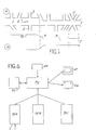
- FIG. 1 there is shown in (a) a main axis of circulation 1 leading to a critical passage C; secondary routes2,3 lead to this main axis.
- Traffic control lights (not shown in the figure) are arranged at each of the crossroads between the main axis 1 and the secondary tracks 3; these lights are constituted in a known manner, for example by the association of three lamps of different colors; two of these lamps, green or red, authorize or prohibit traffic, while the third announces a switch between the two previous lamps.
- Critical passage C can be considered as a passage whose absorption possibilities of vehicles in circulation are reduced during periods of heavy traffic.
- a portion of the main axis 1, in the vicinity of the critical passage can be defined as an approach link to the critical passage while a control airlock is defined upstream of the link d 'approach.
- the approach link and the critical crossroads present a deficit in vehicles, while the control airlock presents a surplus flow, in f busy traffic period.
- the neck 8 represents the bottleneck or approach link with a deficit flow
- the shoulder 9 corresponds to the transition between the belly 10 or airlock of regulation, with excess flow
- the approach link 8 As will be seen below, the neck 8 or approach link can be qualified as a portion with maintained fluid circulation, while the belly 10 or airlock can be qualified as a portion with controlled circulation.
- the orifice 7 of the bottle indicates the limit des'possibilities of vehicle traffic flow, at the critical end of the main axis.
- the belly 10 jcue the role of airlock which allows to retain excess vehicles, in sections of track where their stopping does not risk disturbing the rest of the traffic, when the vehicles which must enter the deficit approach link, are in excess in relation to the possibilities of absorption of this link and of the critical passage C.
- the control airlock therefore represents a portion of track of which the capacity appears excess. It is for example the portion starting from the left end of the axis for example the portion starting from the left end of the axis and going up to the level of tracks 2 and 3. A slight delay caught in this airlock Regulation prevents blocking of vehicles at the approach link and critical passage and thus saves them considerable time.
- the method and the system of the invention consist, when the airlock is crossed, of maintaining the fluidity of the circulation of vehicles in the approach link 8, up to the exit 7 of the link corresponding to the critical passage. It is thus possible, thanks to this image of traffic, on each main axis leading to a critical passage, to cut out an urban agglomeration, for example, according to zones each comprising a critical passage and at least one main axis having at least one link with circulation with maintained fluidity, and an airlock with regulation with circulation with controlled fluidity; these two main axis portions form a deficit-surplus couple. These zones being defined, it is then necessary to determine on each main axis the maximum flow of vehicles that the critical passage and the link with fluid circulation can absorb.
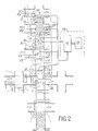
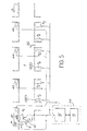
- FIG 2 there is shown schematically the traffic control device, according to the invention, applied to traffic control on main axes arriving at a critical intersection C.
- the description of this device and its operation will also allow a better understanding of the progress of the process according to the invention.
- the fictitious images in the form of bottles, which can be attributed to each of the main axes; the belly 10 of these bottles defines on each main axis, a control airlock 11, represented by hatching spaced in the figure.
- the bottlenecks or approach links of the critical passage C are represented at 8.
- the traffic can be qualified as “controlled” in the airlock 11, and can be described as "maintained fluid circulation", in the approach link 8.
- various signaling lights such as 12, 13, located either on the secondary channels 3, ie on the main axis 1.
- the device of the invention comprises an information processing system 14, consisting of at least one memory 15, associated with a processor 16, controlling the timing of different traffic lights such as 12, 13.
- these traffic lights which are represented in the figure by a circle are lights of known type, constituted by three lamps of different colors red, green and orange, for example.
- the processor 16 controls the timing of the lights on the main axes and on the secondary tracks, according to control plans which are recorded in memory and which will be described later in detail.
- the device also includes a counter such as 17, located in the approach link of each main axis and which is connected to processor 16 of the processing system.
- a counter such as 17, located in the approach link of each main axis and which is connected to processor 16 of the processing system.
- Each speedometer and a speed sensor, adjacent to the speedometer and not shown, on the corresponding main axis, are capable of indicating the flow and the speed of the vehicles in each approach link, so that the processing system is informed at at all times of the speed and number of vehicles absorbed by this approach link, and so that the various lights can be regulated so that the flow of vehicles entering each approach link is not greater than the flow of vehicles that can be absorbed by the critical passage C.
- Sensors capable of determining parameters relating to the length of the queues of vehicles in the approach link, in the control lock and in the secondary tracks, as well as parameters relating to the nature and advance of the priority vehicles, are arranged in the link, the control airlock, and the secondary tracks; these different sensors are connected to processor 16 so that the latter, according to these different parameters at flow, controls the timing of the various lights according to the corresponding plan saved in memory.
- these various sensors, as well as their locations will be described later in detail.
- the processor operates cyclically: the parameter delivered by each sensor is taken into account by the computer every half-second, for example.
- the computer using predetermined plans recorded in memory 15, applies the corresponding fire plan.
- This traffic light plan allows the processor to control the timing of the various traffic lights and in particular the green times, that is to say free traffic times, granted to each of the paths leading to the crossroads. It also determines the time differences to be expected between the crossroads, for the establishment of green waves on the main axes.
- the foreground of lights has a cycle of 100 seconds which, in regulating the circulation of each main axis, does not encroach too much on the comfort of pedestrians and users of secondary roads.
- 100 seconds is the maximum discomfort that can be imposed on pedestrians who want to cross a main axis or on users of secondary roads who want to lead to or cross this main axis.
- a fire plan that ensures maximum comfort has a cycle time of 60 seconds.
- This 60-second cycle is a minimum cycle and thus the time separating 60 seconds from 100 seconds has been divided into 5-second increments, so that for each 5-second stage, a new fire plan is established.
- each demarcated area has nine fire plans.
- the transition from a determined fire plan to a higher fire plan is carried out following the recording of the parameters indicated by the various sensors, when this recording shows that the volume of traffic in progress causes difficulties. traffic. This gradual application of the various fire plans is very closely linked to traffic demand, at the entry of the approach link.
- the critical intersection C shown diagrammatically in FIG. 2 represents major crossings of the agglomeration, towards which large streams of traffic converge; this critical crossroads presents a limit of absorption capacity of vehicles, of a whole sector.
- Approach 8 marriages are the last links that allow vehicle flows to access the critical crossroads.
- the absorption of circulation by these links is deficient compared to the main axis portions located upstream. It is essentially necessary to maintain the fluidity of the circulation of vehicles in these links, in order to preserve their capacity, on pain of arbitrarily and unnecessarily reducing the possibilities of circulation offered in a whole sector. We will see later in detail how this fluidity is maintained.
- the regulation airlocks such as 11 are located upstream of the approach links and they offer a very excess capacity compared to that of the links located downstream, either because of their configuration, or because of the short green light time which is granted to them.
- the assembly constituted by the critical crossroads, the approach link and the control airlock on each main axis constitutes a fundamental element in the functioning of the system according to the invention. This set makes it possible to promote optimal exploitation of the road network in the agglomeration.
- this fundamental element is represented schematically by a bottle, the orifice of which delimits the maximum capacity of the axis in question.
- the neck of the bottle constitutes the approach link, it is a deficit link and its capacity must be preserved at all costs.
- the shoulder 9 of the bottle constitutes one of the main valves for access to the approach link and to the critical crossroads; this valve allows to accept in the approach link only a flow of vehicle conforming to that which the critical crossroads can absorb.
- the belly 10 of the bottle which contains the airlock 11 constitutes a portion of main axis which provides excess capacity; it is in this airlock that it is possible to create, as we will see from the sufte, traffic lanes for public transport vehicles for example.
- Figure 2 we have described in detail only the main axis 1, but it is obvious that the other main axes leading to the critical intersection C are defined and cut in the same way.
- the information provided by the sensors allows the processor to choose a fire plan adapted to the current situation. This fire plan is maintained throughout the duration of a cycle, that is to say that its time base is between 60 and 100 seconds.
- the sensors 18, 19, 20 located in the approach link 8 are sensors making it possible to indicate the length of the queues of the vehicles, when the traffic light 21 prohibits the passage of the vehicles towards the critical crossroads, c 'ie when this light is red for example.
- the sensors 18, 19, 20 are located at increasing distances from the critical intersection C. They can be constituted for example by magnetic loops, sensitive to the presence of vehicles.
- the sensors 18 and 19 can be qualified respectively as queue length, 1st degree or 2nd degree sensors.
- the queue length sensor 20 can be described as an anti-blocking sensor and can be constituted, like sensors 18 and 19, by a magnetic loop.
- This sensor makes it possible, during a serious disturbance, when the critical crossroads has a clearly insufficient vehicle absorption capacity, to prevent the queue of vehicles waiting in the approach link 8 from encroaching on the intersection between the main track 1 and the secondary track 22.
- the length of the vehicle queue goes up to the sensor 20, it is absolutely necessary to keep the vehicles waiting in the airlock, by red light 23, until the approach link has been removed.
- the counter 17 makes it possible to count vehicles passing through the approach link. It also makes it possible, via the processor 16, as will be seen below, to ensure maximum throughput of vehicle traffic in this approach link.
- the timing control plan for the lights selected in memory by the processor is a plan for increasing the holding time of the vehicles in the control lock.
- Sensors 23 make it possible to determine the length of the queues of vehicles in the secondary tracks; they are arranged on each of these tracks at distances dl, d2, d3, increasing with respect to the axis main 1, as or as it moves away from the critical junction C. Beyond a certain distance from a secondary junction to the critical junction, the queue length sensors are placed near the crossroads. These magnetic type sensors, for example, allow the processor 16 to be informed of the length of the vehicle queues on each of the secondary tracks. It is essential that the queue of vehicles waiting in a secondary lane, near the critical junction, be shorter than the queue of vehicles in a secondary lane distant from the critical junction.
- the control airlock 11 also includes sensors for queue lengths 24, of the magnetic type for example, which can be described as "anti-lock” and which make it possible to control the timing of lights such as 13, so that the queue of vehicles in the control lock, do not encroach on the intersection between the main track 1 and the secondary track 24.
- control lock can be cut into slices, between its entry and exit, so as to release towards the approach link only the number of vehicles contained in one or more sections, and which can be absorbed by this approach link.
- system shown in the figure also includes sensors such as 25, connected to the computer 16 and making it possible to determine the degree of gas and / or sound pollution caused and / or pollution by vibrations. These different types of pollution can be caused by moving vehicles. Only one type of sensor has been shown to measure the degree of pollution, but it is obvious that there can be one type of sensor per type of pollution. These sensors, as a function of the parameters which they supply to the computer 16, make it possible to regulate the speed of moving vehicles, so that the pollution created by the vehicles never exceeds the predetermined limits.
- This speed can be known depending on the results delivered by the meters 17 the regulation of this speed is also important because it is very closely linked to the energy consumed by moving vehicles.
- Other sensors such as 26, connected to the computer 16 make it possible to determine the light intensity, in the environment of the main axes and the secondary paths, so that the processor 16 selects in memory a light intensity adjustment plan.
- traffic lights and public lighting lanterns not shown, located along the main axes and secondary roads, depending on the surrounding light intensity and the flow of vehicles on the main axes and secondary roads.
- the information thus received by the processor allows it to choose a fire plan suited to the situation at hand; this fire plan is kept for the entire duration of a cycle, that is to say that its time base is of the order of 60 to 100 seconds.
- the construction of a plan begins with the study of the possibilities of absorption of the critical crossroads, from which the distribution of the timing of the green lights directly follows on each axis leading to this critical crossroads.
- the processor controls the green times to be granted at each intersection of the main axis with a secondary lane , so that the critical intersection constantly absorbs a maximum flow of vehicles, especially in busy traffic periods.
- the processor controls the green times required at each crossroads .
- the processor thus establishes a green wave which allows the vehicles which are admitted at the head on the axis considered to traverse the approach link, without being stopped.
- the choice of fire plan is made exclusively according to the volume of vehicles, that is to say according to the number of vehicles wishing to cross the critical intersection.
- the counters 17 located in the approach blocks of a critical crossroads inform the processor about the volume of traffic going towards the crossroads.
- the processor determines whether the intersection can absorb all of the vehicles that arrive at the entrance to the approach link; if the capacity of this intersection appears too low, the processor selects in memory a higher traffic light plan, which makes it possible to increase the capacity of the intersection.
- the processor selects in memory a lower light plan controlling the timing of the traffic lights on the main axis, so as to reduce the holding time vehicles in secondary lanes and pedestrian wait times; which improves the comfort of all users, pedestrians and motorists.
- the base of time which is chosen for the passage from one plan of fires to another, corresponds to the duration of a cycle. It is therefore of the order of a minute. This particularly high frequency of change of fire plan, makes the system very flexible, very efficient and highly adaptable. In fact, the existing systems, which use semi-autonomous intersection controllers, can only change the light plans every 15 to 20 minutes.
- the traffic light plan can be applied progressively and individually to each intersection.
- the change of plane begins, for the first intersection of the axis, at the end furthest from the critical intersection, then this plane is applied in cascades on the various intersections of the main axis.
- the system allows adaptation of the green time allocated to the different axes leading to the critical crossroads. Indeed, it is frequent that the vehicle counts made at the entrance of each of the approach links of a critical crossroads, highlight a change in the number of vehicles wishing to pass the critical crossroads.
- the processor informed by the counters of the approach links then commands a change in the distribution of the green time at the critical junction, so as to favor a temporarily loaded axis by recovering a certain amount of green time on the much less loaded axes.
- the first situation is that where the traffic light plan is not the maximum plan, with significant green time.
- the processor increases the resulting capacity of the critical intersection by passing to a higher cycle for which the green time is increased. In the next cycle, the processor performs the same operation, and so on, until the resulting capacity of the critical junction matches the input demand.
- the second situation is where the maximum plan is already in place. This situation can result, for example, from a significant increase in traffic or a reduction in the maximum capacity of the critical junction which forced the processor to control the timing of the lights, according to the maximum plan. In this case, it is necessary to reduce the flow of vehicles requesting to pass the critical crossroads, so as to adapt the flow of traffic, to the resulting capacity, at this instant, at the critical crossroads.
- the queue length sensors located upstream of the critical crossroads, in the approach link make it possible to determine this flow loss. Indeed, when all the traffic admitted on the approach link cannot cross the critical crossroads, the stopped vehicles constitute an abnormal length queue which is detected in particular by the queue length sensors 19, 20. If the vehicles stored in the approach link constitute a queue which only goes back as far as the sensor 18, it can be deduced therefrom that the critical crossroads flows normally and it follows that the processor does not select in memory a plan of upper lights.
- the processor determines in memory a plan of lights corresponding to a reduction in the green time at the regulation airlock, that is to say a longer holding time in this regulation airlock.
- the length of time vehicles are in the vicinity of the critical junction in the approach link can also be determined by the queue length sensors.
- the processor determines the amplitude of the disturbance which causes the duration of additional presence of the vehicles in the vicinity of the critical crossroads and calculates the duration that must be removed during the green time, at the outlet of the airlock.
- the processor takes at the same time the decision to modify the distribution of the green time on the other axes of the crossroads critical, for the benefit of the struggling link.
- the second queue length sensor i is positioned at a much shorter distance from the critical junction and possibly, the sensor 18 will be validated in active tail length.
- the processor normally takes into account the information provided by the first sensor 18.
- this time is stored in memory, and in the next cycle, if the disturbance has disappeared, a fraction of this time green is still removed at normal green time from the current light plan.
- the whole system is based on a regulation of the main axes and the different light plans provide the green times necessary for the movement of vehicles on these axes. This results in a corresponding distribution of the green times on the secondary paths leading to these main axes.
- the green times which are provided for in the various light plans are subject to adaptation. Indeed, it is possible that on a secondary lane, all the green time is not necessary, due to a low arrival of vehicles by this secondary lane.
- the queue length sensors such as 23, arranged in the secondary tracks, monitor the length of the queues of the vehicles, at the crossroads of these secondary tracks with the main axes.
- the central processor controls the timing of the lights on the secondary lane in question, so as to change to red on this lane and thus gives the corresponding intersection on the main axis, a time of green recovered on the secondary lane.
- various sensors such as 25, are arranged at various points on each main axis, critical junctions and also secondary tracks; these sensors make it possible to measure the rate of pollution created by vehicle exhaust gases or noise pollution produced by the noise of moving vehicles or even the rate of pollution by vibrations.
- These sensors are connected to the processor and make it possible to prevent gas, sound or vibration pollution from reaching levels that are unacceptable for the human organism and the environment in general.
- the air pollution caused by vehicle exhaust gases depends on several parameters: it depends first of all on the characteristics and settings of the engines of the vehicles, atmospheric conditions, the configuration of the sites crossed by the vehicles, the number sources of pollution, the general pace of travel and particularly the speed of vehicles. It is therefore important to change the speed of moving vehicles, depending on the degree of air pollution indicated by the sensors. According to measurements made, it appears that the pollution is maximum when the vehicle is stopped, the engine running; this pollution decreases rapidly as soon as the vehicle picks up speed, then the pollution rate gradually decreases until the vehicle reaches a speed close to 45 to 50 km / hour. Beyond this speed, the pollution rate stabilizes. It is therefore necessary that the vehicles, when moving, do so at a speed greater than or close to 45 km / hour.
- the critical crossroads to which large traffic flows converge include numerous sources of pollution.
- the critical crossroads is a vital crossroads for traffic and for the functioning of the agglomeration.
- these sensors are continuously scanned by the processor; this, in addition to an action on traffic regulation, allows, as will be seen in detail below, to inform the drivers of vehicles stopped in the airlock, of the stopping time they will have to undergo in this airlock, so that drivers can stop their engine during this downtime.
- these sensors are for example intended to measure the direction and wind speed, in order to establish the admissible traffic thresholds according to pollution, wind direction and speed, according to the traffic lanes.
- Noise sensors can optionally be placed in the same locations as the sensors making it possible to measure atmospheric pollution, so as to determine the degree of noise pollution on the various traffic lanes. These sensors are of course connected to the processor, so that the latter controls the timing of the various lights so that the noise pollution does not reach a limit degree harmful to the population. Noise indeed acts on the behavior of individuals and the rate of noise pollution, sensitive to the surrounding population essentially depends on the following parameters: vehicle characteristics and settings, site configuration, number of sources of noise pollution, vehicle speed, mode of regulation Traffic ; indeed, stops and restarts generate significant noise pollution. Vehicle speed is also a major factor in noise pollution because the noise produced by a vehicle increases very quickly with its speed.
- the parts of roads most exposed to noise pollution are the cripic crossroads, because of the number of vehicles passing through it, and the approach links of the critical crossroads, because of the number of vehicles, but especially because of the speed of these.
- the regulation airlocks are very exposed to noise pollution, since the stopping and restarting in these airlocks are very frequent when the downstream network is in deficit. It appears, when the system is in operation, that the fire plan which makes it possible to avoid reaching a limit degree of atmospheric pollution, also makes it possible to avoid reaching the limit degree of noise pollution.
- noise pollution sensors are essential on the approach links where vehicles can take a high speed.
- counters are also provided on these approach links which also make it possible to determine the speed of the vehicles.
- the processor 16 of course includes a clock, not shown, which makes it possible to take account of the day or night periods, during which the effect of the pollution, felt by the inhabitants, is different.
- the system shown in the figure also includes sensors sensitive to radio waves, not shown in the figure and which can be arranged in the same locations as the sensors intended to measure the degree of gas or noise pollution.
- sensors make it possible to control the rate of pollution by radio waves; indeed, recent studies show that this pollution can have harmful effects on the human organism, animals and plants.
- many vehicles include on-board transmitters, and it is important to control the degree of pollution by radio waves, so that the emission times of these on-board transmitters are limited so as not to not cause exceedances of pollution thresholds by radio waves.
- These sensors are connected to the processor which is thus constantly informed of the importance of the degree of pollution by radio waves.
- Sensors 26 make it possible to detect the surrounding light intensity; these sensors are connected to the processor which controls the regulation of the light intensity of traffic lights and public lighting lanterns (not shown). It was noted that the lighting should be maximum when there is heavy traffic, during dark times.
- the processor informed of the light intensity surrounding the different lanes and of the traffic flow, controls the modulation of the light intensity of the traffic lights and street lighting lanterns, so that when the external brightness decreases and reaches a certain threshold, public lighting is implemented at low speed; When the darkness increases, the level of public lighting and traffic lights is gradually raised to a maximum, during periods of heavy traffic. During most of the night when traffic is light, a minimum level of lighting is sufficient.
- the light intensity of traffic lights poses special problems; in fact, these lights consume a lot of electricity because they operate continuously.
- the luminance of the traffic lights must be important during the daytime period, on the other hand at night, because of the contrast they can be much less bright. It therefore appears that significant energy savings can be made; as soon as the sensors 26 which make it possible to indicate the light intensity of natural light, indicate that the darkness is total, the processor controls the traffic control lights, so as to reduce the electrical supply of these lights.
- public lighting and particularly in pedestrian streets, it is possible to implement various different types of lighting, depending on the time and needs; pedestrian streets are very busy streets and when the windows are lit, their high luminance requires significant lighting of the environment.
- This significant illumination can be obtained for example by means of sodium vapor lamps, associated with metal halide lamps which are lit simultaneously; this lighting is completed by incandescent lamps.
- the windows are off, the level of lighting can be reduced.
- the metal halide lamps are then switched off and the power supply of the sodium vapor lamps is reduced, while the incandescent lamps remain on.
- the incandescent lamps are switched off as well as the projectors lighting the classified façades which could have been switched on at the end of the daytime period. All this set of lamps is of course controlled by the processor.
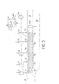
- the main axis 1 is represented diagrammatically at the level of the control airlock 10.
- This control airlock can be cut into successive slices T1, T2, T3, T4, the number of which has been limited to four on figure for convenience of representation.
- the approach link of a corresponding critical crossroads is represented at 8 while the inputs of link 8 and of the different sections are controlled by lights F, F1, F2, F3, F4.
- 24 shows the limit queue length sensor at the end of the control lock. This sensor 24 which has already been described in detail (FIG.
- the display means can indicate to the driver that it is necessary for the engine of their vehicle to be restarted.
- the sensor 24 which delimits the end of the regulation airlock is influenced, a general advance of the vehicles of the different sections is controlled, so as to avoid any overflow of the queue of vehicles, beyond the end of the airlock, on a crossroads with a secondary road. This slicing occurs of course when the absorption of circulation downstream of the airlock is in deficit.
- the processor determines with precision and at each cycle, the volume of the vehicles which can be released, by successive sections.
- the airlocks of regulation can be equipped, every 40 or 50 meters approximately, of traffic lights which can be, of course , the traffic lights of the crossroads between the main axis and the secondary tracks leading to this main axis, at the level of the control airlock.
- the lights of the units not released remain red.
- a new quota of tranches is released and the vehicles thus authorized to progress no longer stop beyond the critical crossroads.
- each of the parking lots includes a counter C connected by its output 30 to the processor, so that the latter is constantly informed of the availability in parking spaces in these various parks.
- the display means make it possible to indicate to the driver of the vehicles being in control airlocks or upstream of them (display means I n ) that parking spaces S, at very limited duration, are available in the control airlock; this is only possible when the vehicle throughput that the critical passage can absorb is greater than the vehicle throughput in the control airlock and when in this airlock, no traffic lane for public transport vehicles has been set up place, as will be seen later in detail.
- the display of the availability of parking spaces is very important. Indeed, it is necessary to establish a harmonious balance between the capacity of the road network to clear traffic and the reception capacity of the center in parking spaces. This necessity leads to finding a solution to the paradox which consists in increasing accessibility to the center of an agglomeration, without increasing traffic difficulties.
- the assistance provided to public transport by the device of the invention commits the people who move to use public transport; on the other hand, it is possible to prioritize parking lots, in order to limit traffic in very dense areas. It is thus possible to define three types of parking: the first is that which is located in the center of cities for example, and which generates traffic; this type of parking satisfies the need of users who have several points to visit in the center of an agglomeration.
- a second type of parking corresponds to parks located at the immediate limit of the hyper-center, for example. These parking lots are facing the outside of the agglomeration.
- This third type of parking which was previously organized as a deterrent park, may now have a different function; Indeed, these parks can serve as regrouping points and they can be arranged so as to offer a certain number of services relating to the automobile or to users: petrol stations, rest rooms, games rooms, etc. .
- This hierarchical structure of parking makes it possible to satisfy the needs of users, without generating excessive traffic. To be effective, it is managed in real time by the device of the invention.
- Meters such as 30, in the various parking lots, allow you to know the filling rate of these parking lots.
- the information panels I which are on the main routes of penetration in a conurbation, inform motorists about the availability of the various parking lots located near these routes; when a parking lot is full, the user is informed and he can then knowingly avoid prolonging the progression towards the center of the city, knowing that he will no longer find a parking space.
- Each of the parking lots can be equipped with pollution sensors 31, comparable to the sensors 25 in FIG.
- the processor 16 of the processing unit 14 in the event that the permissible pollution threshold in the fleet is exceeded or in the event that a fire breaks out, the processor which is informed of it applies a regulation plan contained in the memory 15, which controls different fires in the manner following: the crossroads lights located downstream of the park exit, are turned green for the benefit of users leaving these parks, so that they are not slowed down and that the evacuation of the park can be done as quickly as possible. These lights are of course located on tracks where the direction of traffic is that which moves away from the place of the fire.
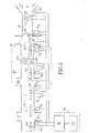
- the device of the invention has been represented, in the case where the fire plan selected in memory 15, by the processor 16 of the processing unit 14, is a plan intended for regulating the movement of public transport vehicles such as bus A in the figure.
- This plan is selected in memory when on the main axis 1 in question, one or more public transport vehicles are moving.
- the control airlock is represented at 10, the critical junction i in C, and the approach link of this critical junction is designated by the reference 8.
- the bottleneck between the approach link and the control airlock 10 is represented at 9 while non-priority cars are referenced V.
- the special control plan for public transport vehicles is selected in memory by the processor 16 when on the axis considered the maximum flow of vehicles which can absorb the critical passage C, a causes the prior establishment of a plan to increase the holding time of the vehicles in the control lock.
- the device includes sensors or beacons such as Al, A2, A3, A4, A5, A6 ..., sensitive to the presence of a public transport vehicle on the axis in question. These sensors are connected to the processor 16 of the processing system 14, and indicator means I B , make it possible to warn the drivers of moving vehicles, of the establishment of a special corridor 33, for public transport vehicles, in the control airlock 10.
- This special corridor can for example be materialized on the roadway by an interrupted light line, formed by buried lamps, the lighting of which is controlled by the processor 16.
- the means d have also been shown in the figure.
- display I S (comparable to the display means I n in FIG. 3) which make it possible to warn users of the parking possibilities in the airlock, when the special plan for public transport vehicles is not in place; these means can also indicate the waiting times in the sections of the control airlock.
- the sensors Al, ...,. A6 ...., sensitive to the presence of public transport vehicles can be constituted by radio receiving beacons, sensitive to a signal emitted by a transmitter 34, on board the vehicle A public transport.
- These sensors or beacons are arranged in the vicinity of the intersections of each of the secondary tracks 3, 36 ... with the main axis 1, so as to identify the presence and nature of public transport vehicles, as well as its speed. In fact, the distance between beacons being known, it is possible to know the speed of movement of the vehicle throughout its journey.
- the nature of the moving vehicle for example the number of the line to which this public transport vehicle belongs; can also be recognized by sensors such as A1, therefore by the processor 16, if the electrical signal emitted by the transmitter 34 includes a code corresponding to the line and to the vehicle considered.
- the processor 16 receiving the information concerning the speed and the nature of the moving vehicle, regulates this speed from the special plane selected in memory.
- the regulation lights such as 13 or 35, located at the intersections of the secondary tracks and the main axis, are of course controlled by the processor 16.
- a special light F for public transport vehicles is controlled by the processor 16 so as to turn green, a few seconds before the light 13 which frees the passage of non-priority vehicles V.
- the vehicle A of public transport crosses the approach link at the head of the peloton of the other V vehicles, which remain slightly waiting at this intersection.
- the sensors 18, 19, of queue lengths located near the critical intersection C in the approach link 8.
- the various special sensors for public transport vehicles operate, as well as the regulation lights, upstream of the regulation airlock 10, in this airlock, as well as in the approach link 8.
- the sensor A1 is made aware by the radio signals of the transmitter 34 on board the bus A.
- a signal sensor output informs processor 16 of the arrival of the bus; if the bus is on time or late on the scheduled time and if the light 35 at this intersection is red, the processor controls the passage of this light to green.
- the processor does not intervene in the regulation plan selected in memory.
- the control plan selected in memory for the various public transport vehicles includes the timetable for the passage of the various public transport vehicles, at the various intersections of the axis considered.
- the processor 16 controls upstream of this intersection, the application of the normal fire plan which was in progress before the arrival of the bus at this intersection, the one that traffic has required in the meantime.
- the restoration of the previous normal light plans is carried out as soon as the bus arrives at the height of the receiving beacon A2, made aware of the signals emitted by the transmitter 34; this tag informs the processor 16 of the arrival of the bus at its height at this instant, the prior light plan is therefore restored upstream of the tag A2.
- the clock in the processor which is not shown in the figure, can be synchronized when the bus starts at the head of the line.
- the regulation of its speed can be carried out in the manner indicated above, either by advancing or by not modifying the switching time to green.
- various lights encountered by the bus upstream of the control lock can be completed by a receiver, not shown in the figure, which allows, by means of an acknowledgment signal delivered by the beacon, to stop the transmission of the signals produced by the transmitter on board.
- This tag can itself include a transmitter, not shown in the figure, it can also include a device for recording and storing the coded signals received.
- the processor 16 cyclically examines the information delivered by the various sensors of the device. This information can also be stored over a longer period in the memory 15 of the processing system 14; they can then be used, as will be seen below in detail, for statistical purposes. Most of the information, however, is used in real time; this is particularly the case with information which makes it possible to determine whether the car L is ahead or behind the scheduled time.
- Display means as shown in I B , can be arranged on the route considered and in particular at the compulsory passenger loading stops, to inform the driver of each public transport vehicle, on his advance or on his delay. so that at each stop, the driver waits or leaves, depending on the planned control plan.
- the display means I B warn the driver of the presence of a special corridor for public transport vehicles, in the airlock; at the intersection of the secondary track 36 and the main axis 1, the beacon A 3 is sensitized by the signals emitted by the on-board transmitter; it informs the processor 16 that the light 37 must be green if the bus is late on the scheduled timetable and that this light can remain red if the bus is ahead of the scheduled timetable.
- the bus arrives in the corridor: special from the control airlock 10, so as to travel through this sound without being disturbed by vehicles V, during busy traffic periods.
- the circulation corridor lation is a "retractable" corridor which is only established during busy traffic periods, so as to encourage the progression of public transport vehicles.
- the display means I S in the control lock in addition to the display of the information previously cited, can also display, for the use of bus drivers, information of the same type as that displayed by the means I B.
- the processor when the bus reaches the level of the beacon A4, the processor is informed and establishes upstream of the crossroads between the secondary track 36 and the main axis 1, the previous light plan; the processor informed of the passage of the bus at the level of the beacon A4 can also control the light 38, which is for example here a light intended for the passage of the pedestrians at 39, so that when the bus arrives, this light passes to green if it was not already.
- the beacon A5 is made aware when the bus passes at its height ; the processor 16 informed of this passage will command a special light F, for public transport vehicles, so that this special light turns green a few moments before the light 13 intended for the other vehicles V, so that the bus engages in the approach link before all other V vehicles; the bus therefore travels through link 8, at the head of the group of non-priority vehicles V.
- the processor 16 is informed, it restores the normal light plan upstream of the link d 'approach.
- the processor 16 validates the sensor 18 as a queue, in the same way as the sensor 19.
- the processor 16 informed, thanks to the sensors queue length 18, 19, the length of the queues at the traffic light 40, near the critical intersection C acts accordingly at the control lock. If the queue goes up to the sensor 18, the initial fire plan is modified and the green time of the light 13 is reduced. If this queue goes back to sensor 19, the initial light plan undergoes a more significant modification at the level of the control airlock, so that the light 13 is red rather than expected, so that fewer vehicles are admitted into the approach link and do not thus hamper the progress of the bus.
- the establishment of retractable corridors 33 is an important aspect of the invention.
- the corridors reserved for public transport are only really necessary for a few hours a week. For 22 to 23 hours a day, these corridors would be an unnecessary constraint for residents; they would impede traffic and, as we saw above, this space can possibly be reserved for parking spaces, when the circulation in the airlock is fluid and that no restraint is necessary because all the vehicles are absorbed by the critical intersection C.
- This special corridor is therefore put in place as soon as the queue length sensors 18, 19 and the counter 17 provide the processor 16 with information showing that the flow of the critical intersection is become loss-making.
- the device of the invention comprises when this device is involved in regulating the movement of emergency vehicles such as ambulances or fire engines referenced VU in the figure. It is assumed that the emergency cars considered have to travel part of the main axis 1, to get from the emergency center P (a fire station for example) to the place S of a disaster.
- the device in this case, further comprises means 41, connected to the processor 16, so that the latter selects in memory a special fire timing plan for emergency vehicles and corresponding to the route that the emergency vehicles will have to take the road to get from the P rescue center to the S location of the disaster.
- These path selection means can be constituted in a known manner by memory elements containing information relating to the path which the emergency vehicles must take.
- the device also includes, at the exit from the rescue center and at the intersections of secondary roads with the main axis 1 of sensors Pl, P2, P3, ...., P7 etc ..., sensitive to the presence of emergency vehicles; these sensors, as in the case of public transport vehicles, are constituted by radio receivers, sensitive to the signals emitted by a transmitter E on board each of the emergency vehicles VU.
- the sensors Pl .... P7 can be associated with a transmitter while the transmitter on board VU vehicles can be associated with a receiver, so that when an emergency vehicle has passed by a sensor, the transmitter associated with this sensor causes the emission of the transmitter on board the VU vehicle to stop.
- a counter 42 connected to the processor 16, counts the number of emergency vehicles leaving this center.
- the sensor P1 informs the processor thereof; it controls the greening of all the lights located near the emergency center on route 1.
- the sensors such as P2 inform the processor 16 of this passage; the processor then establishes the fire plan initially in progress upstream of this crossroads.
- the fire plan which is selected in memory by the processor 16 makes it possible to control the lights so that on the chosen route, these lights are set to green, this is that is to say, clear the crossing of crossroads, ahead of the arrival of each emergency vehicle.
- This advance obviously depends on the predetermined speed at which the emergency vehicles must travel on the route. So for example, if when it gets to the level sensor P2, the emergency vehicle VU is late on its schedule, the light 43 will be green but also the light 44 and perhaps depending on the importance of the advance, the light 45.
- the special plan will not be modified. It is possible that one of the vehicles, for whatever reason, leaves the chosen route to take a secondary route, as indicated by arrow 46.
- the processor orders the reestablishment of the previous fire plan, over the entire axis 1. In fact, after this time delay, the processor considers that the emergency vehicles have left the main route chosen at the start.
- the device makes it possible to provide very effective assistance in the movement of emergency vehicles such as fire, police, ambulance vehicles, etc.
- emergency vehicles such as fire, police, ambulance vehicles, etc.
- the device and, in particular the transmitter on board each vehicle as well as the special sensors throughout the route allow the processor to modify the light plan so that vehicles are not slowed down.
- the previous traffic light plan is restored upstream of each crossroads, after the last emergency vehicle has passed at this crossroads.
- the discomfort for the circulation of non-priority vehicles is very low.
- Sensors sensitive to emergency vehicles which act in the event that a predetermined route has been established from the vehicles of the emergency center, can also intervene when an emergency vehicle has not selected a particular route.
- the emergency vehicles also include an on-board transmitter capable of sensitizing the sensors which then deliver information to the processor, so that the latter controls the change to green of the light located near this sensor.
- the device further comprises a central processing and control system PC, capable of exchanging information with the systems 14 to 14b, 14c, etc. of zone processing, comparable to the system 14 described above and each linked to the different sensors, meters, and regulation lights for different areas of the agglomeration.
- the central system PC can optionally be connected to a display system 47, to a printer 48 and to data input means 49.
- the memory associated with this central system is shown at 50.
- This central system allows, for example, to obtain a global visualization of the traffic in the different zones, in order to intervene in the event that interactions between zones occur; it also makes it possible to take overall decisions when an alarm is triggered, for example as a result of exceeding a determined pollution threshold in one or more zones; it also allows, in the event of a fire, to choose the most suitable emergency center for rapid intervention, etc.
- this central system can allow statistical studies on traffic and in particular on the speed of movement of vehicles in the different zones, on the pollution rates reached during specific periods, etc ...
- the regulation lights of the system which has just been described can possibly be linked to autonomous time delay systems, capable of regulating the timing of these lights, for example in the event of a system failure to which this light is connected.
- the device of the invention also applies to the real-time simulation of motor vehicle traffic, according to predetermined parameters.
- This applicat: of the device of the invention is very important. Indeed, many simulators have been built to test traffic control plans; most of these simulators use mathematical models. Unfortunately, these models do not take into account urban realities and, most of the results obtained are unusable.
- the device of the invention can be used as a simulator to find out, for example, the behavior of a road network, in the face of a fortuitous event or a planned decision. This is the case, for example, when it is necessary to build a parking lot in an area. We know that in this case, this fleet generates at certain times a certain flow of vehicles on a given axis.
- the device clearly appears to mediate the regulation of interactions between the urban environment and traffic. Indeed, if one of the parameters relating to transport is modified, this results in a certain number of effects on the urban environment, on the living environment, on the economy itself. The role of the device therefore goes far beyond regulating traffic.
- the device which has just been described makes it possible to achieve the goals mentioned above: it makes it possible to avoid traffic jams, to ensure the comfort of the population and the users of vehicles on the move, to avoid exceeding pollution thresholds harmful to the human organism, ensuring significant energy savings, increasing the safety of users of moving vehicles, increasing the speed of movement of public transport vehicles and vehicles emergency, to obtain by simulation an exact image of the consequences entailed by the modification of parameters related to traffic as well as to the comfort of the population.
- This device can be an important tool for research and in particular for medical research which often needs to carry out statistical studies. These statistical studies can be, for example, the epidemiology study, depending on different parameters related to circulation.
Landscapes
- Physics & Mathematics (AREA)
- General Physics & Mathematics (AREA)
- Traffic Control Systems (AREA)
Applications Claiming Priority (2)
| Application Number | Priority Date | Filing Date | Title |
|---|---|---|---|
| FR7912912A FR2457529A1 (fr) | 1979-05-21 | 1979-05-21 | Procede de regulation de circulation de vehicules, dispositif pour la mise en oeuvre de ce procede et application de ce dispositif a la simulation de trafic |
| FR7912912 | 1979-05-21 |
Publications (1)
| Publication Number | Publication Date |
|---|---|
| EP0019559A1 true EP0019559A1 (fr) | 1980-11-26 |
Family
ID=9225699
Family Applications (1)
| Application Number | Title | Priority Date | Filing Date |
|---|---|---|---|
| EP80400700A Ceased EP0019559A1 (fr) | 1979-05-21 | 1980-05-20 | Procédé de régulation de circulation de véhicules, dispositif pour la mise en oeuvre de ce procédé et application de ce dispositif à la simulation de trafic |
Country Status (4)
| Country | Link |
|---|---|
| EP (1) | EP0019559A1 (enExample) |
| JP (1) | JPS56500548A (enExample) |
| FR (1) | FR2457529A1 (enExample) |
| WO (1) | WO1980002616A1 (enExample) |
Cited By (4)
| Publication number | Priority date | Publication date | Assignee | Title |
|---|---|---|---|---|
| EP0681277A3 (de) * | 1994-05-04 | 1997-05-14 | Siemens Ag | Verfahren zur laufenden Messung der aktuellen Verkehrsströme an einem Verkehrsknoten. |
| GB2320122A (en) * | 1996-12-07 | 1998-06-10 | Stephen John Adams | A rapid flow traffic system |
| WO1999003082A3 (de) * | 1997-07-09 | 1999-04-01 | Siemens Ag | Verfahren und vorrichtung zur verkehrsabhängigen steuerung von lichtsignalanlagen |
| AU2005100125B4 (en) * | 2005-02-11 | 2006-11-30 | Mojarrabi, Bahram Mr | Scale free network of urban traffic |
Families Citing this family (1)
| Publication number | Priority date | Publication date | Assignee | Title |
|---|---|---|---|---|
| CN114530044B (zh) * | 2022-02-24 | 2023-08-01 | 支付宝(杭州)信息技术有限公司 | 车辆行驶调度处理方法及装置 |
-
1979
- 1979-05-21 FR FR7912912A patent/FR2457529A1/fr active Granted
-
1980
- 1980-05-20 WO PCT/FR1980/000082 patent/WO1980002616A1/fr not_active Ceased
- 1980-05-20 JP JP50108980A patent/JPS56500548A/ja active Pending
- 1980-05-20 EP EP80400700A patent/EP0019559A1/fr not_active Ceased
Non-Patent Citations (3)
| Title |
|---|
| INSTITUTION OF ELECTRICAL ENGINEERS, Advances in Computer Control, Bristol Convention, 11-14 avril 1967, LONDRES (GB), CODD: "Area traffic control", C 18, pages 1-19. * |
| INSTITUTION OF ELECTRICAL ENGINEERS, Advances in Computer Control. Bristol Convention, 11-14 avril 1967, LONDRES (GB), WHITE: "Wide area control of traffic by computer", C 13, pages 1-9. * |
| SIEMENS ZEITSCHRIFT, vol. 42, no. 5, mai 1968, ERLANGEN (DE), RUHNKE: "Gewinnung und Verarbeitung von Verkehrsdaten f}r die verkehrsabh{ngige Signalplanauswahl in Hamburg", pages 372-380. * |
Cited By (4)
| Publication number | Priority date | Publication date | Assignee | Title |
|---|---|---|---|---|
| EP0681277A3 (de) * | 1994-05-04 | 1997-05-14 | Siemens Ag | Verfahren zur laufenden Messung der aktuellen Verkehrsströme an einem Verkehrsknoten. |
| GB2320122A (en) * | 1996-12-07 | 1998-06-10 | Stephen John Adams | A rapid flow traffic system |
| WO1999003082A3 (de) * | 1997-07-09 | 1999-04-01 | Siemens Ag | Verfahren und vorrichtung zur verkehrsabhängigen steuerung von lichtsignalanlagen |
| AU2005100125B4 (en) * | 2005-02-11 | 2006-11-30 | Mojarrabi, Bahram Mr | Scale free network of urban traffic |
Also Published As
| Publication number | Publication date |
|---|---|
| WO1980002616A1 (fr) | 1980-11-27 |
| FR2457529B1 (enExample) | 1982-11-12 |
| FR2457529A1 (fr) | 1980-12-19 |
| JPS56500548A (enExample) | 1981-04-23 |
Similar Documents
| Publication | Publication Date | Title |
|---|---|---|
| CA2736080C (fr) | Procede de gestion de la circulation de vehicules sur un reseau ferroviaire et systeme associe | |
| US6320515B1 (en) | Method and equipment for motorway control | |
| EP1496413B1 (fr) | Système d'aide à la commande de la décélération d'un aéronef roulant sur le sol | |
| WO2020177767A1 (zh) | 基于电子地图的交通和旅行信息服务系统及方法 | |
| CA2581401C (fr) | Procede de gestion du freinage d'un aeronef par prevision de son deplacement sur la plateforme aeroportuaire | |
| CN109285373A (zh) | 一种面向整体道路网的智能网联交通系统 | |
| EP3095625B1 (fr) | Dispositif de dépollution d'air à stratégie de dépollution définie en fonction de l'itinéraire prévu d'un véhicule | |
| CN110969845B (zh) | 一种基于车路协同的智能车速控制方法及系统 | |
| CN113345253B (zh) | 车流阵列与信号协同控制系统 | |
| CN109615887A (zh) | 智慧交通网络系统信号指引方法 | |
| FR2895726A1 (fr) | Systeme et procede d'assistance au freinage d'un aeronef sur une piste d'atterrissage | |
| FR3106558A1 (fr) | Système et procédé d’optimisation des opérations de trains circulant le long d’une ligne ferroviaire | |
| US20210171040A1 (en) | Operating a Control Device of a Motor Vehicle in Order to Predict a Next Stopping Procedure | |
| EP0019559A1 (fr) | Procédé de régulation de circulation de véhicules, dispositif pour la mise en oeuvre de ce procédé et application de ce dispositif à la simulation de trafic | |
| CA2535267C (fr) | Procede et systeme d'aide a la circulation des trains-travaux | |
| FR2556864A1 (fr) | Systeme de surveillance de l'exploitation d'une ligne comportant une pluralite de stations, equipement de station et afficheur pour ce systeme. | |
| JP4521230B2 (ja) | 路面電車の運行支援装置 | |
| EP1834316B1 (fr) | Dispositif et procédé de gestion de parking | |
| FR2663599A1 (fr) | Systeme de transport automatique et rapide a trafic optimise. | |
| BE1027884A1 (fr) | Système de sécurisation de voies ferroviaires de maintenance | |
| CN117789493B (zh) | 一种交通控制系统及交通控制方法 | |
| FR3137641A1 (fr) | Procede d’optimisation de la consommation energetique d’un vehicule | |
| WO2024218000A1 (fr) | Systeme de regulation du trafic routier au moyen d'un systeme d'information par animations lumineuses | |
| CN110211368A (zh) | 一种车辆派遣方法和系统 | |
| EP3608198B1 (fr) | Procédé de régulation du flux des individus entrant et sortant d'une enceinte, système de signalisation associé et voiture de véhicule ferroviaire équipée d'un tel système |
Legal Events
| Date | Code | Title | Description |
|---|---|---|---|
| PUAI | Public reference made under article 153(3) epc to a published international application that has entered the european phase |
Free format text: ORIGINAL CODE: 0009012 |
|
| AK | Designated contracting states |
Designated state(s): AT BE CH DE GB IT LU NL SE |
|
| 17P | Request for examination filed |
Effective date: 19810327 |
|
| STAA | Information on the status of an ep patent application or granted ep patent |
Free format text: STATUS: THE APPLICATION HAS BEEN REFUSED |
|
| 18R | Application refused |
Effective date: 19870810 |
|
| RIN1 | Information on inventor provided before grant (corrected) |
Inventor name: FRANCERIES, CHRISTIAN |