EP0019553B1 - Autonomes Gerät zur automatischen Wahl mittels eines Vermittlungsnetzes für ein Datenverarbeitungssystem - Google Patents
Autonomes Gerät zur automatischen Wahl mittels eines Vermittlungsnetzes für ein Datenverarbeitungssystem Download PDFInfo
- Publication number
- EP0019553B1 EP0019553B1 EP80400683A EP80400683A EP0019553B1 EP 0019553 B1 EP0019553 B1 EP 0019553B1 EP 80400683 A EP80400683 A EP 80400683A EP 80400683 A EP80400683 A EP 80400683A EP 0019553 B1 EP0019553 B1 EP 0019553B1
- Authority
- EP
- European Patent Office
- Prior art keywords
- circuit
- connector
- junction
- calling unit
- control signal
- Prior art date
- Legal status (The legal status is an assumption and is not a legal conclusion. Google has not performed a legal analysis and makes no representation as to the accuracy of the status listed.)
- Expired
Links
- 230000005540 biological transmission Effects 0.000 claims description 41
- 230000015654 memory Effects 0.000 claims description 12
- 238000004891 communication Methods 0.000 claims description 3
- 230000008054 signal transmission Effects 0.000 claims 7
- 230000006978 adaptation Effects 0.000 description 19
- 238000006677 Appel reaction Methods 0.000 description 12
- 230000006870 function Effects 0.000 description 11
- 230000008878 coupling Effects 0.000 description 10
- 238000010168 coupling process Methods 0.000 description 10
- 238000005859 coupling reaction Methods 0.000 description 10
- 238000010586 diagram Methods 0.000 description 8
- 238000001514 detection method Methods 0.000 description 7
- 238000005520 cutting process Methods 0.000 description 2
- 238000005304 joining Methods 0.000 description 2
- 230000009467 reduction Effects 0.000 description 2
- 241001644893 Entandrophragma utile Species 0.000 description 1
- 238000010276 construction Methods 0.000 description 1
- 230000002950 deficient Effects 0.000 description 1
- 230000008034 disappearance Effects 0.000 description 1
- 230000010365 information processing Effects 0.000 description 1
- 238000004519 manufacturing process Methods 0.000 description 1
- 238000000034 method Methods 0.000 description 1
- 238000012544 monitoring process Methods 0.000 description 1
- 230000008520 organization Effects 0.000 description 1
- 238000011084 recovery Methods 0.000 description 1
- 230000004044 response Effects 0.000 description 1
- 230000033764 rhythmic process Effects 0.000 description 1
- 230000001360 synchronised effect Effects 0.000 description 1
- 238000010200 validation analysis Methods 0.000 description 1
Images


Classifications
-
- H—ELECTRICITY
- H04—ELECTRIC COMMUNICATION TECHNIQUE
- H04M—TELEPHONIC COMMUNICATION
- H04M1/00—Substation equipment, e.g. for use by subscribers
- H04M1/26—Devices for calling a subscriber
- H04M1/27—Devices whereby a plurality of signals may be stored simultaneously
- H04M1/274—Devices whereby a plurality of signals may be stored simultaneously with provision for storing more than one subscriber number at a time, e.g. using toothed disc
- H04M1/2745—Devices whereby a plurality of signals may be stored simultaneously with provision for storing more than one subscriber number at a time, e.g. using toothed disc using static electronic memories, e.g. chips
- H04M1/27495—Devices whereby a plurality of signals may be stored simultaneously with provision for storing more than one subscriber number at a time, e.g. using toothed disc using static electronic memories, e.g. chips implemented by means of discrete electronic components, i.e. neither programmable nor microprocessor-controlled
Definitions
- the invention relates to a stand-alone automatic call device intended for connecting a computer and data transmission equipment connected over a switched telephone network.
- Automatic call equipment already exists.
- the Applicant sells "automatic call equipment" which automatically ensures the direct communication of two data transmission equipment via the switched network.
- Such equipment is intended to be connected to a computer on the one hand and to a modulator-demodulator on the other hand.
- This equipment is connected to the computer on the one hand by a data transmission junction and on the other hand by a command signal junction.
- the automatic call equipment has no call management circuit. All management operations are carried out inside the computer itself, through its own circuits, so that a certain workload is experienced by the computer itself.
- such automatic calling equipment allows connection to only one line of the switched network.
- U.S. Patent No. 4,125,872 describes a dial adaptation circuit for cooperating with a computer that is to be coupled to telephone lines. This circuit leaves part of the workload to the computer, in particular the control of the passage to particular subroutines and the return to numbering subroutines.
- U.S. Patent No. 4,086,434 describes a system controlled by a microprocessor and capable of performing calling functions. This system considered does not relate to the field of the invention since there is no computer which requests connection to subscribers nor a circuit specifically responsible for managing calls.
- Patent of the United States of America No. 3299210 describes an apparatus for connecting a computer to telephone lines of the type considered according to the invention.
- This device given its internal architecture, does not allow simultaneous calls on multiple lines. This characteristic is however very important in the case of computers which can exchange very little data with a particular interlocutor and therefore impose a significant load of call management.
- the invention relates to a stand-alone automatic calling device intended to be placed between a computer and several telephone lines.
- all the management functions specific to automatic call operations are executed by a microprocessor incorporated in a logic circuit of the automatic call device.
- the workload necessary for the management of automatic calls on several telephone lines is fully supported by the automatic call device, and the latter only exchanges data directly passing with the computer.
- call units which may be of the type of known automatic call equipment, and on the other hand by order signals, intended to designate the references of the stations called.
- the automatic calling device ensures all management, in particular the respect of the various constraints indicated previously. Thanks to this construction, it can simultaneously make several calls on several lines.
- Each multiplexing and adaptation circuit is advantageously connected to a maximum of four call units by four junctions for transmitting order signals.
- An example of an apparatus manages eight lines and comprises two multiplexing and adaptation circuits.
- Each call unit advantageously comprises a circuit for adaptation to each of the first and second data transmission junctions, a circuit for adaptation to the second junction of command signals, a circuit for detecting different tones in particular, a circuit numbering and transmission, management, synchronization and timing circuits.
- These latter transmission, management, synchronization and timing circuits are advantageously in the form of a microprocessor, provided with the usual associated components.
- the adaptation, detection and numbering circuits are arranged on a first hardware support such as a circuit card, and that the other transmission, management and synchronization circuits. and timing devices are placed on the same hardware circuit as the management circuit of the call management logic circuit, the two hardware supports being connected by a junction for transmitting order signals.
- the microprocessor of the management circuit and that of the transmission, management, synchronization and timing circuits can form only one component.
- the apparatus according to the invention has very significant advantages. Indeed, until now, has only had equipment allowing the joining of lines only at the expense of the workload of the associated computer. Of course, the management operations necessary for such automatic calls have also already been carried out using microprocessors, but only in couplers specific to this or that type of computer. Thus, until now, the use of the automatic call function in data processing systems has required the production each time of a suitable coupler that particular type of computer considered. We know that the study costs of such specialized couplers are extremely high and consequently the automatic call function has not been developed as much as it could have been. On the contrary, the apparatus according to the invention gives very great flexibility since it can be connected to any type of computer, the connections being of standardized types used almost universally in the industry of computers.
- junctions made between the computer and the autonomous device according to the invention are junctions of universal application, designated by the reference J 100 in the recommendations of the CCITT advisory committee.
- the number of lines that can be managed by the device according to the invention can be extended at will, depending on the importance of the system of information processing.
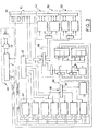
- Fig. 1 generally shows the autonomous automatic calling device according to the invention. This is intended to be mounted on the one hand between a computer, not shown but which would be on the left in fig.1, and modulator-demodulators 14, connected to telephone lines 12 allowing connection to remote equipment data transmission, for example terminals.
- the autonomous device 10 essentially comprises one or more automatic call units 16 and a logic circuit 18 for call management. Each automatic call unit 16 is connected to a modulator-demodulator 14 by means of a junction 22 for transmitting data, arriving, at the output of the device according to the invention, at a connector 20.
- the unit 16 is also connected to a connector 24 by a junction 26 for data transmission.
- the two junctions 22 and 26 are advantageously of the J 100 type, in accordance with the recommendations of the CCITT committee. Junctions 22 and 26 provide only the transmission of data originating from the computer and intended for the terminals or coming from the terminals and intended for the computer.
- a junction 28 which is advantageously also of a standardized or recommended type, for example of the J 200 type of the CCITT committee, provides the link between the call units 16 and the logic circuit 18 for call management, separately. It should be noted that each junction 28 transmits only order signals and no data signal. Each junction 28 can also be doubled by a specific line allowing the transmission of particular signals between the logic circuit 18 and the call unit 16, indicating in particular the failure of a call due to the disappearance of a number d call having given rise to an incident, for example of a type which does not satisfy the constraints indicated above.
- the call units 16 are also connected to terminals 32, 34, 36.
- Terminal 32 is intended to allow a direct telephone link between the modulator-demodulator 14 and the associated call unit 16.
- the connector 34 is intended to allow direct connection of a telephone handset 38, which can thus be indirectly connected to line 12.
- the unit 16 is also connected, optionally, to an external circuit 40 which, under the control of the logic circuit 18, transmits messages.
- the circuit 18 controls the transmission to this subscriber of a message recorded in the apparatus 40 and indicating the origin and the cause of the error so that this disturbed subscriber is reassured.
- Fig. 2 is a slightly more detailed block diagram of the logic circuit 18 for call management.
- This essentially comprises a management circuit proper, identified by the reference 42, and one, two, three, ... circuits 44 for multiplexing and adaptation.
- the circuit 42 shown in more detail in FIG. 3, generally comprises a microprocessor 46, for example a microprocessor of the 6800 series from Motorola, for example of the 6802 type.
- the circuit 42 also includes memories 48, a circuit 52 for coupling to a synchronous control line and circuits 54 and 56 for coupling to circuits 44 for multiplexing and adaptation.
- These circuits 44 are described in more detail with reference to FIG. 4.
- an omnibus line 50 allowing an extension of the memories, and the line 60, connected to the coupling circuit 52, joins the connector 30 shown in FIG. 1.
- FIG. 3 shows in more detail the circuit 42 for managing the logic circuit 18. It is recognized in FIG. the microprocessor 46, associated with a clock and a recovery command, the memories 48, the coupling circuit 52, the coupling circuits 54, 56 and the asynchronous line 60.
- FIG. 3 indicates the relationship between the different elements, and the reference 62 designates a programmable address field decoding memory.
- the memory 48 in fact comprises reprogrammable memories 64 and direct access memories 66 associated with a decoder 67.
- the reference 68 represents a conventional rhythm circuit.
- References 70 and 72 designate data and address bus lines respectively.
- circuit 52 intended to be connected to the asynchronous line constitutes a series adaptation circuit while the coupling circuits 54 and 56 intended to be connected to the multiplexing and adaptation circuits 44 provide connections of parallel type .
- the entire circuit of fig. is preferably formed on a single circuit board, the connections being provided by the coupling circuits 52, 54, 56, 60 formed at the backplane or on the front face.
- Fig. 4 is a block diagram of a multiplexing and adaptation circuit, identified by the reference 44 in FIG. 2.
- This circuit is advantageously formed on a single card and is intended for managing exchanges on four telephone lines. To this end, it includes a single circuit 74 for decoding an address, intended to transmit signals to four parallel circuits, only one of which is shown in FIG. 4, the lines ending in dashed lines being intended to ensure the connections to the three other similar circuits connected in parallel.
- the reference 76 designates a data memory and the reference 78 a buffer circuit.
- References 80 and 82 respectively represent transmission and reception adaptation circuits.
- Lines 84 represent the aforementioned junction J 200 which reaches a call unit 16.
- the circuit 74 receives the signals from the coupling circuit 56, and the lines 86 ensure the transmission of information between the coupling circuit 54 of the management circuit of FIG. 3 and the specific circuits 76 and 78 of the four line circuits.
- Fig. 5 is a block diagram of an automatic call unit according to a variant of the invention.
- the unit 16 briefly described with reference to FIG. 1 is a known type circuit board, presented in the form of a fully wired plug-in printed circuit board.
- a certain number of management operations are carried out at the level of the automatic call unit.
- Fig. shows the general architecture of such a variant of automatic call unit, generally identified by the reference 88.
- the line shown on the left is intended to join the connector 32.
- Circuit 90 simply represents a line matching circuit.
- circuits 92, 94 and 96 which are respectively intended for the detection of the call pick-up signal of the called number, for the detection of the invitation and pursuit tones, and for the detection of the tone identifying an automatic call subscriber (signal at 2100 Hz).
- These three circuits therefore fulfill detection functions on the basis of the information they receive via the line adaptation circuit 90.
- the information they detect reaches a line management circuit 98.
- the latter also exchanges information with a circuit 100 intended to transmit, via the adaptation circuit 90, a signal at 1300 Hz.
- the line management circuit 98 controls circuits 102 and 104 intended for controlling the call, each of the circuits corresponding to one of the calling techniques, that is to say to cutting the line current or to the multi-frequency call. Calls are therefore possible with both types of circuit in switched networks.
- the line management circuit 98 also exchanges information with a general synchronization and timing management circuit 106. This circuit is connected on the one hand to a circuit 108 for monitoring the operation of the circuit 100 for adapting to the junctions J 100 22 and 26 and on the other hand to a circuit 112 for managing the exchanges carried out by the junction J 200 28, using an adaptation circuit 114.
- each call unit 88 When the workload of the call unit is particularly high, it is advantageous for each call unit 88 to have its own microprocessor whereas, on the contrary, for infrequent operations or a reduced work load, it is preferable that the operations devolved to circuits 98, 100, 106, 108 and 112 are executed by the microprocessor 46 of circuit 42.
- circuit 88 relates to a separate card of components 90, 92, 94, 96, 102, 104, 110 and 114 , and an additional junction is made between these different components and the microprocessor 46.
- the call unit 88 has great advantages. First, it allows a reduction in the hardware used because the microprocessor takes over most of the logic functions which, in known circuits, are implemented by discrete components. This reduction in volume also allows the implementation of additional functions which the known circuits cannot fulfill, for example the execution of a numbering sequence by cutting the line current, or the execution a dialing sequence by sending multi-frequency codes.
- the invention relates to an autonomous automatic call device which completely separates the operations of exchanging data and exchanging orders and information other than data, and which is also responsible for all the operations of management. It should be noted that, when these operations must be programmed at the level of the computer of the data processing system, the programming work is considerable since these automatic call functions overlap more or less with the other functions. On the contrary, in the apparatus according to the invention, all of these functions are separate and it suffices for the computer to transmit its orders, that is to say the telephone numbers of the lines to which it must transmit data.
Landscapes
- Engineering & Computer Science (AREA)
- Physics & Mathematics (AREA)
- Computer Hardware Design (AREA)
- Discrete Mathematics (AREA)
- General Physics & Mathematics (AREA)
- Microelectronics & Electronic Packaging (AREA)
- Signal Processing (AREA)
- Financial Or Insurance-Related Operations Such As Payment And Settlement (AREA)
- Exchange Systems With Centralized Control (AREA)
- Communication Control (AREA)
Claims (10)
Applications Claiming Priority (2)
| Application Number | Priority Date | Filing Date | Title |
|---|---|---|---|
| FR7912661 | 1979-05-18 | ||
| FR7912661A FR2457046A1 (fr) | 1979-05-18 | 1979-05-18 | Appareil autonome d'appel automatique par reseau commute pour systeme de traitement d'informations |
Publications (2)
| Publication Number | Publication Date |
|---|---|
| EP0019553A1 EP0019553A1 (de) | 1980-11-26 |
| EP0019553B1 true EP0019553B1 (de) | 1983-05-04 |
Family
ID=9225616
Family Applications (1)
| Application Number | Title | Priority Date | Filing Date |
|---|---|---|---|
| EP80400683A Expired EP0019553B1 (de) | 1979-05-18 | 1980-05-16 | Autonomes Gerät zur automatischen Wahl mittels eines Vermittlungsnetzes für ein Datenverarbeitungssystem |
Country Status (3)
| Country | Link |
|---|---|
| EP (1) | EP0019553B1 (de) |
| DE (1) | DE3062947D1 (de) |
| FR (1) | FR2457046A1 (de) |
Families Citing this family (1)
| Publication number | Priority date | Publication date | Assignee | Title |
|---|---|---|---|---|
| JPS612462A (ja) * | 1984-06-15 | 1986-01-08 | Oki Electric Ind Co Ltd | オ−トダイアル方式 |
Family Cites Families (3)
| Publication number | Priority date | Publication date | Assignee | Title |
|---|---|---|---|---|
| US3299210A (en) * | 1963-03-18 | 1967-01-17 | Ibm | Apparatus for connecting a multichannel data processor with a plurality of telephone lines |
| US4086434A (en) * | 1976-09-07 | 1978-04-25 | Leo P. Christiansen | Remote condition reporting system |
| US4125872A (en) * | 1977-03-31 | 1978-11-14 | Racal-Vadic, Inc. | Multiline automatic calling system adapter |
-
1979
- 1979-05-18 FR FR7912661A patent/FR2457046A1/fr active Granted
-
1980
- 1980-05-16 EP EP80400683A patent/EP0019553B1/de not_active Expired
- 1980-05-16 DE DE8080400683T patent/DE3062947D1/de not_active Expired
Also Published As
| Publication number | Publication date |
|---|---|
| DE3062947D1 (en) | 1983-06-09 |
| EP0019553A1 (de) | 1980-11-26 |
| FR2457046B1 (de) | 1982-04-02 |
| FR2457046A1 (fr) | 1980-12-12 |
Similar Documents
| Publication | Publication Date | Title |
|---|---|---|
| EP0034514B1 (de) | Digitale Zeitvielfach-Vermittlungsanlage für Leitungen mit Sprach- und Datenpaketübertragungen | |
| EP0350402B1 (de) | Personal-Computer, in den ein digitales ISDN-Teilnehmerendgerät integriert ist | |
| FR2753862A1 (fr) | Procede et systeme de communication interactive entre deux appareils telephoniques via le reseau internet | |
| EP0036807B1 (de) | Konzentrator für Kommunikationssystem zum Anschliessen mehrerer asynchroner Telematik-Terminals | |
| FR2594614A1 (fr) | Systeme de commutation de communications | |
| EP0377203B1 (de) | Empfangs- und Bearbeitungssystem für PCM-TDM-mehrwegübertragene HDLC-Rahmen, insbesondere für Datenvermittler | |
| EP0120495A1 (de) | Einrichtung zum Austausch von kodierten Nachrichten zwischen Stationen | |
| EP0019553B1 (de) | Autonomes Gerät zur automatischen Wahl mittels eines Vermittlungsnetzes für ein Datenverarbeitungssystem | |
| EP0645902B1 (de) | Satellitenanordnung für Datenübertragung zwischen Telefonvermittlungstellen, Verkehrstation und Übertragungsverfahren dafür | |
| EP1494383A1 (de) | WDM Optisches Ringnetzwerk für Signalübertragung gesichert durch Lokaler Zustandschaltung bei Erfassung einer Lokale Unterbrechung | |
| FR2812146A1 (fr) | Composants programmables et systemes pour des communications en full-duplex entre un maitre et plusieurs esclaves | |
| FR2738699A1 (fr) | Systeme de gestion des telecommunications | |
| EP0589743B1 (de) | Modulare Vorrichtung zum Koppeln und zum Multiplexen von unterschiedlichen Bussen | |
| FR2641629A1 (fr) | Procede d'adressage automatique de blocs modulaires standards et ensemble pour la mise en oeuvre de ce procede | |
| CA2370526A1 (fr) | Systeme de mise en oeuvre de services telephoniques, organe de commande d'un autocommutateur et serveur cti | |
| FR2726383A1 (fr) | Systeme de traitement d'informations comportant au moins deux processeurs | |
| EP0101377A1 (de) | Vorrichtung für die Steuerung von Dateienübertragungen zwischen Rechnern | |
| EP0720331A1 (de) | Anordnung zur Verkettung von Zwischenmodulen, insbesondere Relaisstationen und damit ausgerüstete Einrichtung | |
| FR2570233A1 (fr) | Reseau numerique asynchrone | |
| WO1999003229A1 (fr) | Dispositif interface de communication entre une installation terminale d'abonne d'un reseau externe et un reseau interne | |
| EP0091327A1 (de) | Videokonferenzsystem für mehrere Säle | |
| EP0610106A1 (de) | Signalierungsverarbeitungssystem für gemeinsame Unterstützung der Durchschaltebetriebsart in einer Telekommunikationsanlage | |
| EP0383666B1 (de) | Modulare Interface-Schaltung und Teilnehmeranordnung für ein digitales Netz | |
| EP1056298A1 (de) | Signalisierungssignalübertragungsfähigkeit | |
| CA2274723A1 (fr) | Systeme de transfert de donnees entre stations multiples |
Legal Events
| Date | Code | Title | Description |
|---|---|---|---|
| PUAI | Public reference made under article 153(3) epc to a published international application that has entered the european phase |
Free format text: ORIGINAL CODE: 0009012 |
|
| AK | Designated contracting states |
Designated state(s): BE CH DE GB IT LU NL |
|
| 17P | Request for examination filed |
Effective date: 19810525 |
|
| ITF | It: translation for a ep patent filed | ||
| GRAA | (expected) grant |
Free format text: ORIGINAL CODE: 0009210 |
|
| AK | Designated contracting states |
Designated state(s): BE CH DE GB IT LI LU NL |
|
| PG25 | Lapsed in a contracting state [announced via postgrant information from national office to epo] |
Ref country code: NL Effective date: 19830504 |
|
| PG25 | Lapsed in a contracting state [announced via postgrant information from national office to epo] |
Ref country code: LU Free format text: LAPSE BECAUSE OF NON-PAYMENT OF DUE FEES Effective date: 19830531 |
|
| REF | Corresponds to: |
Ref document number: 3062947 Country of ref document: DE Date of ref document: 19830609 |
|
| PGFP | Annual fee paid to national office [announced via postgrant information from national office to epo] |
Ref country code: LU Payment date: 19830704 Year of fee payment: 4 |
|
| NLV1 | Nl: lapsed or annulled due to failure to fulfill the requirements of art. 29p and 29m of the patents act | ||
| PLBE | No opposition filed within time limit |
Free format text: ORIGINAL CODE: 0009261 |
|
| STAA | Information on the status of an ep patent application or granted ep patent |
Free format text: STATUS: NO OPPOSITION FILED WITHIN TIME LIMIT |
|
| PGFP | Annual fee paid to national office [announced via postgrant information from national office to epo] |
Ref country code: CH Payment date: 19840416 Year of fee payment: 5 |
|
| 26N | No opposition filed | ||
| PGFP | Annual fee paid to national office [announced via postgrant information from national office to epo] |
Ref country code: BE Payment date: 19840630 Year of fee payment: 5 |
|
| PGFP | Annual fee paid to national office [announced via postgrant information from national office to epo] |
Ref country code: DE Payment date: 19840724 Year of fee payment: 5 |
|
| PG25 | Lapsed in a contracting state [announced via postgrant information from national office to epo] |
Ref country code: LI Effective date: 19870531 Ref country code: CH Effective date: 19870531 |
|
| BERE | Be: lapsed |
Owner name: TRAITEMENT DE L'INFORMATION TECHNIQUES NOUVELLES Effective date: 19870531 |
|
| REG | Reference to a national code |
Ref country code: CH Ref legal event code: PL |
|
| PG25 | Lapsed in a contracting state [announced via postgrant information from national office to epo] |
Ref country code: DE Effective date: 19880202 |
|
| GBPC | Gb: european patent ceased through non-payment of renewal fee | ||
| PG25 | Lapsed in a contracting state [announced via postgrant information from national office to epo] |
Ref country code: GB Free format text: LAPSE BECAUSE OF NON-PAYMENT OF DUE FEES Effective date: 19881118 |
|
| PG25 | Lapsed in a contracting state [announced via postgrant information from national office to epo] |
Ref country code: BE Effective date: 19890531 |