EP0019546A1 - Connecteur thermique à verrouillage quart de tour - Google Patents
Connecteur thermique à verrouillage quart de tour Download PDFInfo
- Publication number
- EP0019546A1 EP0019546A1 EP80400665A EP80400665A EP0019546A1 EP 0019546 A1 EP0019546 A1 EP 0019546A1 EP 80400665 A EP80400665 A EP 80400665A EP 80400665 A EP80400665 A EP 80400665A EP 0019546 A1 EP0019546 A1 EP 0019546A1
- Authority
- EP
- European Patent Office
- Prior art keywords
- connector
- key
- clamp
- thermal
- cheeks
- Prior art date
- Legal status (The legal status is an assumption and is not a legal conclusion. Google has not performed a legal analysis and makes no representation as to the accuracy of the status listed.)
- Withdrawn
Links
- 239000002184 metal Substances 0.000 claims abstract description 5
- 238000005096 rolling process Methods 0.000 claims description 2
- 238000009434 installation Methods 0.000 description 4
- 230000017525 heat dissipation Effects 0.000 description 3
- 238000004378 air conditioning Methods 0.000 description 1
- 238000005516 engineering process Methods 0.000 description 1
- 238000012423 maintenance Methods 0.000 description 1
- 238000004519 manufacturing process Methods 0.000 description 1
- 238000011084 recovery Methods 0.000 description 1
- 238000007493 shaping process Methods 0.000 description 1
- 239000002470 thermal conductor Substances 0.000 description 1
- XLYOFNOQVPJJNP-UHFFFAOYSA-N water Substances O XLYOFNOQVPJJNP-UHFFFAOYSA-N 0.000 description 1
Images

Classifications
-
- H—ELECTRICITY
- H05—ELECTRIC TECHNIQUES NOT OTHERWISE PROVIDED FOR
- H05K—PRINTED CIRCUITS; CASINGS OR CONSTRUCTIONAL DETAILS OF ELECTRIC APPARATUS; MANUFACTURE OF ASSEMBLAGES OF ELECTRICAL COMPONENTS
- H05K7/00—Constructional details common to different types of electric apparatus
- H05K7/20—Modifications to facilitate cooling, ventilating, or heating
- H05K7/20536—Modifications to facilitate cooling, ventilating, or heating for racks or cabinets of standardised dimensions, e.g. electronic racks for aircraft or telecommunication equipment
- H05K7/20545—Natural convection of gaseous coolant; Heat transfer by conduction from electronic boards
-
- Y—GENERAL TAGGING OF NEW TECHNOLOGICAL DEVELOPMENTS; GENERAL TAGGING OF CROSS-SECTIONAL TECHNOLOGIES SPANNING OVER SEVERAL SECTIONS OF THE IPC; TECHNICAL SUBJECTS COVERED BY FORMER USPC CROSS-REFERENCE ART COLLECTIONS [XRACs] AND DIGESTS
- Y10—TECHNICAL SUBJECTS COVERED BY FORMER USPC
- Y10T—TECHNICAL SUBJECTS COVERED BY FORMER US CLASSIFICATION
- Y10T24/00—Buckles, buttons, clasps, etc.
- Y10T24/34—Combined diverse multipart fasteners
- Y10T24/3427—Clasp
- Y10T24/3439—Plural clasps
- Y10T24/344—Resilient type clasp
- Y10T24/3441—Resilient type clasp and cam
Definitions
- the present invention relates to a thermal connector with quarter-turn locking. It finds an application in electronics.
- the present invention provides a solution to this problem by proposing a thermal connector which is effectively very simple to use, which does not hamper the electrical connections and which can even participate in the mechanical maintenance of the supports to which it is connected.
- the subject of the present invention is a thermal connector which is intended to connect a heat dissipating support to a thermal drain and which is characterized in that it is constituted by a deformable double metal clamp, each clamp being constituted by two cheeks conforming to the shape of the dissipating support for one of the pliers and that of the heat sink for the other, the connector comprising, between the pliers, a housing for a flattened operating key, this key having a rest position in which the flat exerts no force on the walls of the central housing, the cheeks of the end clamps then being moved apart and the connector unlocked, and a working position, obtained by rotating the key a quarter of a turn relative to in the rest position, the key. then move aside the walls of the central housing and tighten the cheeks of the two end clamps, the connector then being locked.
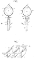
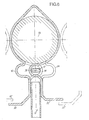
- FIGS. 1 and 2 A first embodiment of a connector according to the invention is illustrated in FIGS. 1 and 2.
- the connector shown comprises a first end clamp 2, formed by two cheeks 3 'and 3 ", and a second end clamp 4, formed by two cheeks 5' and 5", joined along an edge 6 forming dihedral.
- a housing 8 receives an operating key 10 comprising a flat.
- the cheeks 3 'and 3 "forming the lower clamp 2 are flat, as is the dissipator support 12 on which they are applied and the cheeks 5' and 5" of the upper clamp are cylindrical, like the drain 14 that they enclose.
- this device is as follows. At rest, the key is in the position shown in parts (a) of the figures and the flat part of this key is in the plane of symmetry of the assembly: no action is exerted on the walls of the housing 8. The cheeks of the two clamps are clamped neither on the dissipator support 12, nor on the drain 14. By rotation of a quarter turn of the key 10, the flat is brought into a position perpendicular to the plane of symmetry of the assembly. In this position the walls of the central housing are spaced apart, which has the effect of tightening the cheeks 3 ', 3 "on the support 12 and the cheeks 5', 5" on the drain 14.
- the connector shown has at its upper part a dihedral, the role of which is to ensure a certain elasticity, to authorize certain manufacturing tolerances on the drain as well as to compensate for any play due to the expansion of the parts.
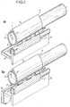
- the connector of fig. 3 is shown in perspective in part (a) and in cross section in part (b).
- the connector comprises two pairs of clamps, the first formed by the clamps 2 1 and 4 1 which are fitted respectively on a first dissipating support 12 1 and on a drain 14, and the second by the clamps 2 2 and 4 2 which are fitted on a second dissipative support 12 2 and on the same drain 14, the clamps 4 1 and 4 2 therefore forming only one.
- An operating key is provided for each part of the connector, i.e. 10 1 and 10 2 respectively .
- the two keys are in the rest position, and on part (b) the key 10 is in the locking position.
- dissipative supports 12 1 and 12 2 have at their end a bulged part which allows better tightening by the cheeks of the connector.
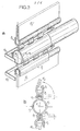
- the elements forming the connector are obtained by cutting in a strip, followed by shaping by stamping or rolling.
- these elements consist of 2D cut blades 1 , 21 1 ... 2 0 2 , 21 ..., which may be simpler.
- I1 is illustrated by the parts (b) and (c) which show, in cross section, the position of the elements making up the lower part of the connector when the associated key 10 1 is in the rest position (b) and in the position of lock (c).
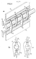
- the connector shown in fig. 5 does not differ from that of FIG. 3 only by the presence of split biconical rings 24 ', 24 "... which receive cylindrical drains 14', 14", etc ... with axes perpendicular to that of the drain 14.
- Part (a) of this figure shows the connector in perspective with, on the right, a detail of a ring 24 '; part (b) represents the connector in cross section with its upper part pinched on the support 12 2 and its lower part open.
- the connector shown in section in FIG. 6 has as originality, compared to the connectors described above, that of having fins 30 and 32 at its lower part. These fins form a baffle with the fins 32 'and 30 "of the neighboring connectors, which constitutes a means of taking up the calories released by the dissipating support 12 by taking advantage of the convection currents which reach these fins.
- the heat dissipation is The parts located in the central part of the connector are obtained by making a puncture and then stamping parts sometimes on one side, sometimes on the other, to obtain either the cheeks 34 and 36 necessary for housing the key. operation 10, ie the cheeks 38 and 40 necessary for the passage of the command, the entire metal section is therefore used in this case, which makes the thermal conductivity of the connector maximum.
- the heat sink 14 has a circular cylindrical shape only by way of example; this shape, and consequently that of the cheeks of the end clamp, could be quite different. Likewise for the shape of the clamp associated with the heat sink, which may not be flat.
- Fig. 7 shows, very schematically, a thermal drainage installation which implements the invention.
- This installation comprises thermal drains 42 connected by connectors 44 in accordance with the invention, to cards 46, supports for dissipating electronic components, these cards being embedded in a chassis 48.
- the thermal conduction flow is established from cards 46 to the drains 42 through the connectors 44, then, through the drains, to a collector not shown.
Landscapes
- Engineering & Computer Science (AREA)
- Aviation & Aerospace Engineering (AREA)
- Physics & Mathematics (AREA)
- Thermal Sciences (AREA)
- Microelectronics & Electronic Packaging (AREA)
- Connector Housings Or Holding Contact Members (AREA)
- Cooling Or The Like Of Electrical Apparatus (AREA)
Applications Claiming Priority (2)
| Application Number | Priority Date | Filing Date | Title |
|---|---|---|---|
| FR7912310A FR2457055A1 (fr) | 1979-05-15 | 1979-05-15 | Connecteur thermique a verrouillage quart de tour |
| FR7912310 | 1979-05-15 |
Publications (1)
| Publication Number | Publication Date |
|---|---|
| EP0019546A1 true EP0019546A1 (fr) | 1980-11-26 |
Family
ID=9225478
Family Applications (1)
| Application Number | Title | Priority Date | Filing Date |
|---|---|---|---|
| EP80400665A Withdrawn EP0019546A1 (fr) | 1979-05-15 | 1980-05-13 | Connecteur thermique à verrouillage quart de tour |
Country Status (4)
| Country | Link |
|---|---|
| US (1) | US4362286A (OSRAM) |
| EP (1) | EP0019546A1 (OSRAM) |
| JP (1) | JPS55153398A (OSRAM) |
| FR (1) | FR2457055A1 (OSRAM) |
Cited By (1)
| Publication number | Priority date | Publication date | Assignee | Title |
|---|---|---|---|---|
| EP0058759A3 (en) * | 1981-02-25 | 1983-07-27 | Siemens Aktiengesellschaft | Modular control apparatus |
Families Citing this family (1)
| Publication number | Priority date | Publication date | Assignee | Title |
|---|---|---|---|---|
| US5251795A (en) * | 1991-12-16 | 1993-10-12 | Bruce Jeppesen | Clip-on carrying case |
Citations (2)
| Publication number | Priority date | Publication date | Assignee | Title |
|---|---|---|---|---|
| US3268772A (en) * | 1963-03-26 | 1966-08-23 | North American Aviation Inc | Packaged electronic equipment |
| FR2210824A1 (OSRAM) * | 1972-12-18 | 1974-07-12 | Texas Instruments Inc |
Family Cites Families (3)
| Publication number | Priority date | Publication date | Assignee | Title |
|---|---|---|---|---|
| US584329A (en) * | 1897-06-15 | Bedclothes-clamp | ||
| US597511A (en) * | 1898-01-18 | Curtain-fastener | ||
| US1716928A (en) * | 1927-01-27 | 1929-06-11 | Mirkin Max | Clamp |
-
1979
- 1979-05-15 FR FR7912310A patent/FR2457055A1/fr active Granted
-
1980
- 1980-05-12 US US06/148,944 patent/US4362286A/en not_active Expired - Lifetime
- 1980-05-13 EP EP80400665A patent/EP0019546A1/fr not_active Withdrawn
- 1980-05-14 JP JP6388280A patent/JPS55153398A/ja active Pending
Patent Citations (2)
| Publication number | Priority date | Publication date | Assignee | Title |
|---|---|---|---|---|
| US3268772A (en) * | 1963-03-26 | 1966-08-23 | North American Aviation Inc | Packaged electronic equipment |
| FR2210824A1 (OSRAM) * | 1972-12-18 | 1974-07-12 | Texas Instruments Inc |
Cited By (1)
| Publication number | Priority date | Publication date | Assignee | Title |
|---|---|---|---|---|
| EP0058759A3 (en) * | 1981-02-25 | 1983-07-27 | Siemens Aktiengesellschaft | Modular control apparatus |
Also Published As
| Publication number | Publication date |
|---|---|
| FR2457055A1 (fr) | 1980-12-12 |
| US4362286A (en) | 1982-12-07 |
| JPS55153398A (en) | 1980-11-29 |
| FR2457055B1 (OSRAM) | 1984-04-13 |
Similar Documents
| Publication | Publication Date | Title |
|---|---|---|
| FR2824960A1 (fr) | Dispositif de raccordement a poussoir | |
| EP0558359A1 (fr) | Dispositif de fixation d'un composant électronique contre une paroi d'un dissipateur thermique | |
| FR2716297A3 (fr) | Connecteur électrique avec douille à force d'insertion nulle. | |
| FR2776428A1 (fr) | Connecteur electrique a plan de masse configurable et ce plan de masse | |
| FR2638772A1 (fr) | Dispositif pour retenir la neige sur une toiture en tole et toiture equipee d'un tel dispositif | |
| EP0373052A1 (fr) | Support pour ligne de transmission hyperfréquence, notamment du type triplaque | |
| EP0643446A1 (fr) | Perfectionnements aux boîtiers de connecteurs électriques | |
| EP0148051B1 (fr) | Procédé et dispositif de connexion électrique fixé de tresses sur des plages d'amenée de courant | |
| FR2989230A1 (fr) | Connecteur de bord de carte traversant et ensemble de composants | |
| EP1912287B1 (fr) | Connecteur électrique pour carte de circuit imprimé et boitier électrique étanche contenant un tel connecteur | |
| EP0019546A1 (fr) | Connecteur thermique à verrouillage quart de tour | |
| EP0026703A1 (fr) | Embase de raccordement pour circuits électriques, et circuit muni d'une telle embase | |
| EP4345577A1 (fr) | Dissipateur thermique pour carte réseau de lame de calcul | |
| FR2713877A3 (fr) | Capot de protection pour plaquettes de circuits imprimés dont le moyen de fixation se fait sans brasage, agrafage, rivetage ou autres. | |
| EP3089295A1 (fr) | Dispositif d'interconnexion électrique configuré pour établir une liaison équipotentielle entre un tronçon de chemin de câbles et un tronçon de câble électrique | |
| FR2972291A1 (fr) | Embase pour relais | |
| EP0999613A1 (fr) | Prise de connexion sur circuit imprime, comprenant une fiche et une embase | |
| WO2004030170A2 (fr) | Dispositif de fixation et de contact pour barres de bus | |
| FR2819348A1 (fr) | Connexion autodenudante a fente convergente | |
| FR2907266A1 (fr) | Dispositif de raccordement electrique notamment pour panneau solaire electrique | |
| EP2626879A1 (fr) | Embase pour relais | |
| FR2542964A1 (fr) | Dispositif de borne femelle, notamment pour circuits imprimes | |
| FR2701338A1 (fr) | Dispositif pour le raccordement de deux languettes mâles d'organes de contacts électriques. | |
| EP0967504B1 (fr) | Croisement entre un joint rond et un joint plat | |
| EP1148589B1 (fr) | Elément femelle de connexion et connecteur femelle comportant un tel élément de connexion |
Legal Events
| Date | Code | Title | Description |
|---|---|---|---|
| PUAI | Public reference made under article 153(3) epc to a published international application that has entered the european phase |
Free format text: ORIGINAL CODE: 0009012 |
|
| AK | Designated contracting states |
Designated state(s): DE GB NL SE |
|
| 17P | Request for examination filed |
Effective date: 19810430 |
|
| STAA | Information on the status of an ep patent application or granted ep patent |
Free format text: STATUS: THE APPLICATION HAS BEEN WITHDRAWN |
|
| 18W | Application withdrawn |
Withdrawal date: 19821127 |
|
| RIN1 | Information on inventor provided before grant (corrected) |
Inventor name: LE ROUZIC, JEAN Inventor name: GENTRIC, ALAIN |