EP0019522A1 - Accouplement débrayable et son application au fonctionnement d'une vanne - Google Patents
Accouplement débrayable et son application au fonctionnement d'une vanne Download PDFInfo
- Publication number
- EP0019522A1 EP0019522A1 EP19800400622 EP80400622A EP0019522A1 EP 0019522 A1 EP0019522 A1 EP 0019522A1 EP 19800400622 EP19800400622 EP 19800400622 EP 80400622 A EP80400622 A EP 80400622A EP 0019522 A1 EP0019522 A1 EP 0019522A1
- Authority
- EP
- European Patent Office
- Prior art keywords
- coupling according
- ball
- axis
- needle
- disengageable coupling
- Prior art date
- Legal status (The legal status is an assumption and is not a legal conclusion. Google has not performed a legal analysis and makes no representation as to the accuracy of the status listed.)
- Ceased
Links
- 230000008878 coupling Effects 0.000 claims description 21
- 238000010168 coupling process Methods 0.000 claims description 21
- 238000005859 coupling reaction Methods 0.000 claims description 21
- 230000005484 gravity Effects 0.000 claims description 6
- 238000010438 heat treatment Methods 0.000 claims description 2
- 230000001419 dependent effect Effects 0.000 abstract 1
- 229910000831 Steel Inorganic materials 0.000 description 3
- 239000003638 chemical reducing agent Substances 0.000 description 3
- 239000010959 steel Substances 0.000 description 3
- 230000000694 effects Effects 0.000 description 2
- 229910000760 Hardened steel Inorganic materials 0.000 description 1
- 230000005540 biological transmission Effects 0.000 description 1
- 239000004519 grease Substances 0.000 description 1
- 239000000463 material Substances 0.000 description 1
- 239000002184 metal Substances 0.000 description 1
- 238000013021 overheating Methods 0.000 description 1
- 239000007787 solid Substances 0.000 description 1
Images
Classifications
-
- F—MECHANICAL ENGINEERING; LIGHTING; HEATING; WEAPONS; BLASTING
- F16—ENGINEERING ELEMENTS AND UNITS; GENERAL MEASURES FOR PRODUCING AND MAINTAINING EFFECTIVE FUNCTIONING OF MACHINES OR INSTALLATIONS; THERMAL INSULATION IN GENERAL
- F16D—COUPLINGS FOR TRANSMITTING ROTATION; CLUTCHES; BRAKES
- F16D15/00—Clutches with wedging balls or rollers or with other wedgeable separate clutching members
-
- F—MECHANICAL ENGINEERING; LIGHTING; HEATING; WEAPONS; BLASTING
- F16—ENGINEERING ELEMENTS AND UNITS; GENERAL MEASURES FOR PRODUCING AND MAINTAINING EFFECTIVE FUNCTIONING OF MACHINES OR INSTALLATIONS; THERMAL INSULATION IN GENERAL
- F16D—COUPLINGS FOR TRANSMITTING ROTATION; CLUTCHES; BRAKES
- F16D7/00—Slip couplings, e.g. slipping on overload, for absorbing shock
- F16D7/04—Slip couplings, e.g. slipping on overload, for absorbing shock of the ratchet type
- F16D7/06—Slip couplings, e.g. slipping on overload, for absorbing shock of the ratchet type with intermediate balls or rollers
- F16D7/10—Slip couplings, e.g. slipping on overload, for absorbing shock of the ratchet type with intermediate balls or rollers moving radially between engagement and disengagement
Definitions
- the invention relates to a disengageable coupling allowing at will to progressively establish or break the connection between two successive parts of a movement transmission.
- clutch is meant the member performing the coupling of two shafts, at least one of which is in rotation, at the end of which the movement of these two shafts is brought to synchronism.
- the two parts at least one of which affects the shape of a solid of revolution, can be brought into contact under a clamping force.
- the resulting sliding friction produces on each of the shafts a torque tending to accelerate the one whose speed is initially the lowest, thus playing for him the role of the driving torque, and to oppose the movement of the other, for which it acts in resistant couple.
- the disengageable coupling according to the invention has, more particularly, the purpose of connecting a mixing valve to a servomotor by means of a reducer, but which can also be operated manually.
- the speed at the outlet of the reducer is very low, 3 rev / hour in a nonlimiting exemplary embodiment which does not pose very significant material wear problems.
- a sleeve in which the reduction gear shaft is fixed comprises a handle which is engaged in another handle integral with the sleeve in which the part to be rotated is fitted, in particular a valve through a spring for example.
- a handle which is engaged in another handle integral with the sleeve in which the part to be rotated is fitted, in particular a valve through a spring for example.
- To manually disengage the system it is necessary to disengage the spring to separate the two handles.
- a disadvantage of such a system is that the operation is not obvious so that one can break one of the two handles or the motor if one forces on the other handle.
- the valve becomes blocked for any reason, the system does not automatically uncouple, which can cause the engine to burn out.
- the present invention overcomes these drawbacks and relates to a disengageable coupling by an automatic or manual control for driving a valve.
- the disengageable coupling comprises two sleeves, in which the shafts of two parts to be coupled are fixed, such that they can be fitted into each other by a system of at least three balls guides placed at 120 ° from each other, moving perpendicular to the axis of rotation of the two shafts, under the action of an automatic or manual control.
- One of the advantages of the invention is the safety of the device which automatically disengages when the valve is blocked, thus preventing the motor from being burnt out.
- Another advantage of the invention is that one cannot maneuver the part to be moved, the valve for example, without disengaging the system, thus avoiding breaking the engine.
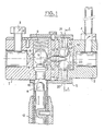
- Figure 1 shows a disengageable coupling according to the invention. It consists of two cylindrical sleeves 1 and 2 in which the shafts of the two parts to be coupled are fixed, by means of screws 3 and 4. A cylindrical casing 5 keeps the two sleeves 1 and 2 assembled.
- a mechanical stop must limit the rotation of the sleeve 2, integral with the reduction gear shaft.
- This stop may be constituted by a steel rod, driven into the screw 4, this rod abutting against two metal bars placed parallel to the axis of rotation of the device, and not being shown in the figure.
- This mechanical stop avoids placing electrical limit switches on the motor, these electrical contacts being much more fragile than the mechanical stop.
- the motor is under-voltaged.
- the sleeve 1 comprises a transverse cylindrical cavity 6 of diameter narrowed at one of its ends, end in which there is a pusher 7 whose shape is adapted to the narrowing.
- a pusher 7 In the cavity 6 can move a ball 8 of very large diameter close to that of the cavity, this ball 8 being wedged between the pusher 7 and a spring 9 fixed to the end of the cavity 6 opposite to the pusher 7.
- the end of the pusher 7 opposite to the ball 8 has a spherical recess 10 suitable for the rounding of a rod 11 placed perpendicular to the longitudinal axis A of rotation of the system.
- This rod (11) slides in a tube (12) integral with the housing. 5.
- the position of the ball 8 when the system is engaged is such that its center of gravity G is placed substantially above the axis (A).
- the ball 8 is in contact with the apex S of one of the conical ends 13 of a cylindrical needle 14, with the same longitudinal axis ⁇ as the assembly.
- the needle 14 is housed in a cylindrical cavity 15 of diameter slightly greater than its own, and the axis ⁇ . At the end of this cavity 15 are produced three cylindrical housings 16, 17 and 18 at 120 0 from each other.
- the rod 11 In the engaged position, the rod 11 is not in contact with the pusher (7) on which the ball 8 under the effect of spring 9.
- the needle 14 touches the ball 8 at a contact point S placed slightly below the center of gravity G.
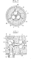
- the other end of the needle 14 spreads the balls 23, 24 and 25 as far as possible , as shown in Figure 2 so that the sleeve 1 rotating under the action of a motor via a reducer drives the sleeve 2 since the balls fit slightly into the holes 20, 21 and 22 .
- Figure 3 shows a longitudinal section of the coupling in the disengaged position.
- the rod 11 has been manually pushed into the hollow 10 of the pusher 7, which by moving then compresses the spring 9.
- the center of gravity G of the ball 8 rises and the needle 14 can then move longitudinally towards the end of the ball in contact with the pusher 7.
- the conical end 26 of the needle 14 moves releasing the 3 balls (23, 24,25) which tend to approach each other and the balls leave the holes (20 , 21 and 22) of the cylindrical cavity 19. If the sleeve 1 rotates under the effect of the engine, the sleeve 2 is no longer driven by the balls and the system is disengaged.
- the coupling according to the invention can automatically disengage if the sleeve 2, in which the valve is fixed, becomes blocked for any reason.
- the three balls 23, 24 and 25 which rotate at the same time as the sleeve 1 collide with the edges of the holes 20, 21 and 22 immobilized so that the radial component of the force acting on the balls makes them bring it closer to the axis thus pushing the needle 14 whose top S of the end 13 slides under the center of gravity G of the ball 8 causing this ball to rise 8.
- the balls 23, 24 and 25 are made of hard steel and the needle 14 is made of very hard hardened steel not wearing out the friction of the balls.
- the end 13 is slightly rounded to prevent the tip from breaking when it bangs against the ball 8 made of hard steel.
- a disengageable coupling has thus been described, the main application of which is the opening or closing of a mixing valve, for individual heating.
Landscapes
- Engineering & Computer Science (AREA)
- General Engineering & Computer Science (AREA)
- Mechanical Engineering (AREA)
- Mechanically-Actuated Valves (AREA)
- Electrically Driven Valve-Operating Means (AREA)
- Multiple-Way Valves (AREA)
Applications Claiming Priority (2)
| Application Number | Priority Date | Filing Date | Title |
|---|---|---|---|
| FR7911990 | 1979-05-11 | ||
| FR7911990A FR2456253A1 (fr) | 1979-05-11 | 1979-05-11 | Accouplement debrayable et son application au fonctionnement d'une vanne |
Publications (1)
| Publication Number | Publication Date |
|---|---|
| EP0019522A1 true EP0019522A1 (fr) | 1980-11-26 |
Family
ID=9225344
Family Applications (1)
| Application Number | Title | Priority Date | Filing Date |
|---|---|---|---|
| EP19800400622 Ceased EP0019522A1 (fr) | 1979-05-11 | 1980-05-08 | Accouplement débrayable et son application au fonctionnement d'une vanne |
Country Status (2)
| Country | Link |
|---|---|
| EP (1) | EP0019522A1 (enExample) |
| FR (1) | FR2456253A1 (enExample) |
Cited By (2)
| Publication number | Priority date | Publication date | Assignee | Title |
|---|---|---|---|---|
| EP0600811A1 (fr) * | 1992-12-04 | 1994-06-08 | CROUZET ElectromÀ©nager | Programmateur à affichage doux |
| WO2022122927A1 (de) * | 2020-12-11 | 2022-06-16 | Nidec Gpm Gmbh | Welle-nabe-verbindung und fluidpumpe aufweisend die welle-nabe-verbindung |
Citations (8)
| Publication number | Priority date | Publication date | Assignee | Title |
|---|---|---|---|---|
| FR1004826A (fr) * | 1947-05-20 | 1952-04-03 | Dispositif à auto-blocage d'un organe mobile | |
| DE1057834B (de) * | 1957-02-11 | 1959-05-21 | Falz U Heftmaschinenwerk Leipz | UEberlastungskupplung |
| GB893932A (en) * | 1959-01-29 | 1962-04-18 | Albert Allen Baker | Torque limit clutch for a wall hydrant |
| FR1366025A (fr) * | 1963-05-02 | 1964-07-10 | Dispositif d'accouplement | |
| US3693381A (en) * | 1971-02-12 | 1972-09-26 | Hill Rockford Co | Torque responsive clutch |
| US3827260A (en) * | 1971-09-25 | 1974-08-06 | T Kato | Shaft-coupling device preventable from over-torque transmission |
| DE2351228A1 (de) * | 1973-10-12 | 1975-04-17 | Daimler Benz Ag | Gangschalteinrichtung fuer zahnraeder- wechselgetriebe, insbesondere fuer kraftfahrzeuge |
| GB1392098A (en) * | 1972-08-18 | 1975-04-23 | Ringspann Maurer Kg A | Spool carrier devices |
-
1979
- 1979-05-11 FR FR7911990A patent/FR2456253A1/fr active Granted
-
1980
- 1980-05-08 EP EP19800400622 patent/EP0019522A1/fr not_active Ceased
Patent Citations (8)
| Publication number | Priority date | Publication date | Assignee | Title |
|---|---|---|---|---|
| FR1004826A (fr) * | 1947-05-20 | 1952-04-03 | Dispositif à auto-blocage d'un organe mobile | |
| DE1057834B (de) * | 1957-02-11 | 1959-05-21 | Falz U Heftmaschinenwerk Leipz | UEberlastungskupplung |
| GB893932A (en) * | 1959-01-29 | 1962-04-18 | Albert Allen Baker | Torque limit clutch for a wall hydrant |
| FR1366025A (fr) * | 1963-05-02 | 1964-07-10 | Dispositif d'accouplement | |
| US3693381A (en) * | 1971-02-12 | 1972-09-26 | Hill Rockford Co | Torque responsive clutch |
| US3827260A (en) * | 1971-09-25 | 1974-08-06 | T Kato | Shaft-coupling device preventable from over-torque transmission |
| GB1392098A (en) * | 1972-08-18 | 1975-04-23 | Ringspann Maurer Kg A | Spool carrier devices |
| DE2351228A1 (de) * | 1973-10-12 | 1975-04-17 | Daimler Benz Ag | Gangschalteinrichtung fuer zahnraeder- wechselgetriebe, insbesondere fuer kraftfahrzeuge |
Cited By (3)
| Publication number | Priority date | Publication date | Assignee | Title |
|---|---|---|---|---|
| EP0600811A1 (fr) * | 1992-12-04 | 1994-06-08 | CROUZET ElectromÀ©nager | Programmateur à affichage doux |
| FR2698926A1 (fr) * | 1992-12-04 | 1994-06-10 | Sextant Avionique | Dispositif d'immobilisation d'une pièce par rapport à un axe traversant cette pièce. |
| WO2022122927A1 (de) * | 2020-12-11 | 2022-06-16 | Nidec Gpm Gmbh | Welle-nabe-verbindung und fluidpumpe aufweisend die welle-nabe-verbindung |
Also Published As
| Publication number | Publication date |
|---|---|
| FR2456253B1 (enExample) | 1983-07-18 |
| FR2456253A1 (fr) | 1980-12-05 |
Similar Documents
| Publication | Publication Date | Title |
|---|---|---|
| EP0220092B1 (fr) | Dispositif de commande d'un moyen d'accouplement tel que par exemple un embrayage ou un variateur de vitesse ou un frein ou analogue | |
| EP2633962B1 (fr) | Structure articulée de robot multi-axes et robot comprenant une telle structure | |
| FR2745059A1 (fr) | Actionneur de vanne | |
| BE1011063A3 (fr) | Accouplement a limitation de couple. | |
| EP1899257A1 (fr) | Dispositif de vissage de bouchons par embrayage magnetique | |
| CA1292030C (fr) | Dispositif de stockage d'energie mecanique a force d'accrochage nulle | |
| EP0019522A1 (fr) | Accouplement débrayable et son application au fonctionnement d'une vanne | |
| CA1164918A (fr) | Dispositif pour couper automatiquement l'alimentation electrique d'un moteur et son utilisation | |
| FR2668204A1 (fr) | Mecanisme de demarreur de moteur. | |
| EP2605256B1 (fr) | Dispositif de commande de la motorisation du dispositif de rearmement du dispositif de fermeture des contacts dans un appareil de protection electrique et appareil le comportant | |
| EP0081024B1 (fr) | Mécanisme d'entraînement sélectif de machines ou dispositifs à partir de l'arbre de prise de force d'un tracteur agricole | |
| FR2508124A1 (fr) | Fourchette de commande pour butee de debrayage et son procede de montage | |
| EP3078101B1 (fr) | Actionneur electrique a moyens manuels d'entrainement | |
| FR2703422A1 (fr) | Dispositif de changement de vitesses pour une boîte de vitesses à engrenages d'un véhicule automobile. | |
| WO2003054404A1 (fr) | Dispositif d'accouplement a crabot | |
| FR2613266A1 (fr) | Outil de prehension et de vissage oriente d'une vis a etrier | |
| FR2728528A1 (fr) | Direction a cremaillere | |
| EP1412651B1 (fr) | Dispositif d'accouplement a crabot | |
| EP2359716A1 (fr) | Dispositif d'assistance à l'ouverture d'un tiroir d'un meuble ou similaire | |
| EP0002092B1 (fr) | Appareil coupe-légumes | |
| EP1880915A1 (fr) | Dispositif de manoeuvre d'aiguillage à commande manuelle | |
| EP0144696A2 (fr) | Dispositif d'entraînement d'une goulotte oscillante | |
| EP0761358B1 (fr) | Outil de taraudage sur presse | |
| EP1680962B1 (fr) | Appareil électrique de traitement de produits alimentaires à sécurité améliorée | |
| FR2530447A1 (fr) | Tournebroche pour four a chaleur tournante |
Legal Events
| Date | Code | Title | Description |
|---|---|---|---|
| PUAI | Public reference made under article 153(3) epc to a published international application that has entered the european phase |
Free format text: ORIGINAL CODE: 0009012 |
|
| AK | Designated contracting states |
Designated state(s): BE CH DE GB IT NL SE |
|
| 17P | Request for examination filed |
Effective date: 19801204 |
|
| STAA | Information on the status of an ep patent application or granted ep patent |
Free format text: STATUS: THE APPLICATION HAS BEEN REFUSED |
|
| 18R | Application refused |
Effective date: 19830218 |
|
| RIN1 | Information on inventor provided before grant (corrected) |
Inventor name: POZZO, CLAUDE |