EP0018971B1 - P-ion controller and control of ionic concentration in a flow-line - Google Patents
P-ion controller and control of ionic concentration in a flow-line Download PDFInfo
- Publication number
- EP0018971B1 EP0018971B1 EP79900433A EP79900433A EP0018971B1 EP 0018971 B1 EP0018971 B1 EP 0018971B1 EP 79900433 A EP79900433 A EP 79900433A EP 79900433 A EP79900433 A EP 79900433A EP 0018971 B1 EP0018971 B1 EP 0018971B1
- Authority
- EP
- European Patent Office
- Prior art keywords
- reagent
- sensors
- set forth
- orifices
- flow stream
- Prior art date
- Legal status (The legal status is an assumption and is not a legal conclusion. Google has not performed a legal analysis and makes no representation as to the accuracy of the status listed.)
- Expired
Links
- 239000003153 chemical reaction reagent Substances 0.000 claims abstract description 76
- 238000000034 method Methods 0.000 claims abstract description 63
- 239000007788 liquid Substances 0.000 claims abstract description 37
- 230000003068 static effect Effects 0.000 claims abstract description 9
- 241000920340 Pion Species 0.000 claims abstract description 7
- 238000011144 upstream manufacturing Methods 0.000 claims abstract description 7
- 238000012935 Averaging Methods 0.000 claims description 13
- 238000006243 chemical reaction Methods 0.000 claims description 8
- 230000004044 response Effects 0.000 claims description 4
- 230000000694 effects Effects 0.000 claims description 2
- 230000008569 process Effects 0.000 abstract description 53
- 239000000203 mixture Substances 0.000 abstract description 11
- 238000012545 processing Methods 0.000 abstract description 4
- 238000000265 homogenisation Methods 0.000 abstract 1
- 238000012544 monitoring process Methods 0.000 abstract 1
- 238000005457 optimization Methods 0.000 abstract 1
- 150000002500 ions Chemical class 0.000 description 5
- 230000008901 benefit Effects 0.000 description 4
- 238000012937 correction Methods 0.000 description 3
- 239000007787 solid Substances 0.000 description 3
- 239000002699 waste material Substances 0.000 description 3
- 230000007812 deficiency Effects 0.000 description 2
- 239000000126 substance Substances 0.000 description 2
- 238000012546 transfer Methods 0.000 description 2
- UFHFLCQGNIYNRP-UHFFFAOYSA-N Hydrogen Chemical compound [H][H] UFHFLCQGNIYNRP-UHFFFAOYSA-N 0.000 description 1
- 239000002253 acid Substances 0.000 description 1
- 239000012445 acidic reagent Substances 0.000 description 1
- 230000002378 acidificating effect Effects 0.000 description 1
- 230000009471 action Effects 0.000 description 1
- 208000012826 adjustment disease Diseases 0.000 description 1
- 238000013459 approach Methods 0.000 description 1
- 230000008859 change Effects 0.000 description 1
- 239000002131 composite material Substances 0.000 description 1
- 238000011109 contamination Methods 0.000 description 1
- 230000007423 decrease Effects 0.000 description 1
- 238000009792 diffusion process Methods 0.000 description 1
- 229910052739 hydrogen Inorganic materials 0.000 description 1
- 239000001257 hydrogen Substances 0.000 description 1
- 238000007654 immersion Methods 0.000 description 1
- 238000002347 injection Methods 0.000 description 1
- 239000007924 injection Substances 0.000 description 1
- 238000009434 installation Methods 0.000 description 1
- 230000014759 maintenance of location Effects 0.000 description 1
- 230000007935 neutral effect Effects 0.000 description 1
- 230000003472 neutralizing effect Effects 0.000 description 1
- 229920000642 polymer Polymers 0.000 description 1
- 230000000717 retained effect Effects 0.000 description 1
- 239000002002 slurry Substances 0.000 description 1
- 230000001131 transforming effect Effects 0.000 description 1
- 239000002351 wastewater Substances 0.000 description 1
- XLYOFNOQVPJJNP-UHFFFAOYSA-N water Substances O XLYOFNOQVPJJNP-UHFFFAOYSA-N 0.000 description 1
Images
Classifications
-
- G—PHYSICS
- G05—CONTROLLING; REGULATING
- G05D—SYSTEMS FOR CONTROLLING OR REGULATING NON-ELECTRIC VARIABLES
- G05D21/00—Control of chemical or physico-chemical variables, e.g. pH value
- G05D21/02—Control of chemical or physico-chemical variables, e.g. pH value characterised by the use of electric means
Definitions
- tanks are more expensive than (plug-flow) pipeline, and turbine mixers not only more expensive but also more vulnerable than passive mixers.
- the present invention intends to reduce the "complex system of instruments" to a compact, effective system giving accurate pH or pion control in the process line with its inherent plug flow, at least as satisfactory as previously possible with mixing tanks and active mixers.
- a method of controlling ionic characteristics in a flow line having a stream flowing therein comprising the steps of distributing a pattern of pH or pion sensors having an inherent logarithmic analog output over the cross-sectional area of the flow line to generate individual sensor signals in response to the characteristics detected by each of the sensors, converting each of the signals to its antilogarithms, digitizing the signals before or after conversion to antilogarithms, averaging all the antilogarithms, converting the average antilogarithm to a binary control word, providing reagent orifices downstream of the sensors in a pattern distributed across the cross section of the flow stream, controlling the release of the reagent to the orifices from individual reagent dispensers in accordance with the binary control word, and mixing the flow stream downstream of the reagent orifices to homogenize it.
- an apparatus for controlling the ionic characteristics of a stream of liquid flowing in a line comprising an array of pH of P-ion sensors having an inherent logarithmic analog output distributed across the cross section of the line, each of the sensors being connected to an individual antilogging means, the array of antilogging means being connected to an averaging means, with a digitizing means being connected either between the sensors and the antilogging means or between the antilogging means and the averaging means, the averaging means being connected to a binary signal generating means for providing a binary control word, a system for dispensing reagent including an array of orifices distributed over the cross section of the flow stream downstream of the sensors, an array of reagent dispensers connected to the reagent orifice array, control means connecting each of the dispensers to the binary control word generating means for controlling the release of the reagent from each of the dispensers in accordance with the characteristics detected by the sensors, and mixing means in the line downstream of the reagent orifices to homogen
- the present invention consists of a number of steps, some of which are separately applicable in other situations, which speed up the necessary mass transfer operations to the degree required for successful total control of the reaction directly performed in the process line itself.
- This line may be a pipe, or a ditch as is common in wastewater processing.
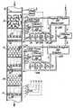
- an orifice flowmeter is designated by 1.
- any accurate flowmeter with electrical signal output may be used.
- the process line is an open ditch, a metering flume will be more appropriate.
- 2 designates a static mixer of the backmixing type, symbolized by a bed of "Raschig Rings". These rings are sections of thin-walled tubing, about as high as they are wide. Such a bed not only repeatedly splits and joins separate stream threads of the process liquid, but within the cavities of the rings some process liquid is retained and released at a slower rate than the average process flow rate, producing the effect of backmixing. The end result is that a step- change of composition in the process stream is stretched into a ramp-change of composition, radially homogeneous from pipe-wall to pipeline center, rather than with a parabolic front as in plug flow.
- a grid across the process line carrying a number of composition sensors is designated by 3. These sensors have to operate reliably under total immersion under some ambient over-pressure.
- the sensors should be positioned such that shear flow across their sensitive faceplate maximizes fast response.
- the grid supporting the sensors may be followed by or be made part of, the distribution system which dispenses reagent evenly over the cross-section of the process stream, as shown by 4. It is advantageous to create local turbulence in the process liquid at the dispensing orifices in order to speed up the adjustment reaction between reagent and process liquid. Further mixing is enhanced by the non-backmixing static mixer 5.
- Such a static mixer is symbolized by a bed of spheres which split up and recombine the process stream without retention or backmixing, hence without introduction of deadtime between the reagent dispenser and the next grid of sensors.
- Various types of effective non-backmixing static mixers are commercially available.
- the static mixer 5 should be followed by the final sensor assembly 6 unless the control section is duplicated as discussed below.
- the sensors in grid 6 may be positioned as shown in grid 3, or in any different way which enhances shear flow of process liquid across their sensitive faceplates, as is shown in 6 by the use of flow deflectors.
- the final sensor-supporting grid also carries a reference electrode 7, again preferably of the type described in U.S. Patent No. 4,133,732, issued January 9, 1979 consisting of an electrode embedded in gelled endpoint-composition process liquid. By locating this reference electrode at the end of the composition-adjustment sections, there is minimum possibility of contamination of the reference gel in the long run. This reference electrode designates the base potential from which the signal potential of each of the many sensor electrodes is measured.
- mixer 5 and sensor grid 6 another reagent dispensing section containing elements 8, 9, and 10 which are identical to respective elements 3, 4 and 5 may be inserted to fine- tune process liquid composition adjustment.
- a third and fourth section dispensing a different type of reagent may be added also.
- the electrical composition-related signals put out by the sensors are processed electronically in a way to be discussed further down, to one signal going to the reagent dispensing control valves 11, 12, 13, ... 18, 19.
- This command signal is digital, and has the form of a binary number or "word". Such a number consists of the digits 1 and 0, wherein a 1 causes the solenoid of a specific on-off solenoid valve to be energized and the valve opened. The appearance of a 0 for that particular valve, de-energizes the solenoid and causes the valve to close.
- every digit in the word may command its own valve.
- valves are placed parallel to each other between a reagent reservoir under constant overpressure and the process line, and if each adjacent valve counting from the valve controlled by the least significant bit, is provided with an orifice which allows twice as much reagent to flow through as its smaller neighbor, every more significant bit in the control word commands a reagent flow twice as large as the flow commanded by its adjacent less significant bit.
- the total flow of the control valve assembly now becomes directly related to the total numerical value of the control command word. For example: a word of 10 binary digits or bits commands a total flow of from 0 to 1024 arbitrary units of flow although the diameters of the orifices in the 10 control valves only increase from 1 to 32 arbitrary length units.
- the subdivision in 10, or any other desired number of valves makes possible a very fast and very reproducible reagent flow control responding to commands for minute increases or decreases as fast as for large changes.
- Differential pressure controller 20 causes a constant pressure differential in the reagent liquid from reservoir 21 across the control valves to process line pressure at 22, e.g. by pressurizing the reagent reservoir with air.
- a flow of carrier liquid 23 insures rapid transportation of even small amounts of reagent to the dispensing orifices in the process line at 4.
- This carrier liquid may be water or process liquid from the process stream, moved by a separate pump.
- the drawing shows addition of controlled amount of liquid reagent.
- slurry or powdered solid reagents can be added to the carrier liquid by feeders with sequentially doubling capacities, controlled by a binary control word.
- the second, downstream, section may be fed from a similar control valve assembly 24, which now advantageously dispenses diluted reagent 25 from dilutor 26 in order to make possible a wider range of controlled reagent addition to the process stream.
- the reservoir of diluted reagent should be pressurized to a constant pressure differential over control valves 24, by differential pressure controller 27, just as was done with the previous control section.
- the second control section may advantageously narrow the final control range of the adjusted process liquid composition by using liquid reagent.
- the second, or any identical additional, control section may control the addition of a different reagent to correct a different deficiency in the process liquid, as e.g. acidic versus alkaline reagent in correcting the pH of the process stream which may be above as well as (at some other time) below the desired pH.
- the electrical signal derived from the sensors in that section will decide whether the section's reagent addition will be activated, or whether the pH calls for addition of different reagent from another section.
- the system of on-off control valves can shut off tight; something which should not be counted on with present-day control valves. Since leakage means extra chemicals to be neutralized, it represents waste.
- the electrical signal of the sensor electrodes has to be processed.
- Sensor electrodes by their nature have an output which is the logarithm of actual ionic concentration in the liquid to be measured. Should different electrode outputs, representing locally different ionic concentrations, be averaged directly by connecting in parallel, an average of the logarithms of ionic concentration differences would be obtained which mathematically may be called a geometric average. However, the actual difference in ion concentrations should be averaged by algebraic addition of these concentrations (and then division by the number of sensors), an operation of which the logarithm cannot be taken. Hence not geometrical, but arithmetical averaging is required. This refinement becomes meaningful if unbuffered process liquids have to be neutralized.
- the sensors should be positioned in such a way over the cross-section of the process line, that each represents a stream of process liquid of about equal volume.
- the averaged digital antilog output of the sensors lends itself directly to subtraction of the number of ion equivalents of reagent introduced into the process stream to produce the desired endpoint concentration; this output can also be multiplied by a variable factor, like process flow rate from flowmeter 1 or buffer capacity of the process liquid, computed from the downstream sensor response to a certain addition of reagent.
- All these computational manipulations of the averaged sensor signal, and its process into a valve command word of the proper format may be done inexpensively by microprocessor 29 for the first, and 30, for the second control section in the drawing.
- Modern electronic technology may allow combination of all operations done by separately presented circuit units 28, 29 and 30, in one VLSI (very large scale integrated circuit). This electronic processing is done momentary; in combination with the fast acting control valves, an inexpensive and sophisticated control action can be effected sufficiently fast to produce locally, on-line, the same satisfactory control as is obtained today with voluminous mixing tanks and active mixers, in batchwise control.
Landscapes
- Physics & Mathematics (AREA)
- General Physics & Mathematics (AREA)
- Engineering & Computer Science (AREA)
- Automation & Control Theory (AREA)
- Control Of Non-Electrical Variables (AREA)
- Accessories For Mixers (AREA)
- Automatic Analysis And Handling Materials Therefor (AREA)
Applications Claiming Priority (2)
| Application Number | Priority Date | Filing Date | Title |
|---|---|---|---|
| US900908 | 1978-04-28 | ||
| US05/900,908 US4181951A (en) | 1978-04-28 | 1978-04-28 | In-line pH and pIon controller |
Publications (3)
| Publication Number | Publication Date |
|---|---|
| EP0018971A4 EP0018971A4 (en) | 1980-06-23 |
| EP0018971A1 EP0018971A1 (en) | 1980-11-26 |
| EP0018971B1 true EP0018971B1 (en) | 1983-04-27 |
Family
ID=25413284
Family Applications (1)
| Application Number | Title | Priority Date | Filing Date |
|---|---|---|---|
| EP79900433A Expired EP0018971B1 (en) | 1978-04-28 | 1979-12-04 | P-ion controller and control of ionic concentration in a flow-line |
Country Status (6)
| Country | Link |
|---|---|
| US (1) | US4181951A (enExample) |
| EP (1) | EP0018971B1 (enExample) |
| JP (1) | JPS633323B2 (enExample) |
| CA (1) | CA1116719A (enExample) |
| DE (1) | DE2965265D1 (enExample) |
| WO (1) | WO1979000998A1 (enExample) |
Families Citing this family (8)
| Publication number | Priority date | Publication date | Assignee | Title |
|---|---|---|---|---|
| US4762796A (en) * | 1981-10-05 | 1988-08-09 | Exxon Research And Engineering Company | pH control of a process stream |
| US4648043A (en) * | 1984-05-07 | 1987-03-03 | Betz Laboratories, Inc. | Computerized system for feeding chemicals into water treatment system |
| US4766550A (en) * | 1985-10-30 | 1988-08-23 | Westinghouse Electric Corp. | Automatic on-line chemistry monitoring system |
| GB8614530D0 (en) * | 1986-06-14 | 1986-07-23 | Clean Water Co Ltd | Liquid treatment process |
| US5073499A (en) * | 1988-04-15 | 1991-12-17 | Westinghouse Electric Corp. | Chemical diagnostic system |
| US5481260A (en) * | 1994-03-28 | 1996-01-02 | Nordson Corporation | Monitor for fluid dispensing system |
| US5696696A (en) * | 1994-10-11 | 1997-12-09 | Betzdearborn, Inc. | Apparatus and method for automatically achieving and maintaining congruent control in an industrial boiler |
| US5923571A (en) * | 1994-10-11 | 1999-07-13 | Betzdearborn, Inc. | Apparatus and method for automatic congruent control of multiple boilers sharing a common feedwater line and chemical feed point |
Family Cites Families (7)
| Publication number | Priority date | Publication date | Assignee | Title |
|---|---|---|---|---|
| US3072146A (en) * | 1959-09-24 | 1963-01-08 | Gizeski Terrence | Digital regulator valve |
| US3664951A (en) * | 1970-07-22 | 1972-05-23 | Pollution Engineering Internat | Apparatus and process to treat waste water for pollution control and industrial reuse |
| US3718556A (en) * | 1970-07-22 | 1973-02-27 | Magna Corp | Ionic ph control |
| US3791793A (en) * | 1972-01-31 | 1974-02-12 | Leeds & Northrup Co | Adaptive feed forward-feedback control of the concentration of a selected ion of a solution |
| IT995258B (it) * | 1972-10-12 | 1975-11-10 | Benckiser Gmbh Joh A | Dispositivo per la misurazione del potenziale di ossiriduzione di mezzi liquidi |
| US3856668A (en) * | 1973-05-30 | 1974-12-24 | R Shubert | Method for treatment of coal washery waters |
| JPS5920974B2 (ja) * | 1976-12-28 | 1984-05-16 | 電気化学工業株式会社 | 流液のph自動制御装置 |
-
1978
- 1978-04-28 US US05/900,908 patent/US4181951A/en not_active Expired - Lifetime
-
1979
- 1979-04-16 DE DE7979900433T patent/DE2965265D1/de not_active Expired
- 1979-04-16 JP JP54500716A patent/JPS633323B2/ja not_active Expired
- 1979-04-16 WO PCT/US1979/000236 patent/WO1979000998A1/en not_active Ceased
- 1979-04-27 CA CA000326485A patent/CA1116719A/en not_active Expired
- 1979-12-04 EP EP79900433A patent/EP0018971B1/en not_active Expired
Also Published As
| Publication number | Publication date |
|---|---|
| DE2965265D1 (en) | 1983-06-01 |
| WO1979000998A1 (en) | 1979-11-29 |
| EP0018971A4 (en) | 1980-06-23 |
| JPS55500241A (enExample) | 1980-04-24 |
| CA1116719A (en) | 1982-01-19 |
| US4181951A (en) | 1980-01-01 |
| JPS633323B2 (enExample) | 1988-01-22 |
| EP0018971A1 (en) | 1980-11-26 |
Similar Documents
| Publication | Publication Date | Title |
|---|---|---|
| EP0018971B1 (en) | P-ion controller and control of ionic concentration in a flow-line | |
| KR100331213B1 (ko) | 액체 혼합물 제조 방법 및 장치 | |
| US5246026A (en) | Fluid measuring, dilution and delivery system | |
| US6129104A (en) | Method for automotive dose control of liquid treatment chemicals | |
| US4642222A (en) | Polymer feed system | |
| US3791793A (en) | Adaptive feed forward-feedback control of the concentration of a selected ion of a solution | |
| US20050058548A1 (en) | Method of controlling fluid flow | |
| US4938256A (en) | Apparatus for the production of particular concentrations of gaseous materials as well as for mixing various gaseous materials in a specified ratio | |
| Brown et al. | Modeling and interpreting oxygen transfer data | |
| Benefield et al. | A kinetic model for the activated sludge process which considers diffusion and reaction in the microbial floc | |
| Midoux et al. | Limits of the chemical method for the determination of physical mass transfer parameters in mechanically agitated gas‐liquid reactors | |
| JPH0221875B2 (enExample) | ||
| Schulz et al. | The role of mixing in ozone dissolution systems | |
| JPS57149950A (en) | Method for determination of hydrogen peroxide | |
| CN217786978U (zh) | 一种变比例稀释法测量电导率的装置 | |
| CN219252432U (zh) | 注液设备 | |
| CN217437844U (zh) | 一种基于氨浓度分析仪的加药系统 | |
| CN217288206U (zh) | 一种pH调控装置 | |
| US4875178A (en) | Method to control the discharge of effluent | |
| KR20030035855A (ko) | 액체 처리 화학물질을 자가 보정 방식으로 용량 제어하는방법 | |
| CN222961233U (zh) | 一种用于智慧臭氧系统的在线精确投加小试装置 | |
| CN217650963U (zh) | 污水处理系统用精确加药的pH值调节装置 | |
| CN118883199B (zh) | 一种用于电感耦合等离子体质谱的碱性液体自动化处理装置及方法 | |
| CN217139983U (zh) | 一种在线自动调节液体pH的装置 | |
| Agunwamba | Boundary conditions for the waste stabilization pond |
Legal Events
| Date | Code | Title | Description |
|---|---|---|---|
| PUAI | Public reference made under article 153(3) epc to a published international application that has entered the european phase |
Free format text: ORIGINAL CODE: 0009012 |
|
| 17P | Request for examination filed | ||
| AK | Designated contracting states |
Designated state(s): CH DE FR GB SE |
|
| GRAA | (expected) grant |
Free format text: ORIGINAL CODE: 0009210 |
|
| AK | Designated contracting states |
Designated state(s): CH DE FR GB SE |
|
| REF | Corresponds to: |
Ref document number: 2965265 Country of ref document: DE Date of ref document: 19830601 |
|
| ET | Fr: translation filed | ||
| PGFP | Annual fee paid to national office [announced via postgrant information from national office to epo] |
Ref country code: FR Payment date: 19840514 Year of fee payment: 6 |
|
| PGFP | Annual fee paid to national office [announced via postgrant information from national office to epo] |
Ref country code: CH Payment date: 19840516 Year of fee payment: 6 |
|
| PGFP | Annual fee paid to national office [announced via postgrant information from national office to epo] |
Ref country code: DE Payment date: 19840612 Year of fee payment: 6 |
|
| PGFP | Annual fee paid to national office [announced via postgrant information from national office to epo] |
Ref country code: SE Payment date: 19840630 Year of fee payment: 6 |
|
| PG25 | Lapsed in a contracting state [announced via postgrant information from national office to epo] |
Ref country code: GB Effective date: 19880416 |
|
| PG25 | Lapsed in a contracting state [announced via postgrant information from national office to epo] |
Ref country code: SE Effective date: 19880417 |
|
| PG25 | Lapsed in a contracting state [announced via postgrant information from national office to epo] |
Ref country code: CH Effective date: 19880430 |
|
| GBPC | Gb: european patent ceased through non-payment of renewal fee | ||
| PG25 | Lapsed in a contracting state [announced via postgrant information from national office to epo] |
Ref country code: FR Free format text: LAPSE BECAUSE OF NON-PAYMENT OF DUE FEES Effective date: 19881229 |
|
| REG | Reference to a national code |
Ref country code: CH Ref legal event code: PL |
|
| PG25 | Lapsed in a contracting state [announced via postgrant information from national office to epo] |
Ref country code: DE Effective date: 19890103 |
|
| REG | Reference to a national code |
Ref country code: FR Ref legal event code: ST |
|
| EUG | Se: european patent has lapsed |
Ref document number: 79900433.8 Effective date: 19890725 |
|
| PLBE | No opposition filed within time limit |
Free format text: ORIGINAL CODE: 0009261 |
|
| STAA | Information on the status of an ep patent application or granted ep patent |
Free format text: STATUS: NO OPPOSITION FILED WITHIN TIME LIMIT |