EP0018865B1 - Konzentrator-Dekonzentrator-Vorrichtung - Google Patents
Konzentrator-Dekonzentrator-Vorrichtung Download PDFInfo
- Publication number
- EP0018865B1 EP0018865B1 EP19800400449 EP80400449A EP0018865B1 EP 0018865 B1 EP0018865 B1 EP 0018865B1 EP 19800400449 EP19800400449 EP 19800400449 EP 80400449 A EP80400449 A EP 80400449A EP 0018865 B1 EP0018865 B1 EP 0018865B1
- Authority
- EP
- European Patent Office
- Prior art keywords
- concentrator
- junctions
- time switch
- matrix
- deconcentrator
- Prior art date
- Legal status (The legal status is an assumption and is not a legal conclusion. Google has not performed a legal analysis and makes no representation as to the accuracy of the status listed.)
- Expired
Links
Images

Classifications
-
- H—ELECTRICITY
- H04—ELECTRIC COMMUNICATION TECHNIQUE
- H04Q—SELECTING
- H04Q11/00—Selecting arrangements for multiplex systems
- H04Q11/04—Selecting arrangements for multiplex systems for time-division multiplexing
Definitions
- the present invention relates to a concentrator-deconcentrator device based on symmetric temporal matrices (MTS) for time telephone exchanges using the Pulse Modulation and Coding (MIC) technique.
- MTS symmetric temporal matrices
- MIC Pulse Modulation and Coding
- the concentration devices make it possible to connect a greater number of subscribers to a telephone exchange or automatic branch exchange than the total number of entries in the connection network contained in the exchange. This is based on the observation that all the subscribers do not use their line at the same time, which makes it possible to give access simultaneously to the connection network only to a part of them, and therefore to reduce the size. of this network.
- the MIC technique consists in sampling the voice signals at a rate of 8 kHz then in quantifying and coding these samples in the form of digital signals in which each sample is represented by a word of eight binary elements.
- Time division multiplexing enables signals from separate subscribers to be transmitted via a single digital MIC junction, such multiplexing conventionally making it possible to obtain 24 or 30 telephone channels per junction (CCITT standards).
- a known symmetric time matrix is described in the document FR-A-2 341 999, it makes it possible to switch the samples transmitted by eight incoming time junctions bound for eight outgoing time junctions so that a sample transmitted by the one of the incoming trunks can be switched to any of the outgoing trunks.
- Internal addressing circuits make it possible to modify the organization of the 256 space-time paths possible under the control of an external signal.
- Document FR-A-2 370 393 discloses a concentrator-deconcentrator device comprising, as space-time switching elements of the MTS, device with a fixed concentration (or deconcentration) ratio.
- This device is not symmetrical, does not provide inputs for injecting tones and test signals, and it is not modular: if you want to increase traffic, you need to use three stages of matrices ( Figure 5) , which complicates the realization of the device.
- Figure 5 three stages of matrices
- the present invention relates to a two-stage digital concentrator-deconcentrator device, comprising, as space-time switching elements of the MTS, which is symmetrical, decentralized and modular, does not have the drawbacks of known devices, and has an easily modifiable concentration ratio.
- the concentrator-deconcentrator device comprises a centralized part composed of central modules common to the concentrator and to the deconcentrator and decentralized parts belonging respectively one to the concentrator of the device and the other to the deconcentrator, these decentralized parts being associated with the terminal modules containing the subscriber and circuit equipment, the common central modules each comprise symmetrical time matrices inserted between the PABX junctions and the subscriber MIC junctions, and the terminal modules each comprise symmetric time matrices inserted between subscriber MIC junctions and subscriber and circuit equipment.
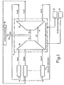
- the concentration device 1 presented in FIG. 1 consists of a concentrator 2 and a deconcentrator 3 and it is connected to an automatic exchange 10.
- the concentrator 2 is connected by its output to the input of the deconcentrator 3 by means of q connections. local C1.
- the inputs of the concentrator 2 are constituted by n MIC junctions of subscribers Ae, originating from p terminal modules referenced 4 to 9, n being preferably multiple of p.
- the p terminal modules constitute a terminal unit.
- the outputs of the concentrator 2 are connected by m junctions of the PABX Se to the PABX 10, m being less than n.
- the inputs of the deconcentrator 3 are connected to the automatic switch 10 by m junctions MIC of automatic switch referenced Es and the outputs of the deconcentrator 3 are connected to the terminal modules by n junctions MIC of subscribers As.
- nG48, p ⁇ 6 and 2, ⁇ m, ⁇ 24 each terminal module being connected to 8 junctions of subscribers Ae and to 8 junctions of subscribers As, 2, ⁇ q ⁇ , 24 local links connecting the concentrator 2 to the deconcentrator 3.
- Two microprocessors 13 and 14 conventionally provide control of the device 1 and more particularly of symmetric time matrices.
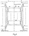
- FIG. 2 is a schematic description of the structure of the concentrator-deconcentrator device 1. To simplify the drawing, the junctions Se and Es and the local connections C1 have not been represented inside the concentrator-deconcentrator device 1.
- the concentrator 2 consists of a decentralized first stage 101 formed by p terminal modules 4 to 9 and a centralized second stage 102 formed by the concentration part of "r" central modules referenced 103 to 108, the number r of these central modules varying preferably from a minimum of 2 for security reasons to a maximum of 6 depending on the traffic to be carried.
- the deconcentrator 3 consists of a first centralized stage 109, formed from the deconcentration part of the r central modules referenced 103 to 108, and a second, decentralized stage 110, formed from the p terminal modules 4 to 9.
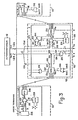
- FIG. 3 represents a basic modular part of the concentrator-deconcentrator device 1, that is to say, on the one hand, part of the first stage 101 of the concentrator 2 and part of the second stage 110 of the deconcentrator 3, located for example in the terminal module 4, as well as, on the other hand, part of the second stage 102 of the concentrator 2 and part of the first stage 109 of the deconcentrator 3, located, for example, in the central module 103.
- the first decentralized stage 101 of the concentrator 2 comprises, in each terminal module such as the terminal module 4, a group of multiplexers 200 consisting for example of 8 multiplexers; to simplify the drawing of Figure 3, only one of these multiplexers has been shown.
- Each multiplexer of the multiplexer group 200 receives on an input 201 a MIC junction coming from a set of terminal cards 202 comprising all the terminal cards contained in the terminal module 4, knowing that the subscriber and circuit equipment of a module are distributed on these terminal cards and that the total number of devices in a module is preferably limited to 256.
- a second input 203 of each multiplexer of the group of multiplexers 200 receives a MIC junction connected to a connection point of a set connection points 204.
- connection point of all the connection points 204 is connected to 1 return junction to all of the terminal cards 202.
- the decentralized stage 101 further comprises, in each terminal module such as the terminal module 4, a first symmetric time matrix 205 having two inputs, one connected to a "0", the other to a "1" logic.
- the output junctions of the matrix 205 address the multiplexers of group 200.
- the output junctions of this group of multiplexers 200 constitute the inputs of a second symmetrical time matrix 206, of which a part of the outputs constitutes the outputs of the first stage 101 of the concentrator 2.
- the other outputs of the matrix 206 are not used.
- the symmetric temporal matrices are of the 8 by 8 type and the matrices 206 have two unused outputs.
- the second centralized stage 102 of the concentrator 2 comprises a symmetric time matrix in each central module such as the matrix 207 in the central module 103.
- Six inputs of the matrix 207 are connected to the first stage 101 so that the output no. i (1 ⁇ i ⁇ 6) from terminal module no. j (1 ⁇ j ⁇ 6), constituted by an output of an MTS such that the matrix 206 is connected to the input no. j of the central module no. i, constituted by an entry of a symmetric temporal matrix such as the matrix 207.
- Another input Em of the matrix 207 receives the signaling sent, for security reasons, by two inputs of the multiplexer 216. This signaling is sent to the automatic exchange 10.
- a last Toc input of the matrix 207 receives tone 1 or tone 2 tones transmitted by a multiplexer 208 and to be transmitted equal to the PABX 10.
- the outputs of the matrix 207 are connected, on the one hand, to 1 to 4 MIC junctions Se directed towards the automatic switch 10 and, on the other hand, to 1 to 4 MIC junctions C1 c used to establish local connections C1. These two groups of junctions are also connected to the inputs of a multiplexer 211.
- the output Tr of the multiplexer 211 is connected to a test device which makes it possible to check the continuity of a path established through the concentrator-deconcentrator device 1.
- the first centralized stage 109 of the deconcentrator 3 comprises, in each central module such as the central module 103, two groups of multiplexers 212 and 213, each consisting of 1 to 4 multiplexers, as well as two symmetrical time matrices 214 and 215. To simplify the diagram of FIG. 3, only one multiplexer of each of the 2 groups of multiplexers 212 and 213 has been represented. Inside each of the two groups of multiplexers 212 and 213, each multiplexer receives as input a junction of Te test.
- Each multiplexer of the group of multiplexers 212 also receives an input junction Es from the automatic switch 10 and each multiplexer of the group of multiplexers 213 receives as input a junction C 1 d itself connected to one of the junctions Cl c, previously described , via a local connection C1 junction.
- the matrix 214 has 2 connected inputs, one with a logical "0", the other with a logical "1".
- 1 to 4 junctions address the 1 to 4 multiplexers of group 212 and the 1 to 4 other junctions address the 1 to 4 multiplexers of group 213.
- the 1 to 4 output junctions in 1 to 4 multiplexers of group 212 and the 1 to 4 output junctions of 1 to 4 multiplexers of group 213 are connected to inputs of matrix 215.
- An output Re of matrix 215 restores the signaling emitted by the automatic exchange 10 on one of the junctions Es and through a multiplexer of the group of multiplexers 212.
- the second decentralized stage 110 of the deconcentrator 3 comprises in each terminal module such as the terminal module 4 a symmetric time matrix 217 including certain inputs provided in number 6 in the solution presented, are connected to the first stage 109 respecting the principle of connection of the first and second stages 109 and 110 described above: the output no. K (1 ⁇ , k, ⁇ 6) of the central module no.
- the concentrator-deconcentrator device 1 provides the concentration of 48 MIC junctions of Ae subscribers 32-way, on 2 to 24 MIC switches PBX Se 32-way and vice versa, switching from 2 to 24 MIC junctions Es switch on 48 MIC subscribers As.
- the concentrator-deconcentrator device 1 also performs ancillary functions such as the establishment of local communications between two subscribers, a subscriber and a circuit, or two circuits belonging to the same subscriber terminal unit, the transmission of tones, the transmission of signaling to and from the PABX 10 as well as the continuity test of a path established through the concentrator-deconcentrator device 1.
- the concentration function relates to the first and second stages 101 and 102 of the concentrator 2.
- the symmetric time matrix 205 receives from one of the microprocessors 13 and 14, instructions ordering or no the continuity test of a space-time path established in the concentrator-deconcentrator device 1.
- the logic value "1" is not transmitted on any of the channels of the 8 junctions of output of the matrix 205.
- the multiplexers of the group of multiplexers 200 addressed by logic "0" present on their outputs the states of the 8 junctions coming from the set 202 of the terminal cards of the terminal module 4.
- the symmetric time matrix 206 concentrates digital signals received from these 8 junctions on 1 to 6 outgoing junctions depending on the amount of traffic.
- the digital samples transmitted during the IT time intervals available on the input junctions of the matrix 206 are allocated time intervals available on the 1 to 6 output junctions according to the instructions received by this matrix 206.
- the output junctions of the matrix 206 are each connected to a central module according to the principle of connection of the stages 101 and 102 stated above.
- the matrix 207 concentrates the samples received via the 6 junctions Ae originating from the 6 terminal modules, such as the terminal module 4, on 1 to 4 junctions Se.
- the concentration ratio of each central module therefore varies from 3/2 to 6 in the case of maximum equipment of the subscriber terminal unit.
- the deconcentration function relates to the first and second stages 109 and 110 of the deconcentrator 3.
- the matrix 214 receives from one of the microprocessors 13 and 14, instructions ordering or not the test of continuity of a path spatio-temporal established in the concentrator-deconcentrator device 1.
- the logic value "1" is not transmitted on any of the channels of the 8 output junctions of the MTS 214.
- the multiplexers of the group of multiplexers 212 addressed by logic "0" s, present at output the states of the input junctions Es.
- the matrix 215 transfers the states of the output junctions of each of the multiplexers of group 212 to the outgoing junctions As. These junctions As are connected to the parts of the second stage 110 situated in the terminal modules according to the principle of connection of stages 109 and 110 stated previously.
- the matrix 217 routes the input junctions Ae coming from the central modules towards the output junctions, each of them being connected to a connection point of all the connection points 204 located in the stage 101, so that these junctions are connected to the corresponding junctions, in the direction of the assembly 202 of the terminal cards.
- a voice signal sample coming from the subscriber B in communication with the subscriber A, is found on a junction y line Es, at the entrance of the deconcentrator 3 and, more precisely at the input of the same central module as that used by the concentrator 2 for routing the voice signal sample from subscriber A to the automatic exchange 10, in this case in the example chosen, the central module 103
- This channel y is connected to a channel x via a multiplexer from the group of multiplexers 212 and MTS 215 and 217, this channel x is itself connected to the corresponding channel x back to all of the terminal cards such as the assembly 202 located in the terminal module 4.
- Local communications can be established directly, without passing through the automatic exchange 10, between 2 subscribers A and C whose equipment is located in the same subscriber terminal unit.
- the voice signal sample coming from a subscriber A whose station is connected to a terminal card of the assembly 202 is transmitted through a multiplexer of the group of multiplexers 200 and the matrix 206.
- This sample transmitted by the junction Ae of rank i leaving the matrix 206 is directed towards the central module of rank i.
- the sample is presented at the first input junction of the matrix 207 in the central module 103.
- the instructions received by the matrix 207 control the output of the sample on one of the four junctions C1c.
- the chosen C1c junction is connected to a corresponding C1d junction by a local connection C1 so that the voice signal sample is retransmitted through a multiplexer of the group of multiplexers 213 on input of the matrix 215.
- the instructions received by this matrix 215 determine, depending on the terminal module in which the terminal card corresponding to the subscriber C is located, the junction As of rank k of the matrix 215 on which the sample will be transmitted.
- the central module concerned is the module 103 in the example chosen, the sample passes from this junction As of rank k to the first input junction of the matrix 217, in the terminal module of rank k, ie the terminal module 4.
- the voice signal sample then reaches subscriber C, whose extension is connected to the set of terminal cards.
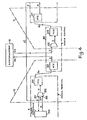
- FIG. 5 presents in a simplified manner an example of round-trip paths established between the subscribers A and C in local communication, the connection of A to C having been detailed previously from FIG. 3.
- a voice signal sample presented on channel x at the input of the matrix 206 of the terminal module 4 is transmitted on a channel r of the first output junction of the matrix 206 and, consequently, on a channel r of the first input junction of the matrix 207 of the central module 103.
- this channel r is connected to a channel s of a local junction C1 and therefore of an input junction of the matrix 215.
- the terminal module of rank k in which the terminal card corresponding to the subscriber C is located is, among the terminal modules 4 to 9 presented in FIG.
- the voice signal sample of subscriber A is found on a channel t of the five uth output junction of the matrix 215.
- this sample is also found on channel t of the first input junction of a symmetric time matrix 219 of the terminal module 8, equivalent to the matrix 217 of the terminal module 4.
- the matrix 219 By through the matrix 219 the sample occurs on a path z of a output junction of this matrix 219, junction which is connected to a return junction to all of the terminal cards 220 comprising the subscriber equipment C.
- the subscriber voice signal sample C is presented on channel z at the input of a symmetric time matrix 221 of the terminal module 8.
- the instructions received by the matrix 221 control the output of the sample on a channel t 'of an output junction of rank i of the matrix 221.
- the sample then occurs on a channel t' of the twenty-first output junction of the matrix 221 then on a channel t 'of the fifth input junction of a symmetric time matrix 222 of the central module 104.
- this channel t' is connected to a channel s 'd' a local junction C1 ′ therefore of an input junction of a symmetric time matrix 223.
- the voice signal sample of subscriber C is found on a channel r ′ of the first output junction of the matrix 223 and , consequently, on a channel r 'of the second input junction of the matrix 217 of the terminal module 4.
- the sample is presented on the channel x of an output junction of the matrix 217, junction which is connected to a return junction to the set of terminal cards 202 comprising the subscriber equipment A.
- the concentrator-deconcentrator device 1 also transmits tones, on the one hand to all of the terminal cards such as the assembly 202 located in the terminal module 4, on the other hand to the automatic branch exchange 10. In the first case the tones must be emitted without blocking. This is why the emission of these tones is carried out from the second stage 110 of the deconcentrator 3.
- one of the tones tone 3 and tone 4 presented at the input of the multiplexer 218 is transmitted by the multiplexer 218 on the input junction Tod then on the junction As of rank p of the matrix 217.
- This p th junction As being connected to a connection point of all the connection points 204 located in the first stage 101 of the concentrator 2, the tone 3 or tone 4 is emitted towards the p th subscriber junction returning to the set of terminal cards 202.
- the tone tones 3 and tone 4 are directly emitted on the two remaining available inputs of the matrix 217.
- the multiplexer 218 is therefore eliminated.
- the transmission of the tones to the automatic switch 10 takes place from the second stage 102 of the concentrator 2.
- one of the tone 1 and tone 2 tones presented at the input of the multiplexer 208 is transmitted by this multiplexer 208, on the input junction Toc then on one of the four junctions Se of the matrix 207.
- the signaling in the direction of the automatic exchange 10 is transmitted on two inputs, this for security reasons, by multiplexers, such as the multiplexer 216, located on the second stage 102 of the concentrator 2. This signaling is then transmitted on the inputs Em of the matrices such as 207 then, on junctions Se determined beforehand.
- the signaling transmitted on Es junctions, determined beforehand, is transmitted, through multiplexers of groups of multiplexers, such as group 212, to matrices such as 215. This signaling is found on the outputs Re of matrices such as 215.
- a path corresponding to a non-local communication may have been established between a subscriber A whose station is connected to a terminal card of a set such as that, for example, the assembly 202 located in the terminal module 4, and a subscriber B whose station is not connected to the concentrator-deconcentrator device 1. Or else a path corresponding to local communication may have been established between the subscriber A and subscriber C whose station is connected to a terminal card of an assembly such as assembly 202, located in one of the terminal modules 4 to 9.
- a continuity test consists in checking the continuity of the path established through the concentrator-deconcentrator device 1 between the two subscribers A and B or A and C, without modifying the operation of said concentrator-deconcentrator device 1.
- the control instructions received by the matrix 214 have the effect, in the case where a test is ordered relative to a channel u of a junction input Es or C1 of a multiplexer belonging to one of the groups 212 or 213, the presence of a logic "1" on a channel u of one of the eight output junctions of the matrix 214, junction addressing the multiplexer to be tested from one of groups 212 and 213.
- the other channels of the output junctions of the matrix 214 have a logical "0" and the samples of voice signals carried by the channels which are not to be tested of the input junctions Es or CI of the multiplexers of groups 212 and 213, are found on the output junctions of these multiplexers that are not to be tested.
- the test code presented on channel u of an input junction of the matrix 215, is switched to an output junction of the matrix 215.
- it is transmitted on an input junction of the matrix 217.
- it is transmitted on an input junction of a matrix, such as 217, located in one of the terminal modules 4 to 9 corresponding to subscriber C.
- the code is then transmitted on a p th junction As of output of the deconcentrator 3.
- the matrix 205 or an equivalent matrix presents, according to the instructions received, a logical "1" on a channel v of the p th output junction and logical "0" on the other channels of the output junctions.
- the input 203 of one of the multiplexers of the group of multiplexers 200, addressed to the p th output junction of the matrix 205, is then validated only for the channel v which is retransmitted at the output of the decentralized part of the concentrator 2.
- test code transmitted on channel v of the p th output junction of a matrix such as 217 is therefore transmitted on channel v of the corresponding junction at input 203 of the p th multiplexer of group of multiplexers 200.
- This code is then transmitted on channel v of the p th input junction and on an i th output junction of the matrix 206 then, in the example chosen, on an input junction of the matrix 207 of the central module 103, this due to the previously exposed symmetry of the paths established in the concentrator-deconcentrator device 1.
- the code is transmitted, via the connection points 209 (in the case of a path established between the subscribers A and B) or 210 (in the case of a path established between the subscribers A and C), on a channel u of an input junction of the multiplexer 211.
- the output junction of this multiplexer 211 being connected to the junction Tr.
- the test code is found on the channel u of the latter, this is due to the symmetry of the established path if the path through the concentrator-deconcentrator device 1 has been correctly established.
- a concentration device by its very design, cannot function without a certain risk of blockage.
- Said table gives, depending on the number of outgoing junctions no, the concentration ratio mo being fixed at 48, maximum number of incoming trunks in concentrator 2, the blocking rate in Asurch overload, the blocking rate Anom, nominal traffic per entry
Claims (8)
Applications Claiming Priority (2)
| Application Number | Priority Date | Filing Date | Title |
|---|---|---|---|
| FR7910491A FR2455413A1 (fr) | 1979-04-25 | 1979-04-25 | Dispositif concentrateur-deconcentrateur |
| FR7910491 | 1979-04-25 |
Publications (2)
| Publication Number | Publication Date |
|---|---|
| EP0018865A1 EP0018865A1 (de) | 1980-11-12 |
| EP0018865B1 true EP0018865B1 (de) | 1983-09-21 |
Family
ID=9224727
Family Applications (1)
| Application Number | Title | Priority Date | Filing Date |
|---|---|---|---|
| EP19800400449 Expired EP0018865B1 (de) | 1979-04-25 | 1980-04-03 | Konzentrator-Dekonzentrator-Vorrichtung |
Country Status (6)
| Country | Link |
|---|---|
| EP (1) | EP0018865B1 (de) |
| AU (1) | AU5767980A (de) |
| BR (1) | BR8002467A (de) |
| DE (1) | DE3064879D1 (de) |
| FR (1) | FR2455413A1 (de) |
| GR (1) | GR68078B (de) |
Families Citing this family (2)
| Publication number | Priority date | Publication date | Assignee | Title |
|---|---|---|---|---|
| FR2455414A1 (fr) * | 1979-04-27 | 1980-11-21 | Materiel Telephonique | Reseau de connexion temporel modulaire |
| FR2550678B1 (fr) * | 1983-08-11 | 1989-02-17 | Cit Alcatel | Centre satellite numerique de raccordement d'abonnes |
Family Cites Families (4)
| Publication number | Priority date | Publication date | Assignee | Title |
|---|---|---|---|---|
| US4021618A (en) * | 1975-04-28 | 1977-05-03 | International Standard Electric Corporation | Intra link calling within a subscriber digital system |
| FR2341999A1 (fr) * | 1976-02-17 | 1977-09-16 | Thomson Csf | Matrice temporelle symetrique, et autocommutateur muni d'une telle matrice |
| FR2347846A1 (fr) * | 1976-04-09 | 1977-11-04 | Thomson Csf | Reseau de connexion modulaire a aiguillage temporel |
| FR2370393A1 (fr) * | 1976-11-09 | 1978-06-02 | Thomson Csf | Dispositif concentrateur-deconcentrateur et satellite comprenant un tel dispositif |
-
1979
- 1979-04-25 FR FR7910491A patent/FR2455413A1/fr active Granted
-
1980
- 1980-04-03 EP EP19800400449 patent/EP0018865B1/de not_active Expired
- 1980-04-03 DE DE8080400449T patent/DE3064879D1/de not_active Expired
- 1980-04-22 BR BR8002467A patent/BR8002467A/pt unknown
- 1980-04-22 AU AU57679/80A patent/AU5767980A/en not_active Abandoned
- 1980-04-23 GR GR61758A patent/GR68078B/el unknown
Also Published As
| Publication number | Publication date |
|---|---|
| DE3064879D1 (de) | 1983-10-27 |
| EP0018865A1 (de) | 1980-11-12 |
| FR2455413B1 (de) | 1982-04-02 |
| FR2455413A1 (fr) | 1980-11-21 |
| BR8002467A (pt) | 1980-12-09 |
| GR68078B (de) | 1981-10-30 |
| AU5767980A (en) | 1980-10-30 |
Similar Documents
| Publication | Publication Date | Title |
|---|---|---|
| EP0475161B1 (de) | Datenpufferungssystem mit einem Pufferspeicher der Datenblöcke mit fester oder veränderlicher Länge speichert | |
| EP0027226B1 (de) | System zur Prüfung eines Koppelfeldes | |
| FR2547686A1 (fr) | Circuit de test a bouclage de systeme de commutation | |
| EP0497667B1 (de) | Optische Schaltmatrix | |
| EP0018865B1 (de) | Konzentrator-Dekonzentrator-Vorrichtung | |
| EP0005114B1 (de) | Räumliches Koppel- und Steuersystem eines optischen Koppelfeldes | |
| EP0612172B1 (de) | Optisch-elektronische Satellitenzentrale zur Verbindung von optischen Teilnehmerleitungen an ein ATM-Netz | |
| EP0107998B1 (de) | Elektronische digitale PCM-Zeitmultiplex-Vermittlungsanlage mit dezentralisierter Architektur | |
| EP0075248B1 (de) | Signalverteilervorrichtung für ein automatisches Zeitmultiplexvermittlungssystem | |
| FR2549673A1 (fr) | Commutateur elementaire pour autocommutateur utilisant une technique de multiplexage asynchrone | |
| EP0112425A1 (de) | ZRZ-Koppelfeld unter Verwendung einer geschlossenen Schleifenverbindung | |
| EP0645902B1 (de) | Satellitenanordnung für Datenübertragung zwischen Telefonvermittlungstellen, Verkehrstation und Übertragungsverfahren dafür | |
| CA1215483A (fr) | Dispositif de transfert et de traitement de voies de donnees ou de signalisation d'un ensemble de lignes multiplex | |
| EP0114433B1 (de) | Fernsprechvermittlungssystem | |
| EP0003448B1 (de) | Koppelfeld in Raum-Zeitstruktur | |
| BE898424R (fr) | Systeme de telecommunications a integration de services par interconnexion de commutateurs et reseaux specialises. | |
| CA1221445A (fr) | Dispositif de terminaux semaphores pour le systeme de signalisation nd 7 | |
| FR2767242A1 (fr) | Dispositif et procede de commutation de cellules atm a groupes de connexions, et fonctions terminales d'entree et de sortie correspondantes | |
| JP2002514358A (ja) | 反響消去装置システム | |
| FR2513472A2 (fr) | Commutateur de paquets pour un reseau a commutation de paquets | |
| US4420832A (en) | Concentrator-deconcentrator devices | |
| FR2459598A1 (fr) | Autocommutateur prive a transmission par multiplexage dans le temps | |
| CA2009105A1 (fr) | Dispositif de raccordement d'une chaine centrale de connexion a des unites de raccordement | |
| FR2641430A1 (fr) | Reseau en anneau comportant une boucle de secours | |
| FR2605826A1 (fr) | Equipement de raccordement pour terminaux d'abonne relie a un commutateur numerique rnis |
Legal Events
| Date | Code | Title | Description |
|---|---|---|---|
| PUAI | Public reference made under article 153(3) epc to a published international application that has entered the european phase |
Free format text: ORIGINAL CODE: 0009012 |
|
| AK | Designated contracting states |
Designated state(s): BE DE GB IT SE |
|
| 17P | Request for examination filed |
Effective date: 19801208 |
|
| ITF | It: translation for a ep patent filed |
Owner name: JACOBACCI & PERANI S.P.A. |
|
| GRAA | (expected) grant |
Free format text: ORIGINAL CODE: 0009210 |
|
| AK | Designated contracting states |
Designated state(s): BE DE GB IT SE |
|
| REF | Corresponds to: |
Ref document number: 3064879 Country of ref document: DE Date of ref document: 19831027 |
|
| RAP2 | Party data changed (patent owner data changed or rights of a patent transferred) |
Owner name: THOMSON-CSF TELEPHONE |
|
| PGFP | Annual fee paid to national office [announced via postgrant information from national office to epo] |
Ref country code: BE Payment date: 19840331 Year of fee payment: 5 |
|
| PGFP | Annual fee paid to national office [announced via postgrant information from national office to epo] |
Ref country code: DE Payment date: 19840402 Year of fee payment: 5 |
|
| PLBE | No opposition filed within time limit |
Free format text: ORIGINAL CODE: 0009261 |
|
| STAA | Information on the status of an ep patent application or granted ep patent |
Free format text: STATUS: NO OPPOSITION FILED WITHIN TIME LIMIT |
|
| 26N | No opposition filed | ||
| PGFP | Annual fee paid to national office [announced via postgrant information from national office to epo] |
Ref country code: SE Payment date: 19841231 Year of fee payment: 6 |
|
| PG25 | Lapsed in a contracting state [announced via postgrant information from national office to epo] |
Ref country code: GB Effective date: 19890403 |
|
| PG25 | Lapsed in a contracting state [announced via postgrant information from national office to epo] |
Ref country code: SE Effective date: 19890404 |
|
| PG25 | Lapsed in a contracting state [announced via postgrant information from national office to epo] |
Ref country code: BE Effective date: 19890430 |
|
| BERE | Be: lapsed |
Owner name: THOMSON-CSF TELEPHONE Effective date: 19890430 |
|
| GBPC | Gb: european patent ceased through non-payment of renewal fee | ||
| PG25 | Lapsed in a contracting state [announced via postgrant information from national office to epo] |
Ref country code: DE Effective date: 19900103 |
|
| EUG | Se: european patent has lapsed |
Ref document number: 80400449.7 Effective date: 19900412 |