EP0017864B1 - Method and apparatus for development of two-component diazotype material - Google Patents
Method and apparatus for development of two-component diazotype material Download PDFInfo
- Publication number
- EP0017864B1 EP0017864B1 EP80101782A EP80101782A EP0017864B1 EP 0017864 B1 EP0017864 B1 EP 0017864B1 EP 80101782 A EP80101782 A EP 80101782A EP 80101782 A EP80101782 A EP 80101782A EP 0017864 B1 EP0017864 B1 EP 0017864B1
- Authority
- EP
- European Patent Office
- Prior art keywords
- space
- developing
- evaporation
- temperature
- ammonia
- Prior art date
- Legal status (The legal status is an assumption and is not a legal conclusion. Google has not performed a legal analysis and makes no representation as to the accuracy of the status listed.)
- Expired
Links
Images
Classifications
-
- G—PHYSICS
- G03—PHOTOGRAPHY; CINEMATOGRAPHY; ANALOGOUS TECHNIQUES USING WAVES OTHER THAN OPTICAL WAVES; ELECTROGRAPHY; HOLOGRAPHY
- G03C—PHOTOSENSITIVE MATERIALS FOR PHOTOGRAPHIC PURPOSES; PHOTOGRAPHIC PROCESSES, e.g. CINE, X-RAY, COLOUR, STEREO-PHOTOGRAPHIC PROCESSES; AUXILIARY PROCESSES IN PHOTOGRAPHY
- G03C5/00—Photographic processes or agents therefor; Regeneration of such processing agents
- G03C5/18—Diazo-type processes, e.g. thermal development, or agents therefor
-
- G—PHYSICS
- G03—PHOTOGRAPHY; CINEMATOGRAPHY; ANALOGOUS TECHNIQUES USING WAVES OTHER THAN OPTICAL WAVES; ELECTROGRAPHY; HOLOGRAPHY
- G03D—APPARATUS FOR PROCESSING EXPOSED PHOTOGRAPHIC MATERIALS; ACCESSORIES THEREFOR
- G03D7/00—Gas processing apparatus
Definitions
- the procedure is generally such that the copying material is passed through a development space, at the bottom of which an evaporator is attached, into which a developer liquid is dripped, from which the developer gas is released by the action of heat .
- the disadvantage is that part of the water vapor in the developer gas is deposited on the conveyor belt or the transport rollers and on the copying material.
- the condensed water can moisten the copying material and detach the binder of the light-sensitive layer, as a result of which the copying material can stick to the components of the development space and faults can occur as a result.
- the diazo copying material passes through an ammonia-water vapor mixture containing 3 to 25% by weight of ammonia at a temperature between about 105 ° to 120 ° C at atmospheric pressure.
- the diazo copy material is exposed to a pre-development atmosphere at a temperature between 100 to 110 ° C which is 20 to 80% of the ammonia concentration of the developer gas atmosphere before the development atmosphere.
- the device for carrying out this method comprises a development chamber which is equipped with at least one heating device which is connected via a temperature controller to a temperature sensor arranged in the development chamber.
- the object of the invention is to improve a development process of the type described in the introduction in such a way that the working conditions are less expensive than with the known processes, that the condensate precipitation in the development space, the ammonia consumption and the ammonia content in the exhaust air are reduced and that the residual ammonia in the wastewater is expelled and fed to the development atmosphere.
- the known device according to the preamble of claim 7 is used.
- This device is designed according to the invention in such a way that the bottom zone of the evaporator is arranged below the evaporation chamber and can be heated by an additional heating device on the underside of the evaporator to a temperature less than or equal to the temperature in the development chamber and that the evaporator is connected to the development chamber via an evaporator tube stands and adjoins the wall of the development chamber in such a way that heat transfer takes place via the wall from the development chamber to the evaporator with a temperature drop of up to 5 ° C. from the development chamber to the evaporation chamber.
- FIGS. 1 and 2 show a device for carrying out the method according to the invention, which essentially consists of a development chamber 1 and an evaporator 11 which is attached to the side thereof, as shown in section in FIG. 2.
- the copying material enters the development chamber 1 through an input slot 8 and leaves it through an output slot 9.
- the development chamber 1 is largely sealed off from the outside atmosphere by a driven pair of inlet rollers 21 and by a likewise driven pair of outlet rollers 3. With the inlet rollers 21 sealing lamellae 4 'interact with the outside atmosphere. Likewise, sealing lamellae 4 rest against the outlet rollers 3 and largely seal them from the external atmosphere.
- the rollers 21 and 3 each consist of a metal core 22 which carries a coating 23 made of ammonia and heat-resistant silicone rubber.
- This silicone rubber is largely resistant to ammonia and heat up to 170 ° C and has a considerably longer service life than the usual rubber compounds for such coverings, which decompose and harden after some time.
- the sealing strips 4, 4 'consist for example, of 0.05 mm thick spring steel
Landscapes
- Physics & Mathematics (AREA)
- General Physics & Mathematics (AREA)
- Non-Silver Salt Photosensitive Materials And Non-Silver Salt Photography (AREA)
- Feeding, Discharge, Calcimining, Fusing, And Gas-Generation Devices (AREA)
- Photographic Developing Apparatuses (AREA)
Description
Die Erfindung betrifft ein Verfahren zum Entwickeln von Zweikomponenten-Diazokopiermaterial mit aus einer Entwicklerflüssigkeit, insbesondere aus wäßriger Ammoniaklösung durch Verdampfen freiwerdendem Gas, insbesondere mit einem Gemisch aus Ammoniak und Wasserdampf, bei dem die Temperatur im Entwicklungsraum höher als die Eintrittstemperatur aus dem Verdampfungsraum ist, und eine Vorrichtung zur Durchführung des Verfahrens.The invention relates to a method for developing two-component diazo copying material with gas released from a developer liquid, in particular from aqueous ammonia solution by evaporation, in particular with a mixture of ammonia and water vapor, in which the temperature in the development space is higher than the inlet temperature from the evaporation space, and a device for performing the method.
Bei der Entwicklung von Kopiermaterial mit einem Gemisch aus Ammoniak und Wasserdampf wird im allgemeinen so vorgegangen, daß das Kopiermaterial durch einen Entwicklungsraum geführt wird, an dessen Boden ein Verdampfer angebracht ist, in welchen eine Entwicklerflüssigkeit getropft wird, aus der durch Wärmeeinwirkung das Entwicklergas freigesetzt wird. Nachteilig ist dabei, daß ein Teil des im Entwicklergas befindlichen Wasserdampfes sich an dem Transportband bzw. den Transportwalzen und an dem Kopiermaterial niederschlägt. Das kondensierte Wasser kann das Kopiermaterial anfeuchten und das Bindemittel der lichtempfindlichen Schicht ablösen, wodurch das Kopiermaterial an den Bauteilen des Entwicklungsraumes klebenbleiben kann und dadurch Störungen auftreten können. Diesen Nachteil soll das eingangs beschriebene Verfahren, das aus der DE-OS 2 417 979 bekannt ist, überwinden, mit dem die Konzentration des Entwicklergases auf einem konstanten Wert gehalten werden kann, das Entwicklergas im Entwicklungsraum nicht kondensiert und das zweckmäßigerweise so ausgeführt wird, daß sowohl die Eintrittstemperatur des eingeleiteten Entwicklergases als auch die des Entwicklungsraums auf einem konstanten Wert gehalten oder beide Temperaturen gemäß der gleichen Funktion geändert werden. Die bekannte Vorrichtung zur Ausübung dieses Verfahrens umfaßt einen Behälter, der die Entwicklerflüssigkeit enthält, einen mit Heizkörper ausgerüsteten verschließbaren Entwicklungsraum, der über Rohrleitungen mit dem Behälter verbunden ist und in welchen eine Pumpe und eine mit einem Heizkörper versehene Gasaustreibkammer geschaltet ist. Der Heizkörper des Entwicklungsraumes ist an einen ersten Temperaturregler, der Heizkörper der Gasaustreibkammer an einen zweiten Temperaturregler angeschlossen und der Sollwert des ersten Temperaturreglers ist höher als der des zweiten eiqgestellt.In the development of copying material with a mixture of ammonia and water vapor, the procedure is generally such that the copying material is passed through a development space, at the bottom of which an evaporator is attached, into which a developer liquid is dripped, from which the developer gas is released by the action of heat . The disadvantage here is that part of the water vapor in the developer gas is deposited on the conveyor belt or the transport rollers and on the copying material. The condensed water can moisten the copying material and detach the binder of the light-sensitive layer, as a result of which the copying material can stick to the components of the development space and faults can occur as a result. This disadvantage is to be overcome by the method described at the outset, which is known from DE-OS 2 417 979, by means of which the concentration of the developer gas can be kept at a constant value, the developer gas does not condense in the development space and is advantageously carried out in such a way that both the inlet temperature of the introduced developer gas and that of the development space are kept at a constant value or both temperatures are changed according to the same function. The known device for carrying out this method comprises a container which contains the developer liquid, a closable development space equipped with a heating element, which is connected to the container via pipelines and in which a pump and a gas expulsion chamber provided with a heating element are connected. The heater of the development room is connected to a first temperature controller, the heater of the gas expulsion chamber is connected to a second temperature controller and the setpoint of the first temperature controller is higher than that of the second.
Bei dem bekannten Verfahren nach der DE-PS 2 726 240 zur Trockenentwicklung von Zweikomponenten-Diazokopiermaterial, insbesondere Mikrofilm-Duplizierfilm auf Polyesterbases, durchläuft das Diazokopiermaterial ein 3 bis 25 Gew.-% Ammoniak enthaltendes Ammoniak-Wasserdampf-Gemisch bei einer Temperatur zwischen etwa 105° bis 120°C bei atmosphärischem Druck. Das Diazokopiermaterial wird vor der Entwicklungsatmosphäre einer Vorentwicklungsatmosphäre bei einer Temperatur zwischen 100 bis 110°C ausgesetzt, die 20 bis 80% der Ammoniakkonzentration der Entwicklergasatmosphäre beträgt. Die Vorrichtung zur Ausübung dieses Verfahrens umfaßt eine Entwicklungskammer, die mit mindestens einer Heizeinrichtung ausgestattet ist, die über einen Temperaturregler mit einem in der Entwicklungskammer angeordneten Temperaturfühler in Verbindung steht. Der Temperaturregler ist auf einen Sollwert zwischen 105° bis 120° C eingestellt. In die Entwicklungskammer mündet mindestens eine Leitung zum Einspeisen des Entwicklers. Unmittelbar vor der Entwicklungskammer ist eine Vorentwicklungskammer angeordnet und zwischen diesen beiden Kammern befindet sich eine Drosselstelle. Die Vorentwicklungskammer ist mit einer Saugeinrichtung verbunden, die eine Saugleistung besitzt, mittels der das durch die Drosselstelle einströmende Entwicklergas die Ammoniakgaskonzentration in der Vorentwicklungskammer zwischen 20 und 80% der Ammoniakgaskonzentration in der Entwicklungskammer hält. Dosiermittel für den Entwickler sind so bemessen, daß eine Ammoniakkonzentration in der Entwicklungskammer von 3 bis 25 Gew.-% aufrechterhalten wird. Die Vorentwicklungskammer ist mit einer Heizeinrichtung ausgerüstet, durch die die Vorentwicktungsatmosphäre auf eine Temperatur zwischen 100° und 110°C erwärmt wird. Bei dieser Entwicklungsvorrichtung leisten die Vorkammern einen nennenswerten Beitrag zur Entwicklung des hindurchtransportierten Diazokopiermaterials, wodurch die erzielbare optische Dichte des entwickelten diazokopiermaterials erhöht wird.In the known method according to DE-PS 2 726 240 for the dry development of two-component diazo copying material, in particular microfilm duplicating film on polyester bases, the diazo copying material passes through an ammonia-water vapor mixture containing 3 to 25% by weight of ammonia at a temperature between about 105 ° to 120 ° C at atmospheric pressure. The diazo copy material is exposed to a pre-development atmosphere at a temperature between 100 to 110 ° C which is 20 to 80% of the ammonia concentration of the developer gas atmosphere before the development atmosphere. The device for carrying out this method comprises a development chamber which is equipped with at least one heating device which is connected via a temperature controller to a temperature sensor arranged in the development chamber. The temperature controller is set to a setpoint between 105 ° and 120 ° C. At least one line for feeding the developer opens into the development chamber. A pre-development chamber is arranged immediately in front of the development chamber and a throttle point is located between these two chambers. The pre-development chamber is connected to a suction device which has a suction power, by means of which the developer gas flowing in through the throttle point keeps the ammonia gas concentration in the pre-development chamber between 20 and 80% of the ammonia gas concentration in the development chamber. Dosing agents for the developer are dimensioned so that an ammonia concentration in the development chamber of 3 to 25% by weight is maintained. The pre-development chamber is equipped with a heating device that heats the pre-development atmosphere to a temperature between 100 ° and 110 ° C. With this developing device, the antechambers make a significant contribution to the development of the diazo copying material transported through, thereby increasing the achievable optical density of the developed diazo copying material.
Bei den bekannten Verfahren und Vorrichtungen ist der bauliche Aufwand zum Erzielen einer großen optischen Dichte, zur Vermeidung eines Kondensatniederschlags auf den im Inneren der Entwicklungskammer befindlichen Bauteilen, zur Verringerung des Ammoniakanteils in der Abluft und zur Senkung des Ammoniakverbrauchs groß und daher dementsprechend kostspielig.In the known methods and devices, the structural outlay for achieving a high optical density, for avoiding condensation on the components located in the interior of the development chamber, for reducing the ammonia content in the exhaust air and for reducing the ammonia consumption is large and therefore correspondingly expensive.
Aufgabe der Erfindung ist es, ein Entwicklungsverfahren der eingangs beschriebenen Art so zu verbessern, daß die Arbeitsbedingungen mit möglichst geringem baulichen Aufwand günstiger als bei den bekannten Verfahren sind, daß der Kondensatniederschlag im Entwicklungsraum, der Ammoniakverbrauch und der Ammoniakanteil in der Abluft verringert und daß das im Abwasser befindliche Restammoniak ausgetrieben und der Entwicklungsatmosphäre zugeführt wird.The object of the invention is to improve a development process of the type described in the introduction in such a way that the working conditions are less expensive than with the known processes, that the condensate precipitation in the development space, the ammonia consumption and the ammonia content in the exhaust air are reduced and that the residual ammonia in the wastewater is expelled and fed to the development atmosphere.
Diese Aufgabe wird erfindungsgemäß dadurch gelöst, daß die Temperatur in einer Sumpfzone unterhalb des Verdampfungsraums höher als die Temperatur im Verdampfungsraum und kleiner oder gleich der Temperatur im Entwicklungsraum gehalten wird. Dabei wird darauf geachtet, daß die Temperatur in der Sumpfzone auf einem konstanten Wert gehalten wird, ohne die Temperaturen im Entwicklungsraum und im Verdampfungsraum zu beeinflussen. In zweckmäßiger Ausgestaltung des Verfahrens beträgt die Raumtemperatur im Entwicklungsraum 87° bis 90° C, im Verdampfungsraum 83° bis 85° C und in der Sumpfzone 86° bis 90° C.This object is achieved in that the temperature in a sump zone below the evaporation space is kept higher than the temperature in the evaporation space and less than or equal to the temperature in the development space. Doing so ensure that the temperature in the sump zone is kept at a constant value without influencing the temperatures in the development space and in the evaporation space. In an expedient embodiment of the process, the room temperature in the development space is 87 ° to 90 ° C, in the evaporation space 83 ° to 85 ° C and in the sump zone 86 ° to 90 ° C.
Die weiteren Verfahrensschritte ergeben sich aus den Maßnahmen der Ansprüche 4 bis 6.The further process steps result from the measures of claims 4 to 6.
Zur Ausübung des Verfahrens wird von der bekannten Vorrichtung nach dem Oberbegriff des Anspruchs 7 ausgegangen. Diese Vorrichtung ist erfindungsgemäß derart ausgestaltet, daß die Sumpfzone des Verdampfers unterhalb des Verdampfungsraumes angeordnet ist und von einer Zusatzheizeinrichtung an der Unterseite des Verdampfers auf eine Temperatur kleiner oder gleich der Temperatur im Entwicklungsraum aufheizbar ist und daß der Verdampfer mit der Entwicklungskammer über ein Verdampferrohr in Verbindung steht und so an die Wandung der Entwicklungskammer angrenzt, daß ein Wärmeübergang über die Wandung von der Entwicklungskammer zu dem Verdampfer mit einer Temperaturabsenkung bis zu 5°C von dem Entwicklungsraum zu dem Verdampfungsraum stattfindet. Somit wird die Temperatur im Verdampfungsraum durch die Wärmeleitung durch die Wandung der Entwicklungskammer hindurch eingestellt und es erübrigt sich somit, den Verdampfungsraum mit einer eigenen Heizeinrichtung und einen hierfür erforderlichen Temperaturfühler und Temperaturregler mit Sollwerteinstellung auszurüsten. Die Zusatzheizeinrichtung für die Sumpfzone ist so ausgelegt, daß sie nur das Abwasser in der Sumpfzone aufheizt, jedoch die Temperatur im Verdampfungsraum und im Entwicklungsraum nicht beeinflußt.To practice the method, the known device according to the preamble of claim 7 is used. This device is designed according to the invention in such a way that the bottom zone of the evaporator is arranged below the evaporation chamber and can be heated by an additional heating device on the underside of the evaporator to a temperature less than or equal to the temperature in the development chamber and that the evaporator is connected to the development chamber via an evaporator tube stands and adjoins the wall of the development chamber in such a way that heat transfer takes place via the wall from the development chamber to the evaporator with a temperature drop of up to 5 ° C. from the development chamber to the evaporation chamber. Thus, the temperature in the evaporation chamber is set by the heat conduction through the wall of the development chamber, and it is therefore unnecessary to equip the evaporation chamber with its own heating device and a temperature sensor and temperature controller required for this with setpoint adjustment. The additional heating device for the sump zone is designed so that it only heats the waste water in the sump zone, but does not affect the temperature in the evaporation chamber and in the development chamber.
In Ausgestaltung der Erfindung führt das Verdampferrohr des Verdampfers von dem Verdampfungsraum horizontal in die Entwicklungskammer und weist auf seiner Unterseite einen durchgehenden Schlitz auf. Dadurch ist sichergestellt, daß das aufgeheizte Ammoniak-Wasserdampf-Gemisch auf den Boden der Entwicklungskammer und nicht direkt auf das Diazokopiermaterial geleitet wird und dieses mit einem Nebel überzieht.In an embodiment of the invention, the evaporator tube of the evaporator leads horizontally from the evaporation space into the development chamber and has a continuous slot on its underside. This ensures that the heated ammonia-water vapor mixture is directed to the bottom of the development chamber and not directly to the diazo copying material and covers it with a mist.
Die weitere Ausbildung der Erfindung ergibt sich aus den Merkmalen der Ansprüche 9 bis 15.The further development of the invention results from the features of claims 9 to 15.
Da die Temperatur der Sumpfzone höher als diejenige des Verdampfungsraumes ist, erfolgt eine Ausgasung des restlichen Ammoniaks aus dem Abwasser, wobei dieses Ammoniak aus der Sumpfzone über den Verdampfungsraum in den Entwicklungsraum gelangt. Da darüber hinaus noch der Eingabe- und Ausgabeschlitz der Entwicklungskammer mit je einer Absaugkammer verbunden ist, über die überschüssiges Ammoniak abgesaugt wird, gelangt kein Ammoniak in den Außenraum der Entwicklungskammer. Dabei wird auch das an der Kopiermaterialschicht haftende Ammoniak abgesaugt und in einen Absorptionsbehälter eingeleitet.Since the temperature of the sump zone is higher than that of the evaporation space, the remaining ammonia is outgassed from the waste water, this ammonia coming from the sump zone into the development space via the evaporation space. In addition, since the input and output slots of the development chamber are each connected to a suction chamber through which excess ammonia is sucked off, no ammonia gets into the outside of the development chamber. The ammonia adhering to the copy material layer is also sucked off and introduced into an absorption container.
Durch die besonderen Dichtungen an den Stirnseiten und Oberflächen der Transportwalzen im Inneren der Entwicklungskammer und durch die unterschiedlichen Temperaturen im Verdampfungsraum, der Sumpfzone und im Entwicklungsraum wird der Ammoniakverbrauch im Vergleich zu bekannten Vorrichtungen erheblich abgesenkt. Die Verwendung von sehr feinmaschigen Gewebebändern aus Polyamid-Gewebe als Leitelemente für das Kopiermaterial trägt zur Verringerung des Ammoniakgehalts außerhalb der Entwicklungskammer bei, da diese Maschen eventuelle Verunreinigungen des Kopiermaterials aufnehmen, die normalerweise zu Verkratzungen der Oberflächen der Walzen führen und dadurch die Dichtigkeit der Entwicklungskammer nach außen hin herabsetzen, so daß Ammoniakgas aus der Kammer austreten kann. Es wird daher zugleich auch der Verbrauch an Ammoniak verringert, da bei einer undichten Entwicklungskammer für die Entwicklung mehr Ammoniak eingespeist werden muß als im Falle einer dichten Entwicklungskammer. Die Erfindung wird im folgenden anhand eines in der Zeichnung dargestellten Ausführungsbeispiels näher erläutert.The special seals on the end faces and surfaces of the transport rollers inside the development chamber and the different temperatures in the evaporation chamber, the sump zone and in the development chamber significantly reduce the ammonia consumption compared to known devices. The use of very fine-mesh fabric tapes made of polyamide fabric as guiding elements for the copying material helps to reduce the ammonia content outside the development chamber, since these meshes absorb possible contaminants in the copying material, which normally lead to scratches on the surfaces of the rollers and thereby the tightness of the development chamber Lower the outside so that ammonia gas can escape from the chamber. Therefore, the consumption of ammonia is also reduced, since more ammonia must be fed in for a development in a leaky development chamber than in the case of a tight development chamber. The invention is explained below with reference to an embodiment shown in the drawing.
Es zeigt
- Fig. 1 im Längsschnitt die Entwicklungsvorrichtung aus Entwicklungskammer und Verdampfer,
- Fig. 2 im Querschnitt die Entwicklungsvorrichtung nach Fig. 1, und
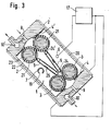
- Fig. 3 einen Längsschnitt der Entwicklungsvorrichtung nach Fig. 1, bei der die Entwicklungskammer eine Schrägstellung und der Verdampfer eine Senkrechtstellung einnimmt.
- 1 is a longitudinal section of the developing device from the developing chamber and evaporator,
- Fig. 2 in cross section the developing device according to Fig. 1, and
- Fig. 3 is a longitudinal section of the developing device according to Fig. 1, in which the development chamber is in an inclined position and the evaporator is in a vertical position.
In den Figuren 1 und 2 ist eine Vorrichtung zur Ausübung des erfindungsgemäßen Verfahrens dargestellt, die im wesentlichen aus einer Entwicklungskammer 1 und einem seitlich an dieser angebrachten Verdampfer 11, wie er in Fig. 2 im Schnitt gezeigt ist, besteht. Das Kopiermaterial tritt durch einen Eingabeschlitz 8 in die Entwicklungskammer 1 ein und verläßt diese durch einen Ausgabeschlitz 9. Die Entwicklungskammer 1 ist durch ein angetriebenes Paar von Einlaufwalzen 21 und durch ein ebenfalls angetriebenes Paar von Auslaufwalzen 3 gegen die äußere Atmosphäre weitgehend abgeschlossen. Mit den Einlaufwalzen 21 wirken Dichtlamellen 4' zur äußeren Atmosphäre zusammen. Ebenso liegen Dichtlamellen 4 an den Auslaufwalzen 3 an und dichten diese weitgehend gegenüber der äußeren Atmosphäre ab. Die Walzen 21 und 3 bestehen jeweils aus einem Metallkern 22, der einen Belag 23 aus ammoniak-und hitzebeständigem Silikonkautschuk trägt. Dieser Silikonkautschuk ist bis zu 170° C weitgehend ammoniak- und wärmefest und besitzt gegenüber den üblichen Gummimischungen für derartige Beläge, die sich nach einiger Zeit zersetzen und verhärten, eine erheblich erhöhte Lebensdauer. Die Dichtlamellen 4, 4' bestehen beispielsweise aus 0,05 mm starken FederstahlFIGS. 1 and 2 show a device for carrying out the method according to the invention, which essentially consists of a development chamber 1 and an evaporator 11 which is attached to the side thereof, as shown in section in FIG. 2. The copying material enters the development chamber 1 through an input slot 8 and leaves it through an output slot 9. The development chamber 1 is largely sealed off from the outside atmosphere by a driven pair of
Claims (15)
Applications Claiming Priority (2)
| Application Number | Priority Date | Filing Date | Title |
|---|---|---|---|
| DE19792914774 DE2914774A1 (en) | 1979-04-11 | 1979-04-11 | METHOD AND DEVICE FOR DEVELOPING TWO-COMPONENT DIAZOCOPY MATERIAL |
| DE2914774 | 1979-04-11 |
Publications (2)
| Publication Number | Publication Date |
|---|---|
| EP0017864A1 EP0017864A1 (en) | 1980-10-29 |
| EP0017864B1 true EP0017864B1 (en) | 1982-11-17 |
Family
ID=6068128
Family Applications (1)
| Application Number | Title | Priority Date | Filing Date |
|---|---|---|---|
| EP80101782A Expired EP0017864B1 (en) | 1979-04-11 | 1980-04-03 | Method and apparatus for development of two-component diazotype material |
Country Status (4)
| Country | Link |
|---|---|
| US (1) | US4319826A (en) |
| EP (1) | EP0017864B1 (en) |
| JP (1) | JPS55143559A (en) |
| DE (2) | DE2914774A1 (en) |
Families Citing this family (11)
| Publication number | Priority date | Publication date | Assignee | Title |
|---|---|---|---|---|
| US4412731A (en) * | 1981-07-29 | 1983-11-01 | Ncr Corporation | High speed low temperature diazo processor |
| US4477166A (en) * | 1982-11-24 | 1984-10-16 | R. Funk And Co., Inc. | Diazo printer with improved ammonia supply system |
| JPS63141692A (en) * | 1986-12-03 | 1988-06-14 | Konica Corp | Method and device for evaporation and concentration treatment of waste photographic processing liquid |
| AU603400B2 (en) * | 1986-12-17 | 1990-11-15 | Konica Corporation | Method of treating photographic process waste liquor through concentration by evaporation and apparatus therefor |
| AU608579B2 (en) * | 1987-03-24 | 1991-04-11 | Konica Corporation | Apparatus and method for treating photographic process waste liquor through concentration by evaporation |
| JPH01193558A (en) * | 1988-01-28 | 1989-08-03 | Matsushita Electric Ind Co Ltd | Gas-burning hot air heater |
| JPH01314851A (en) * | 1988-06-15 | 1989-12-20 | Matsushita Electric Ind Co Ltd | Quick space heating controller for space heater |
| JPH01314852A (en) * | 1988-06-15 | 1989-12-20 | Matsushita Electric Ind Co Ltd | Quick space heating controller for space heater |
| JPH0233567A (en) * | 1988-07-20 | 1990-02-02 | Matsushita Electric Ind Co Ltd | Hot air heater |
| JPH07208736A (en) * | 1994-10-11 | 1995-08-11 | Hitachi Home Tec Ltd | Warm air heater |
| JPH07198136A (en) * | 1994-10-11 | 1995-08-01 | Hitachi Home Tec Ltd | Hot-air heater |
Family Cites Families (12)
| Publication number | Priority date | Publication date | Assignee | Title |
|---|---|---|---|---|
| DE611428C (en) * | 1932-01-20 | 1935-03-30 | Sidney Harold Morse | Method and apparatus for developing photosensitive layers |
| DE862259C (en) * | 1950-06-26 | 1953-01-08 | Ozalid Co Ltd | Method and device for developing photographic substrates by means of an evaporated developer solution |
| US4062031A (en) * | 1972-09-09 | 1977-12-06 | Hoechst Aktiengesellschaft | Apparatus for producing a developer medium for diazotype materials |
| DE2244422C3 (en) * | 1972-09-09 | 1980-11-06 | Hoechst Ag, 6000 Frankfurt | Method and device for vaporizing a developer medium in developing devices for diazotype materials |
| HU168796B (en) * | 1973-04-25 | 1976-07-28 | ||
| DE2363821A1 (en) * | 1973-12-21 | 1975-06-26 | Hoechst Ag | DEVICE FOR VAPORATING A DEVELOPER MEDIUM IN DEVELOPMENT DEVICES FOR DIAZOTYPE MATERIALS |
| DE2534352C3 (en) * | 1975-08-01 | 1979-05-10 | Hoechst Ag, 6000 Frankfurt | Process for the dry development of non-heat developable two-component diazotype materials |
| DE2613331C2 (en) * | 1976-03-29 | 1981-06-25 | Hoechst Ag, 6230 Frankfurt | Device for generating ammonia-containing developer gas for the development device of a diazo copier |
| DE2623982B2 (en) * | 1976-05-28 | 1978-10-12 | Hoechst Ag, 6000 Frankfurt | Process for making diazotype copies |
| DE2659486C2 (en) * | 1976-12-30 | 1978-12-07 | Hoechst Ag, 6000 Frankfurt | Developing device for developing sheets of diazo copy material |
| DE7702598U1 (en) * | 1977-01-29 | 1977-05-18 | Hoechst Ag, 6000 Frankfurt | EVAPORATOR FOR GENERATING DEVELOPMENT GAS CONTAINING AMMONIA GAS FROM AMMONIA WATER FOR THE DEVELOPMENT OF DIAZO COPY MATERIAL |
| DE2726240C2 (en) * | 1977-06-10 | 1978-10-26 | Hoechst Ag, 6000 Frankfurt | Process and device for the dry development of two-component diazotype material |
-
1979
- 1979-04-11 DE DE19792914774 patent/DE2914774A1/en not_active Withdrawn
-
1980
- 1980-04-03 EP EP80101782A patent/EP0017864B1/en not_active Expired
- 1980-04-03 DE DE8080101782T patent/DE3061090D1/en not_active Expired
- 1980-04-04 US US06/137,416 patent/US4319826A/en not_active Expired - Lifetime
- 1980-04-11 JP JP4695180A patent/JPS55143559A/en active Granted
Also Published As
| Publication number | Publication date |
|---|---|
| JPS6252848B2 (en) | 1987-11-07 |
| DE3061090D1 (en) | 1982-12-23 |
| US4319826A (en) | 1982-03-16 |
| DE2914774A1 (en) | 1980-10-30 |
| JPS55143559A (en) | 1980-11-08 |
| EP0017864A1 (en) | 1980-10-29 |
Similar Documents
| Publication | Publication Date | Title |
|---|---|---|
| EP0017864B1 (en) | Method and apparatus for development of two-component diazotype material | |
| DE68902548T2 (en) | DRYER FOR A RAILWAY. | |
| DE2366006A1 (en) | DEVICE FOR THE RECOVERY OF VAPORATED DEVELOPER LIQUID | |
| DE1977683U (en) | DEVICE FOR DEVELOPING LIGHT SENSITIVE PAPERS. | |
| CH395155A (en) | Process for developing an electrostatic latent image and apparatus for carrying out the process | |
| DE2522933C3 (en) | Apparatus for developing photosensitive material | |
| DE2224243A1 (en) | Solvent recovery | |
| DE2514175C3 (en) | Developing device for photocopying machines | |
| DE2126239C3 (en) | Electrophotographic copier | |
| DE19755584A1 (en) | Method and device for fixing toner images | |
| DE2639778B2 (en) | Developing device for a diazo copier | |
| DE939791C (en) | Copying and developing device | |
| EP0000049B1 (en) | Process and device for the dry development of a two-component diazotype material | |
| DE1797357C3 (en) | Apparatus for developing a latent image on a heat-developable, easily damaged, photosensitive layer on a support in the form of a film | |
| DE2206451A1 (en) | Apparatus and method for exposing and developing photosensitive sheet-like materials | |
| DE3041536A1 (en) | DEVICE FOR DEVELOPING EXPOSED COPY MATERIAL | |
| EP0049441B1 (en) | Method of continuously applying a dye bath to a wet textile sheet material | |
| DE862259C (en) | Method and device for developing photographic substrates by means of an evaporated developer solution | |
| DE7315281U (en) | DEVICE FOR THE DEVELOPMENT OF IN PARTICULAR PHOTOCOPY-FORMING MATERIAL | |
| DE2623982A1 (en) | METHOD AND DEVICE FOR THE PRODUCTION OF LIGHT BREAKS WITH TWO-COMPONENT DIAZOTYPE MATERIAL | |
| DE2534352A1 (en) | METHOD AND DEVICE FOR DRY DEVELOPMENT OF TWO-COMPONENT DIAZOTYPE MATERIAL, IN PARTICULAR OF MICROFILM DUPLICATING FILM | |
| DE2307047A1 (en) | DEVICE FOR TREATMENT OF TEXTILE MATERIALS | |
| DE1447848A1 (en) | Method and apparatus for making copies | |
| DE1958767A1 (en) | Method for drying a moisture-containing tape and apparatus for carrying out the method | |
| AT346799B (en) | POETRY |
Legal Events
| Date | Code | Title | Description |
|---|---|---|---|
| PUAI | Public reference made under article 153(3) epc to a published international application that has entered the european phase |
Free format text: ORIGINAL CODE: 0009012 |
|
| AK | Designated contracting states |
Designated state(s): DE FR GB NL |
|
| 17P | Request for examination filed |
Effective date: 19810326 |
|
| GRAA | (expected) grant |
Free format text: ORIGINAL CODE: 0009210 |
|
| AK | Designated contracting states |
Designated state(s): DE FR GB NL |
|
| REF | Corresponds to: |
Ref document number: 3061090 Country of ref document: DE Date of ref document: 19821223 |
|
| ET | Fr: translation filed | ||
| PGFP | Annual fee paid to national office [announced via postgrant information from national office to epo] |
Ref country code: FR Payment date: 19920306 Year of fee payment: 13 |
|
| PGFP | Annual fee paid to national office [announced via postgrant information from national office to epo] |
Ref country code: GB Payment date: 19920312 Year of fee payment: 13 |
|
| PGFP | Annual fee paid to national office [announced via postgrant information from national office to epo] |
Ref country code: NL Payment date: 19920430 Year of fee payment: 13 |
|
| PGFP | Annual fee paid to national office [announced via postgrant information from national office to epo] |
Ref country code: DE Payment date: 19920611 Year of fee payment: 13 |
|
| PG25 | Lapsed in a contracting state [announced via postgrant information from national office to epo] |
Ref country code: GB Effective date: 19930403 |
|
| PG25 | Lapsed in a contracting state [announced via postgrant information from national office to epo] |
Ref country code: NL Effective date: 19931101 |
|
| GBPC | Gb: european patent ceased through non-payment of renewal fee |
Effective date: 19930403 |
|
| NLV4 | Nl: lapsed or anulled due to non-payment of the annual fee | ||
| PG25 | Lapsed in a contracting state [announced via postgrant information from national office to epo] |
Ref country code: FR Effective date: 19931229 |
|
| PG25 | Lapsed in a contracting state [announced via postgrant information from national office to epo] |
Ref country code: DE Effective date: 19940101 |
|
| REG | Reference to a national code |
Ref country code: FR Ref legal event code: ST |
|
| PLBE | No opposition filed within time limit |
Free format text: ORIGINAL CODE: 0009261 |
|
| STAA | Information on the status of an ep patent application or granted ep patent |
Free format text: STATUS: NO OPPOSITION FILED WITHIN TIME LIMIT |