EP0017553B1 - Système de visualisation d'images numériques, notamment pour leur reproduction par photographie, comportant un dispositif de correction des demi-teintes - Google Patents
Système de visualisation d'images numériques, notamment pour leur reproduction par photographie, comportant un dispositif de correction des demi-teintes Download PDFInfo
- Publication number
- EP0017553B1 EP0017553B1 EP80400387A EP80400387A EP0017553B1 EP 0017553 B1 EP0017553 B1 EP 0017553B1 EP 80400387 A EP80400387 A EP 80400387A EP 80400387 A EP80400387 A EP 80400387A EP 0017553 B1 EP0017553 B1 EP 0017553B1
- Authority
- EP
- European Patent Office
- Prior art keywords
- digital
- memory
- cathode ray
- images
- ray tube
- Prior art date
- Legal status (The legal status is an assumption and is not a legal conclusion. Google has not performed a legal analysis and makes no representation as to the accuracy of the status listed.)
- Expired
Links
Images

Classifications
-
- H—ELECTRICITY
- H04—ELECTRIC COMMUNICATION TECHNIQUE
- H04N—PICTORIAL COMMUNICATION, e.g. TELEVISION
- H04N1/00—Scanning, transmission or reproduction of documents or the like, e.g. facsimile transmission; Details thereof
- H04N1/40—Picture signal circuits
- H04N1/407—Control or modification of tonal gradation or of extreme levels, e.g. background level
- H04N1/4076—Control or modification of tonal gradation or of extreme levels, e.g. background level dependent on references outside the picture
-
- G—PHYSICS
- G06—COMPUTING OR CALCULATING; COUNTING
- G06T—IMAGE DATA PROCESSING OR GENERATION, IN GENERAL
- G06T5/00—Image enhancement or restoration
- G06T5/90—Dynamic range modification of images or parts thereof
- G06T5/92—Dynamic range modification of images or parts thereof based on global image properties
-
- G—PHYSICS
- G06—COMPUTING OR CALCULATING; COUNTING
- G06T—IMAGE DATA PROCESSING OR GENERATION, IN GENERAL
- G06T2207/00—Indexing scheme for image analysis or image enhancement
- G06T2207/10—Image acquisition modality
- G06T2207/10072—Tomographic images
Definitions
- the present invention relates to a digital image display system usable for example in computed tomography comprising a device for correcting halftones.
- This correction device is particularly useful when the displayed images, from digital images stored in a memory, have to be recorded by photography on films.
- a digital image obtained by means which will not be described here, is, at least in part, stored in a memory, in the form of a certain number of digital words, each word corresponding to a point of the image and being able to have one of N values.
- the digital images are extracted word by word from memory and are, if necessary after processing, converted in a digital analog converter into a signal which is shaped and applied to a display monitor with cathode ray tube.
- the non-linearity of the cathode ray tube partly compensates for the non-linearity of the response curve of the eye. This is however no longer true when the cathode ray tube is "seen" by the film of a camera.
- the films used indeed have sensitometric characteristics which are not linear as a function of the level of the image, all the more so since the films used are generally not reversible and it is necessary to carry out an electrical inversion. video signal. This inversion can be done either in the monitor itself if it is only intended for photographic use or, if it is a standard monitor, by a signal inversion circuit placed immediately before the input of the monitor.
- the object of the present invention is a device for correcting this type of phenomenon, which makes it possible on the one hand to carry out the correction as a function of the different non-linearities of the detectors sensitive to the image obtained on the cathode ray tube, and on the other hand allows to store in the memory the information relating to the digital image in a raw form.
- a correction device in accordance with the invention comprises at least one linearization memory containing a table for transposing the information that it receives, a function of the non-linearities to be corrected, this memory performing the correction as and when it receives the information and transmits it to the digital to analog converter.
- the raw information is kept intact, while the information transmitted to the digital analog converter is corrected "on the fly", that is to say as and when it is necessary to develop on the monitor viewing the image to be observed.
- the invention relates to a digital image display system of the type comprising at least one cathode ray tube for the direct observation of said images and a photographic means for taking a particular image on said cathode ray tube at a chosen time, a refresh memory in which are constantly updated raw digital information representative of a succession of images and digital-analog conversion means connected between said refresh memory and said cathode ray tube, characterized in that it includes a linearization memory, known per se, inserted, at least when taking a photographic photograph, at a point in the digital processing chain between the output of said refresh memory and the input of said digital-analog converter, said memory being adapted to the type of film used .
- This correction device is particularly useful when it comes to storing on films the images obtained on the display monitor.
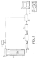
- FIG. 1 shows the essential elements of a system for viewing digital images in the case for example of viewing CT images, constituting the prior art of the present invention.
- the digital images obtained by means well known now, each consist of P digital words arranged, sequentially for example, in a memory schematically represented at 1 in FIG. 1.
- the P digital words of each image which correspond to the P points analyzed can each have one of N values corresponding to the N levels to be represented.
- the digital system used is generally the binary system, the N possible values of each point will be coded on for example p bits.
- the memory 1 shown here is a so-called refresh memory. It therefore contains the P digital words which must periodically be sent to the display monitor so that the image on this monitor remains permanently despite the non-remanence of the cathode ray type. Since the display monitor 2 is a television type receiver, the main feature of the refresh memory shown in 1 is that it can give access to all the values stored therein in a time less than or equal to the duration of a television frame. .
- a buffer memory 5 can for example contain up to one image line.
- An image is in fact classically made up of words arranged in rows and columns.
- Each value leaving the processing module 7 is then converted into an analog signal in the digital to analog converter 6, and shaped, in synchronism with the clock 4, in shaping circuits 8 to form a video signal which can be used by a or several televisions that can be used for visual observation and / or photography.
- the video signal delivered by the shaping circuits 8 is here applied on the one hand to a monitor 2 on which the image can be directly observed, and on the other hand to a monitor whose cathode ray tube 9 is " seen "by a camera 10 comprising a film 11 on which the image will be recorded.
- Figure 2 shows in block diagram the block diagram of a display system comprising a correction device according to the invention.
- FIGS. 2 to 4 the same references as those in FIG. 1 correspond to the same elements.
- the display system is not necessarily used in a CT scanner; this is why the processing module 7 has not been represented, described on the occasion of FIG. 1.
- the correction device of the invention can be used in applications other than computed tomography, and in particular in applications where processing is not necessary before converting the digital image; the invention can in particular be used each time it is a question of viewing medical images, obtained for example by ultrasound.
- the invention essentially consists, knowing the nonlinearity curve which affects the image between the output of the shaping circuit 8 and the perception of this image by the detector which "sees" the screen of the cathode ray tube. used for visualization, whether this detector is the eyes of an observer, or whether it is a photographic film, to have, after the refresh memory and the associated buffer memory, and before the digital analog converter 6, a linearization memory which will allow each digital word transmitted to the digital analog converter to be corrected, as this transfer takes place.
- This memory can also provide the signal inversion function necessary when non-invertible films are used, avoiding having to do this later on the analog signal.
- the linearization memory 20 can be for example a memory of the random access type (RAM) previously loaded, or of the read only type (ROM) containing a linearization table.
- This linearization table includes N positions if each word of the digital image can have N different values; the addresses of these N positions are the N values that each image point can take while their values are the most N corrected values to keep comote of the aforementioned non-linearity.
- the various image values arrive in the linearization memory 20, they are automatically directed to the correct address and interpreted as an address to extract from the table the value corrected as a function of the non-linearity which their matches. These corrected values are in turn sent, as the correction is made, to the digital analog converter 6.
- the role of the linearization memory 20 is absolutely fundamental when the screen of the cathode ray tube is seen by a film camera. It indeed makes it possible to obtain a sensitometric curve correcting exactly that of the film, and this whatever the type of film.
- FIG. 3 represents the block diagram of a display system according to the invention in an application where it is desired to be able to observe the image displayed either directly on a television type monitor 2, or by means of a film 11 "looking" at a cathode ray tube 9.
- the example of application shown here also includes a processing module 7 such as that described on the occasion of FIG. 1.
- This processing module when it acts as a system for viewing computed tomography images, in particular performs the aforementioned windowing operation and transforms the digital words of p bits into digital words of q bits.
- the linearization memory 20 is connected in the digital information processing chain, between the processing module 7 and the digital analog converter 6. It contains a linearization table adapted to the film 11.
- a switch symbolically represented at 21 , allows to connect or not the linearization memory 20 in the display chain.
- the switch 21 When the switch 21 is in position (a) the linearization memory 20 is on, and the correction is carried out. In this case the image recorded on the film 11 is correct, while that seen on the monitor 2 is not.
- the linearization memory 20 indeed contains corrections intended for the film 11 and not for eye observation.
- the switch 21 When, on the contrary, one no longer wishes to record the image on film, but to watch it directly on the monitor 2, the switch 21 is set to position (b) so as to delete the linearization memory from the chain.
- the control of this switch can, for example, be controlled by the triggering of the camera, the image being linearized for a time equal to or slightly greater than the exposure time.
- FIG. 4 represents a variant of the system of FIG. 3, in which the two observations, direct on the monitor 2, and via a film 11, can be carried out simultaneously.
- the display chain is divided, at the output of the processing module 7, into two channels.
- a first channel which is the photo channel, includes the linearization memory 20 which sends its information to a first digital analog converter 61.
- the values corrected according to the film 11 are, after shaping in a first circuit 81, sent to the tube 9 for recording on film 11.
- the second channel does not have a linearization memory since it has been said that this is not essential, and comprises a second digital analog converter 62 which supplies a second shaping circuit 82 whose output signals are applied to the display monitor 2.
- the correction device of the invention makes it possible to use different types of film while making the different corresponding corrections correctly. It is clear that to obtain different corrections in this way, it is necessary to be able to change the linearization table contained in the memory 20. Different variants are possible for this.
- the linearization memory 20 is constituted by a module easily interchangeable by the user, for example pluggable. So we change the module every time we change the film.
- Another variant consists in immediately placing the various modules relating to all the types of film likely to be used, the operator selecting by voluntary means (command by selector, buttons, or by order in alpha-numeric characters struck on a keyboard connected to the computer managing the assembly) the module adapted to the type of film used.
- Yet another variant consists in making this selection automatic. This can be done by means actuated by the cassette containing the film, such as a switch operated by a pin or a notch, or an optical selector (bar code for example), or even to avoid any risk, to make these means integral with the film itself: notch on one side of the film for example, the detection being able to remain mechanical or optical in a wavelength band not likely to impress the film (for example infrared).
Landscapes
- Engineering & Computer Science (AREA)
- Multimedia (AREA)
- Signal Processing (AREA)
- Physics & Mathematics (AREA)
- General Physics & Mathematics (AREA)
- Theoretical Computer Science (AREA)
- Apparatus For Radiation Diagnosis (AREA)
- Closed-Circuit Television Systems (AREA)
- Controls And Circuits For Display Device (AREA)
Applications Claiming Priority (2)
| Application Number | Priority Date | Filing Date | Title |
|---|---|---|---|
| FR7907389A FR2452221A1 (fr) | 1979-03-23 | 1979-03-23 | Dispositif de correction des demi-teintes dans un systeme de visualisation d'images numeriques, notamment pour leur reproduction par photographie, et systeme de visualisation comportant un tel dispositif |
| FR7907389 | 1979-03-23 |
Publications (2)
| Publication Number | Publication Date |
|---|---|
| EP0017553A1 EP0017553A1 (fr) | 1980-10-15 |
| EP0017553B1 true EP0017553B1 (fr) | 1984-02-15 |
Family
ID=9223494
Family Applications (1)
| Application Number | Title | Priority Date | Filing Date |
|---|---|---|---|
| EP80400387A Expired EP0017553B1 (fr) | 1979-03-23 | 1980-03-21 | Système de visualisation d'images numériques, notamment pour leur reproduction par photographie, comportant un dispositif de correction des demi-teintes |
Country Status (3)
| Country | Link |
|---|---|
| EP (1) | EP0017553B1 (enExample) |
| DE (1) | DE3066540D1 (enExample) |
| FR (1) | FR2452221A1 (enExample) |
Families Citing this family (6)
| Publication number | Priority date | Publication date | Assignee | Title |
|---|---|---|---|---|
| US4496968A (en) * | 1981-07-14 | 1985-01-29 | Crosfield Electronics Limited | Reproduction of colored images |
| US4617592A (en) * | 1982-03-11 | 1986-10-14 | Crosfield Electronics Limited | Video retouching system |
| JPS6064386A (ja) * | 1983-09-20 | 1985-04-12 | 株式会社東芝 | 画像表示装置 |
| US4829584A (en) * | 1985-03-26 | 1989-05-09 | Dainippon Screen Mfg. Co., Ltd. | Image input system |
| DE3750013T2 (de) | 1986-10-20 | 1994-09-29 | Fuji Photo Film Co Ltd | Laserstrahlabtastverfahren und -vorrichtung. |
| GB8800503D0 (en) * | 1988-01-11 | 1988-02-10 | Crosfield Electronics Ltd | Apparatus for generating two-dimensional coloured display |
-
1979
- 1979-03-23 FR FR7907389A patent/FR2452221A1/fr active Granted
-
1980
- 1980-03-21 EP EP80400387A patent/EP0017553B1/fr not_active Expired
- 1980-03-21 DE DE8080400387T patent/DE3066540D1/de not_active Expired
Non-Patent Citations (1)
| Title |
|---|
| "Digital Image Processing" W.K. Pratt publié en 1978 par Wiley-Interscience,pages 447-452 * |
Also Published As
| Publication number | Publication date |
|---|---|
| FR2452221A1 (fr) | 1980-10-17 |
| DE3066540D1 (en) | 1984-03-22 |
| FR2452221B1 (enExample) | 1983-04-29 |
| EP0017553A1 (fr) | 1980-10-15 |
Similar Documents
| Publication | Publication Date | Title |
|---|---|---|
| EP1415275B1 (fr) | Procede et systeme pour fournir des informations formatees a des moyens de traitement d'images | |
| WO1987004530A1 (fr) | Dispositif de traitement d'image pour le controle de la fonction de transfert d'un systeme optique | |
| FR2594241A1 (fr) | Processeur d'affichage de donnees sur un ecran d'affichage et procede d'affichage de donnees mettant en oeuvre ce dispositif | |
| FR2513836A1 (enExample) | ||
| FR2605771A1 (fr) | Appareil de traitement de donnees d'images | |
| WO1991012690A1 (fr) | Dispositif d'augmentation de dynamique d'une camera | |
| EP0067083B1 (fr) | Dispositif de correction des informations couleur fournies par une caméra de télévision, en vue d'améliorer la perception des images | |
| EP0176389B1 (fr) | Dispositif de correction de signaux vidéo pour système d'acquisition et d'analyse de signaux rapides utilisant une caméra à fente | |
| FR2718547A1 (fr) | Procédé et appareil pour afficher une image obtenue par rayons X. | |
| FR2863441A1 (fr) | Systeme et procede pour dispositif photographique numerique effectuant une visualisation auto-etalonnee en reproduction | |
| EP0017553B1 (fr) | Système de visualisation d'images numériques, notamment pour leur reproduction par photographie, comportant un dispositif de correction des demi-teintes | |
| EP2011329B1 (fr) | Procédé de traitement d'un phénomène d'éclairement relatif sur une image numérique et système de traitement associé | |
| EP0200623A1 (fr) | Installation de radiologie | |
| EP0019518A1 (fr) | Dispositif de commande automatique de la fonction de transfert d'un système de transmission vidéofréquence en vue d'améliorer la perception des images | |
| EP0222641B1 (fr) | Nouveaux dispositifs d'obturation électronique | |
| EP1351498A2 (fr) | Procédé de traitement en temps réel d'un signal représentatif d'une image | |
| FR2476952A1 (fr) | Generateur de signaux de base et de signaux de test de television et systeme comportant un tel dispositif | |
| EP0524842A1 (fr) | Dispositif temps réel de présentation d'images de type télévision sur un écran de visualisation | |
| FR2463429A1 (fr) | Installation de prise et de developpement de cliches radiographiques | |
| EP0236157A1 (fr) | Système de lecture rapide d'un capteur optique matriciel à transfert de charges organisé en transfert de trame monocoup pour la détection vidéo d'images brèves | |
| EP0108689B1 (fr) | Dispositif de superposition d'informations synthétiques sur des informations cartographiques | |
| EP1787585B1 (fr) | Procédé d'asservissement d'une source de rayons X d'un dispositif de radiographie | |
| FR2472799A1 (fr) | Dispositif a memoire pour la visualisation d'informations analogiques et numeriques | |
| CA1263761A (fr) | Dispositif de traitement d'image pour le controle de la fonction de transfert d'un systeme optique | |
| FR2687265A1 (fr) | Dispositif de prise de vue electronique a haute dynamique et procede de prise de vue de scenes tres contrastees. |
Legal Events
| Date | Code | Title | Description |
|---|---|---|---|
| PUAI | Public reference made under article 153(3) epc to a published international application that has entered the european phase |
Free format text: ORIGINAL CODE: 0009012 |
|
| AK | Designated contracting states |
Designated state(s): DE GB NL |
|
| 17P | Request for examination filed |
Effective date: 19801120 |
|
| GRAA | (expected) grant |
Free format text: ORIGINAL CODE: 0009210 |
|
| AK | Designated contracting states |
Designated state(s): DE GB NL |
|
| REF | Corresponds to: |
Ref document number: 3066540 Country of ref document: DE Date of ref document: 19840322 |
|
| PLBE | No opposition filed within time limit |
Free format text: ORIGINAL CODE: 0009261 |
|
| STAA | Information on the status of an ep patent application or granted ep patent |
Free format text: STATUS: NO OPPOSITION FILED WITHIN TIME LIMIT |
|
| 26N | No opposition filed | ||
| GBPC | Gb: european patent ceased through non-payment of renewal fee | ||
| PG25 | Lapsed in a contracting state [announced via postgrant information from national office to epo] |
Ref country code: GB Effective date: 19881118 |
|
| PGFP | Annual fee paid to national office [announced via postgrant information from national office to epo] |
Ref country code: NL Payment date: 19930331 Year of fee payment: 14 |
|
| PG25 | Lapsed in a contracting state [announced via postgrant information from national office to epo] |
Ref country code: NL Effective date: 19941001 |
|
| NLV4 | Nl: lapsed or anulled due to non-payment of the annual fee | ||
| PGFP | Annual fee paid to national office [announced via postgrant information from national office to epo] |
Ref country code: DE Payment date: 19990305 Year of fee payment: 20 |