EP0016534A1 - Passerelle pour toitures - Google Patents
Passerelle pour toitures Download PDFInfo
- Publication number
- EP0016534A1 EP0016534A1 EP80300469A EP80300469A EP0016534A1 EP 0016534 A1 EP0016534 A1 EP 0016534A1 EP 80300469 A EP80300469 A EP 80300469A EP 80300469 A EP80300469 A EP 80300469A EP 0016534 A1 EP0016534 A1 EP 0016534A1
- Authority
- EP
- European Patent Office
- Prior art keywords
- walkway
- roof
- tread portion
- gutter
- plastics moulding
- Prior art date
- Legal status (The legal status is an assumption and is not a legal conclusion. Google has not performed a legal analysis and makes no representation as to the accuracy of the status listed.)
- Withdrawn
Links
Images


Classifications
-
- E—FIXED CONSTRUCTIONS
- E04—BUILDING
- E04D—ROOF COVERINGS; SKY-LIGHTS; GUTTERS; ROOF-WORKING TOOLS
- E04D13/00—Special arrangements or devices in connection with roof coverings; Protection against birds; Roof drainage; Sky-lights
- E04D13/12—Devices or arrangements allowing walking on the roof or in the gutter
-
- D—TEXTILES; PAPER
- D21—PAPER-MAKING; PRODUCTION OF CELLULOSE
- D21H—PULP COMPOSITIONS; PREPARATION THEREOF NOT COVERED BY SUBCLASSES D21C OR D21D; IMPREGNATING OR COATING OF PAPER; TREATMENT OF FINISHED PAPER NOT COVERED BY CLASS B31 OR SUBCLASS D21G; PAPER NOT OTHERWISE PROVIDED FOR
- D21H13/00—Pulp or paper, comprising synthetic cellulose or non-cellulose fibres or web-forming material
- D21H13/10—Organic non-cellulose fibres
- D21H13/12—Organic non-cellulose fibres from macromolecular compounds obtained by reactions only involving carbon-to-carbon unsaturated bonds
- D21H13/14—Polyalkenes, e.g. polystyrene polyethylene
-
- D—TEXTILES; PAPER
- D21—PAPER-MAKING; PRODUCTION OF CELLULOSE
- D21H—PULP COMPOSITIONS; PREPARATION THEREOF NOT COVERED BY SUBCLASSES D21C OR D21D; IMPREGNATING OR COATING OF PAPER; TREATMENT OF FINISHED PAPER NOT COVERED BY CLASS B31 OR SUBCLASS D21G; PAPER NOT OTHERWISE PROVIDED FOR
- D21H13/00—Pulp or paper, comprising synthetic cellulose or non-cellulose fibres or web-forming material
- D21H13/36—Inorganic fibres or flakes
- D21H13/46—Non-siliceous fibres, e.g. from metal oxides
- D21H13/50—Carbon fibres
-
- D—TEXTILES; PAPER
- D21—PAPER-MAKING; PRODUCTION OF CELLULOSE
- D21H—PULP COMPOSITIONS; PREPARATION THEREOF NOT COVERED BY SUBCLASSES D21C OR D21D; IMPREGNATING OR COATING OF PAPER; TREATMENT OF FINISHED PAPER NOT COVERED BY CLASS B31 OR SUBCLASS D21G; PAPER NOT OTHERWISE PROVIDED FOR
- D21H17/00—Non-fibrous material added to the pulp, characterised by its constitution; Paper-impregnating material characterised by its constitution
- D21H17/63—Inorganic compounds
- D21H17/67—Water-insoluble compounds, e.g. fillers, pigments
- D21H17/68—Water-insoluble compounds, e.g. fillers, pigments siliceous, e.g. clays
Definitions
- This invention is concerned with walkways, and in particular with a walkway composed of elements moulded from plastics material.
- the roof In the building of factories the roof is commonly constructed in a form which consists of a series of ridges separated by valleys, a gutter being provided along the bottom of each valley.
- the roof cladding is frequently asbestos cement sheet with glass roof lights.
- gutters For maintenance purposes it is necessary for access to be gained to areas of the roof from time to time, and on such occasions the gutters form a convenient walkway across the roof, ladders being fixed to give access to the sloping areas of the roof.
- the gutters themselves are often constructed from asbestos-cement and are liable to damage if walked upon. Also they tend to be narrow so that a person walking in them is liable to catch his or her ankles on the edges of the roof cladding sheets.
- the present invention aims to provide an alternative for such wooden walkways which is safe and rotproof.
- a roof walkway which comprises a plurality of linked elongate elements, each said element including a tread portion comprising a single substantially rigid plastics moulding of a form providing drainage holes therein and a tread surface comprising a high friction material.
- each element is individually capable of being supported on one or more support members in an elevated position relative to the roof, for which purpose said tread portion has moulded into it location means for said support member.
- a roof walkway element includes a tread portion comprising a single substantially rigid plastics moulding of a form providing drainage holes therein, and a tread surface comprising a high friction material, and includes also location means in said Cread portion for at least one support member to support said tread portion out of a gutter.
- the plastics moulding may, for example, be of a structural foam such as foamed polypropylene, and has a wall thickness and form appropriate to support the weight of persons standing and working from it.
- the support member is slender in cross-section at right angles to the intended direction of the walkway, at least-, such as to allow adequate flow capacity in a gutter when in use,
- the support member may be'a. single moulding but is preferably detachable, and preferably a plurality of moulded legs are used, with various optional locating sockets for such legs in said tread portion.
- no support member may be required, or the support member may simply be a square foot or block.
- the walkway includes a means for attachment to the roof. If no support member is provided the lower face of the plastic moulding forming the tread portion is free of protrusions which could damage the flat roof.
- Means of attachment to the flat roof may be provided separately, for example metal or plastics brackets shaped to hook over the plastics moulding and be fixed to the roof.
- the high friction material could be a coating on the appropriate surfaces of the tread portion, but is preferably a compounded high friction material based on an elastomeric binder with one or more abrasive fillers and used in the form of moulded inserts attached to the tread portion, or held in sockets moulded into the tread portion.
- the walkway elements may be linked by means of protruding lugs locking into corresponding sockets in adjacent elements.
- the normal linkage is end to end, although to facilitate stable walkways of more than one element's width means may be provided for lateral linkages between elements also-
- the elements may be lined by means of clips which locate in sockets moulded into one of the surfaces of the element. Such clips.may be of plastics or of metal.
- the walkway elements are suitable for use both in a gutter or on a flat roof.
- a preferred tread portion comprises a rectangular plastics moulding in the form of an inverted tray, having openings for drainage purposes, a plurality of locting sockets for support members on its underside to provide alternative positions, a plurality of sockets for friction material inserts on the upperside to provide.the tread surface, and sockets for linking purposes at the corners and the mid points of the longer sides of the moulding.
- the-walkway has fixing means to engage the roof and prevent movement of the walkway elements away from the roof when in use.
- a suitable fixing means is a bracket which can be engaged in an opening in the tread portion and with the roof, either behind the roof edge or on protrusions such as the ends of the U-bolts used to attach roofing panels to the roof structure beneath them.
- edges of the tread portion of the element are chamfered on their lower sides which is to rest on a roof.
- the preferred support members are legs with foot portions which have a slim shape in one direction to minimise obstruction of water flow in a gutter and a wide footprint in the other direction to spread the load of the walkway along the bottom of the gutter.
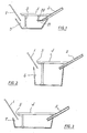
- Figure 1 shows a roof gutter arrangement in which a 60° roof elevation 1 of glass roof lights, and a 30° roof elevation 2 of corrugated asbestos cement slope down to a valley-type gutter 3.
- a walkway element consisting of a tread portion 4 and legs 5 is positioned with one edge of the tread portion 4 supported by the legs 5, the other supported on the 30° slope of the asbestos cement roof cladding.
- FIGs 2 and 3 show roofs of similar type but with two different sizes of box-type gutters 6 and 7 in place of the valley-type gutter 3 of Figure 1.
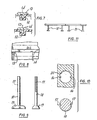
- the tread portion consists of a plastics moulding 8 with water drainage holes 9.
- the moulding is reinforced on its underside by transverse ribs 10 and longitudinal ribs 11 the transverse ribs also serving to provide location channels 12 for frictional elements 13 (see figures 8 and 7 respectively for detail of these).
- the frictional elements 13 are extrusions of T cross-section, the stem of the T being located in the channel 12, which is provided with inwardly protruding pips 14 to ensure a good interference fit.
- a connecting lug and socket to facilitate connection to the tread portion of an adjoining element of a walkway.
- leg wells 15 into which the legs are to be located.
- Various alternative leg positions are provided. including an optional position at the mid-length of the moulding.
- a leg well is shown in detail in figure 10, and it will be noticed that two inwardly projecting ribs 16 are provided in the otherwise circular well 20 to engage corresponding grooves 17 in the stem of each leg 18 to ensure correct orientation of the leg in the well.
- the legs 18 are provided with feet 19 as shown in figure 9, to spread the load on the bottom of the gutter, the feet being longer in one direction than the other as is apparent from the two side views of figure 9.
- the longer dimension of the foot is to be arranged along the length of the gutter, so that the foot presents minimum obstruction to flow of water along the gutter.
- the walkway element may be used free-standing in a gutter with legs supporting both edges if there is sufficient room in the gutter
- the walkway elements of this invention are relatively light, each being for example, about 1 metre long, are easily carried and may be laid across the roof successively from one end of the gutter, using one element as a platform from which to position the next. If desired they may be left up on the roof, but could, if desired be readily removed after maintenance of the roof had been carried out, and used again elsewhere.
- the legs are made removable the elements .can be stored in a minimum of storage space, the tread portions stacking on each other, when not in use on a roof.
- the legs may be moulded in plastics material, such as polyvinyl chloride, or polypropylene, although other materials could be used if so desired.
- plastics material such as polyvinyl chloride, or polypropylene, although other materials could be used if so desired.
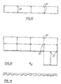
- FIGS. 12, 13 and 14 employ clips 21 to fasten together walkway elements either end to end (Figure 12) or end to end, side to side and end to side ( Figure 13).
- An arrangement such as that shown in Figure 13 can be used as a walkway on a felted flat roof.
- drainage can be provided on a flat roof by shaping the elements such that they allow passage beneath them both laterally and longitudinally.
- the elements shown in Figure 14 rest on the roof sledge fashion with only their longitudinal side portions in contact with the roof, thus assuming longitudinal drainage, and lateral drainage is provided by castellation of the longitudinal side portions which rest on the roof.
- the walkway element shown in Figure 15 consists of a tread portion 25 which is a plastics moulding in the form of an inverted tray having drainage apertures 26 extending through it and strengthening ribs, both lateral and longitudinal. on its underside.
- Strips of friction material 27 are provided on the tread surface, held in position by interference fit in slots in the tread portion 25.
- an opening 28 to receive an interconnection clip 29 (shown in Figure 17), and on each long side there is a further opening 30 which may be used to receive an interconnecting clip 29 or a flat roof clip 31 (shown in Figure 19).
- a plurality of sockets for support legs 32 (shown in Figure 18) the form of the interior of the sockets not being visible in Figure 15 but their blind ends show on the top surface of the tread portion 25- as the portions 33.
- Three rows each of three sockets are provided towards both long sides of the tread portion 25 to give alternative positions for the support legs 32.
- the support legs 32 as shown in figure 18 consist of a straight stem portion 34 having an approximately H-shaped cross section, and a foot portion 35 which is wider in one direction than the other and of a steamlined shape to minimise obstruction when it is used in a gutter.
- the stem portion 34 may be marked at intervals as shown at 36 to facilitate cutting down to a desired length to suit a particular gutter, when using the walkway in the manner shown in figure 1.
- the H-shaped cross section is to enable the socket for the support leg to be provided with a lug or lugs to ensure that the stem portion 34 can be inserted into its socket with the foot portion 35 only in the correct orientation.
- a suitable material for the support legs is a 10% glass filled U/V light protected polypropylene, and for the tread portion a foamed (0.7gm/ml density), U/V light protected polypropylene.
- the strips of friction material are preferably a compound of an oil and water resistant polymer, e.g. PVC or nitrile rubber or a mixture of both, with an abrasive filler.
- the tread portion 25 shown in figure 15 is provided with a row of holes 37 at each end to permit the use of roof brackets as shown in Figure 16.
- a roof bracket is shown diagrammaticaly in figure 1 to illustrate its mode of use, its function being to assist in keeping the walkway in its correct position in the gutter.
- the roof bracket shown in figure 16 consists of a pin 38 and bent strip 39, between which there is a 90° "fir tree" type fastening.
- the ratio of the lengths of the long and short sides is 2 to 1 in order to permit arrangements of several elements together, although the ratio 2 to 1 is not essential, 3 to 2 or 3 to 1 being other acceptable possibilities.
Applications Claiming Priority (4)
| Application Number | Priority Date | Filing Date | Title |
|---|---|---|---|
| GB7906176 | 1979-02-21 | ||
| GB7906176 | 1979-02-21 | ||
| GB7928388 | 1979-08-15 | ||
| GB7928388 | 1979-08-15 |
Publications (1)
| Publication Number | Publication Date |
|---|---|
| EP0016534A1 true EP0016534A1 (fr) | 1980-10-01 |
Family
ID=26270651
Family Applications (1)
| Application Number | Title | Priority Date | Filing Date |
|---|---|---|---|
| EP80300469A Withdrawn EP0016534A1 (fr) | 1979-02-21 | 1980-02-19 | Passerelle pour toitures |
Country Status (1)
| Country | Link |
|---|---|
| EP (1) | EP0016534A1 (fr) |
Cited By (4)
| Publication number | Priority date | Publication date | Assignee | Title |
|---|---|---|---|---|
| US4689927A (en) * | 1986-12-03 | 1987-09-01 | Usg Industries, Inc. | Walkway for a sloping rooftop |
| GB2412941A (en) * | 2004-04-07 | 2005-10-12 | Austin Reynolds Site Safety Lt | Elevated support structure providing working platform or fall arrest structure |
| WO2011070314A1 (fr) * | 2009-12-07 | 2011-06-16 | Kee Safety Limited | Module giron |
| GB2566252A (en) * | 2017-07-13 | 2019-03-13 | Av Coatings Ltd | Roof Board |
Citations (4)
| Publication number | Priority date | Publication date | Assignee | Title |
|---|---|---|---|---|
| GB570763A (en) * | 1943-10-26 | 1945-07-20 | Guest Keen & Nettlefolds Ltd | Improvements relating to floors, paving or roads |
| GB757385A (en) * | 1951-10-25 | 1956-09-19 | Moise Garti | Ground surface for athletic tracks and other uses |
| BE750281A (fr) * | 1970-05-12 | 1970-10-16 | Scheerlinck & Co S P R L F | Elements perfores pour revetements de sols. |
| GB1265625A (fr) * | 1969-11-21 | 1972-03-01 |
-
1980
- 1980-02-19 EP EP80300469A patent/EP0016534A1/fr not_active Withdrawn
Patent Citations (4)
| Publication number | Priority date | Publication date | Assignee | Title |
|---|---|---|---|---|
| GB570763A (en) * | 1943-10-26 | 1945-07-20 | Guest Keen & Nettlefolds Ltd | Improvements relating to floors, paving or roads |
| GB757385A (en) * | 1951-10-25 | 1956-09-19 | Moise Garti | Ground surface for athletic tracks and other uses |
| GB1265625A (fr) * | 1969-11-21 | 1972-03-01 | ||
| BE750281A (fr) * | 1970-05-12 | 1970-10-16 | Scheerlinck & Co S P R L F | Elements perfores pour revetements de sols. |
Cited By (6)
| Publication number | Priority date | Publication date | Assignee | Title |
|---|---|---|---|---|
| US4689927A (en) * | 1986-12-03 | 1987-09-01 | Usg Industries, Inc. | Walkway for a sloping rooftop |
| GB2412941A (en) * | 2004-04-07 | 2005-10-12 | Austin Reynolds Site Safety Lt | Elevated support structure providing working platform or fall arrest structure |
| GB2412941B (en) * | 2004-04-07 | 2009-08-05 | Austin Reynolds Site Safety Lt | Support structure |
| WO2011070314A1 (fr) * | 2009-12-07 | 2011-06-16 | Kee Safety Limited | Module giron |
| US9279256B2 (en) | 2009-12-07 | 2016-03-08 | Kee Safety Limited | Tread module |
| GB2566252A (en) * | 2017-07-13 | 2019-03-13 | Av Coatings Ltd | Roof Board |
Similar Documents
| Publication | Publication Date | Title |
|---|---|---|
| US5148644A (en) | Protective covering strip | |
| US5758456A (en) | Deck plank | |
| EP1211365B1 (fr) | Système de plancher | |
| US7434358B2 (en) | Panel assembly for underdeck drainage and other applications | |
| US4945697A (en) | Floor tile and floor | |
| US6594961B2 (en) | Deck plank extrusion and retaining clip | |
| CA1134587A (fr) | Bande de montage pour cloisons deplacables, avec latte d'accrochage pour tapis | |
| US6418693B2 (en) | Flooring assembly and fastener therefor | |
| US7503146B2 (en) | Covers, systems, and methods for covering outdoor deck components | |
| US5342141A (en) | Movable surface paving apparatus and method for using the same | |
| US7673425B2 (en) | Covers, systems, and methods for covering outdoor deck components | |
| US5546719A (en) | Waterproof decking method and apparatus | |
| US4566243A (en) | Plank grating assembly | |
| IE48811B1 (en) | Ridge batten bracket | |
| GB2202245A (en) | Tiling | |
| EP0016534A1 (fr) | Passerelle pour toitures | |
| US20110203200A1 (en) | Deck system | |
| GB2053309A (en) | Walkways and elements therefore | |
| GB2292396A (en) | Decking system | |
| US4541215A (en) | Snap-in ceiling system | |
| WO1998031894A1 (fr) | Tuile en ceramique a poser sur des poutres | |
| US20040231260A1 (en) | Under-deck grid-supported drainage system | |
| US20030029096A1 (en) | Under-deck shedding and drainage system | |
| JP3379063B2 (ja) | 換気棟瓦桟 | |
| US20020032990A1 (en) | Under-deck shedding and drainage system |
Legal Events
| Date | Code | Title | Description |
|---|---|---|---|
| PUAI | Public reference made under article 153(3) epc to a published international application that has entered the european phase |
Free format text: ORIGINAL CODE: 0009012 |
|
| AK | Designated contracting states |
Designated state(s): BE CH DE FR GB IT LU NL SE |
|
| 17P | Request for examination filed |
Effective date: 19810316 |
|
| STAA | Information on the status of an ep patent application or granted ep patent |
Free format text: STATUS: THE APPLICATION IS DEEMED TO BE WITHDRAWN |
|
| 18D | Application deemed to be withdrawn |
Effective date: 19820804 |
|
| RIN1 | Information on inventor provided before grant (corrected) |
Inventor name: MELLOR, PETER GORDON |