EP0016397B1 - Système de commutation à commande indirecte, en particulier système de commutation téléphonique - Google Patents
Système de commutation à commande indirecte, en particulier système de commutation téléphonique Download PDFInfo
- Publication number
- EP0016397B1 EP0016397B1 EP80101220A EP80101220A EP0016397B1 EP 0016397 B1 EP0016397 B1 EP 0016397B1 EP 80101220 A EP80101220 A EP 80101220A EP 80101220 A EP80101220 A EP 80101220A EP 0016397 B1 EP0016397 B1 EP 0016397B1
- Authority
- EP
- European Patent Office
- Prior art keywords
- switching network
- subsidiary switching
- subsidiary
- input
- connection
- Prior art date
- Legal status (The legal status is an assumption and is not a legal conclusion. Google has not performed a legal analysis and makes no representation as to the accuracy of the status listed.)
- Expired
Links
- 238000006243 chemical reaction Methods 0.000 claims abstract description 9
- 230000005540 biological transmission Effects 0.000 claims abstract description 3
- 230000008859 change Effects 0.000 claims description 2
- 239000011159 matrix material Substances 0.000 description 58
- 238000000034 method Methods 0.000 description 9
- 230000008569 process Effects 0.000 description 9
- 230000008878 coupling Effects 0.000 description 5
- 238000010168 coupling process Methods 0.000 description 5
- 238000005859 coupling reaction Methods 0.000 description 5
- 238000000926 separation method Methods 0.000 description 5
- 230000008901 benefit Effects 0.000 description 4
- 238000005516 engineering process Methods 0.000 description 4
- 238000004891 communication Methods 0.000 description 2
- 238000011161 development Methods 0.000 description 2
- 230000018109 developmental process Effects 0.000 description 2
- 101100377300 Arabidopsis thaliana ZHD14 gene Proteins 0.000 description 1
- 238000003491 array Methods 0.000 description 1
- 230000000903 blocking effect Effects 0.000 description 1
- 238000010276 construction Methods 0.000 description 1
- 230000007123 defense Effects 0.000 description 1
- 230000001934 delay Effects 0.000 description 1
- 230000001419 dependent effect Effects 0.000 description 1
- 238000001514 detection method Methods 0.000 description 1
- 238000012423 maintenance Methods 0.000 description 1
- 238000012545 processing Methods 0.000 description 1
- 230000000717 retained effect Effects 0.000 description 1
- 238000012546 transfer Methods 0.000 description 1
Images
Classifications
-
- H—ELECTRICITY
- H04—ELECTRIC COMMUNICATION TECHNIQUE
- H04Q—SELECTING
- H04Q3/00—Selecting arrangements
- H04Q3/64—Distributing or queueing
- H04Q3/68—Grouping or interlacing selector groups or stages
Definitions
- the invention relates to a switching system of the type described in the preamble of claim 1.
- a connection request originates from a source connected to an input sub-switching network (e.g. a subscriber station)
- the invention first tries whether this connection request can be satisfied using the control unit assigned to the input sub-switching network alone, i.e. whether the dialed number corresponds to a connection position that belongs to the same input sub-switching network to which the source is connected. Only if this is not the case is a superordinate auxiliary switching unit used, the control unit of which forwards the connection request to further input switching units.
- an additional switching network that is superior to the auxiliary switching exchanges is used, which offers the dialed number to a further large number of incoming switching exchanges and initiates the connection switching to the input switching exchange that the latter initiates selected connection number belongs to the corresponding connection location.
- a central bus via which the control units exchange control signals.
- the latter can namely be exchanged via connection paths which can be switched through via partial switching networks. If the connection position belonging to a call number is to be changed, only one or two incoming sub-switching networks and the associated control units are affected. If the connection position changes within the same input sub-switching matrix, this change must only be taken into account in the associated control unit. If the connection situation changes for a call number from one input sub-switching network to another input sub-switching network, only the associated control units are affected. For connection requests that request a connection path between two inputs of the same sub-switching network, only an associated control unit is used. This corresponds to the short paths possible with reverse groupings (see DE-PS 1 262 358). Only those connection paths that connect inputs of two different input sub-switching networks are routed via an auxiliary switching network.
- the switching system according to the invention has further advantages.
- the associated switching matrix is namely expandable, so that starting from a few subscriber connections, it can be expanded in such a way that it also has a very large number of subscriber connections. No significant advance payments are to be made for this, since the sub-switching networks each have their own control units. Furthermore, in the course of an expansion, no intervention in the existing partial switching networks and associated control devices is required. Since there are no central facilities that can be used in any case, such as. B. a central signal bus, the operability of the other sub-facilities is not affected in the event of failure of a sub-facility. If a partial input switching network is disturbed, only the subscriber connections connected there are affected.
- the switching system according to the invention is therefore largely fail-safe.
- This switching system is advantageously largely secured against overload. Even if, for example, connections are requested from all subscriber connections of one and the same input sub-switching matrix, this would not block the switching operation for the other subscriber connections. There would only be delays in the switching operation for the input sub-switching matrix concerned. This advantage is also retained if the overload occurs in the case of several input switching elements.
- partial switching networks including control units can also be added subsequently, which are constructed using previously unavailable technology. You can then also use previously not planned operating options provide. This can also be done by replacing existing partial switching networks including control units with improved devices. The advantage remains that no major changes are required for the other sub-switching networks including control units.
- the partial switching networks can each be selected so large that they can still be controlled safely by cheap small computers. If it is a switching system with digital message transmission (see 1978 International Zurich Seminar on Digital Communications, Proceedings IEEE, Catalog No. 78 CH 11325-0 ASST, pages B2.1-B2.5), the sub-switching networks can also be electronic Space multiple coupler be formed. They can also be formed by a time channel coupler. Then the intermediate lines, which connect the different sub-switching networks, can also be used in a time-multiplexed manner. It can be expected that the various devices belonging to the switching system will then have to be constructed from highly integrated chips and are therefore also inexpensive. The number of connection paths that can be routed via the switching matrix can then be so large that hardly any lanes are to be expected.
- each auxiliary switching network and each additional switching network has two control units that can represent each other, there is a further increase in reliability.
- the two control units belonging to the same sub-switching network can also work in load sharing mode, so that they are fully utilized to increase the traffic performance.
- External traffic can be routed via connecting lines that are connected to the inputs of the input sub-switching matrixes.
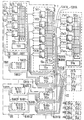
- Exemplary embodiments of the switching system according to the invention will now be explained in more detail with reference to the figure. The details of the system are shown here only to the extent that it is of importance for the invention, which primarily affects the structure of the switching matrix in partial switching matrixes including associated control units and on the establishment of connecting paths between inputs of input partial switching matrixes.
- the input partial switching matrixes 1TG1 ... 1TG32 are shown, which the control units 1S1 ... 1S32 have.
- the setting device 1E1 is also shown, which is supplied by the control unit 1S1 with setting signals.
- the subscriber connections T1 ... T64 whose associated 64 subscriber circuits are combined to form the 1L11 multiple connection circuit, are provided in this partial input switching matrix.
- the 32 connecting lines V1 ... V32 are provided there, through which external traffic is routed to other offices.
- the associated connection circuits are combined to form the 1L12 multiple connection circuit.
- Such subscriber connections and connecting lines are also provided in the 1TG32 input switching matrix. These subscriber lines include the T1985 subscriber line.
- connection paths via which the input switching elements 1TG1 ... 1TF32 can be interconnected are routed via the two auxiliary switching elements 1HKa and 1HKb. These two auxiliary switching elements have the control units 1Sa and 1Sb.
- the setting device 1Ea is also shown for the auxiliary switching matrix 1HKa.
- the connection paths between the input sub-switch 1TG1 and the auxiliary sub-switch 1HKa are via the 32 intermediate lines 1HA1. With the 1TG1 input sub-switch, they are connected via the 1L13 multiple connection circuit and with the 1HKa auxiliary switch, via the 1H32 multiple-connection circuit.
- the connection paths between the input switching matrix 1TG1 and the auxiliary switching matrix 1KHb lead via the 32 intermediate lines 1HB1.
- the auxiliary switching elements 1HKa and 1HKb are connected in a corresponding manner to the other input switching elements via intermediate lines. They are connected to the 1TG32 input sub-switch via the 1HA32 and 1 HB32 intermediate cables.
- the sub-switching networks 1TG1 ... 1TG32 as well as 1HKa and 1HKb described above together with the associated individual control units form sub-switching group I.
- connection path is to be established between two subscriber connections of one and the same input sub-switching matrix, then only the associated control unit including the setting device is to be used for this. If, for example, a connection path is to be established between the subscriber line T1 and the subscriber line T64 of the incoming sub-switching matrix 1TG1, the control unit 1S1 converts, for example, the phone number supplied via the subscriber line T1 and the data bus 101 into the connection position of the subscriber line T64 designated by the number, which is done with cooperation the setting device 1E1 the connection path between the subscriber connections T1 and T64 is interconnected via the input switching matrix 1TG1.
- a connection path between subscriber connections of different input sub-switching networks is interconnected via a single auxiliary switching network, for example via the auxiliary switching network 1HKa. If, for example, a telephone number is supplied via the subscriber line T1, which requests a connection path to the subscriber line T1985 at the incoming sub-switching matrix 1TG32, the result of a conversion attempt using the control unit 1S1 is that the connection location of this desired subscriber line T1985 cannot be determined, since the conversion of the in In this case the run number chosen cannot be carried out there.
- control unit 1S1 of the part acting here as the original input part switching matrix In the switching matrix 1TG1 a connecting path section to the auxiliary switching matrix 1HKa is then occupied, which leads via one of the intermediate lines 1HA1.
- the dialed call number is then sent via this connection path section via the multiple connection circuit 1H1 and the data bus 1Da to the control unit 1Sa, which in turn forwards this call number to the other input switching network via the auxiliary switching network 1HKa.
- the control unit 1S32 of the input part coupling oath 1TG32 which is the destination input part switching field here, will report the convertibility of the dialed number to the control unit 1Sa, via one of the intermediate lines 1HA32.
- the control unit 1Sa then occupies the connecting path section which continues via this intermediate line, with which the connecting path has already been continued from the original input partial switching matrix 1TG1 via the auxiliary partial switching matrix 1HKa to the target input partial switching matrix 1TG32.
- the two intermediate lines already occupied according to the above description have been interconnected with the aid of the control unit 1Sa and the setting device 1Ea within the auxiliary switching unit 1HKa.
- the control unit 1S32 then connects the connection path after converting the dialed number into the connection position of the subscriber line T1985 designated by it via its input switching matrix 1TG32 to this requested subscriber line T1985. Obviously, the connection paths in this way can be established between all subscriber connections of the input sub-switching matrixes 1TG1 ...
- connection paths can be switched between two sub-switching networks here.
- Hilisteit coupling fields 1HKa and 1HKb can also be represented. Alleyways can therefore be largely avoided, especially if the sub-switching networks are designed as complete bundles, for example.
- the two examples of connection paths described confirm that the shortest possible connection path between the subscriber connections to be connected is found automatically.
- the switching matrix shown in the figure now has not only the partial switching matrix group I but also other such switching matrix groups, the last of which is the partial switching matrix group XVI.
- the input switching matrix group XVI includes the input switching elements 16TG1 ... 16TG32 with the associated control units 16S1 ... 16S32 as well as the auxiliary switching elements 16HKa and 16HKb with the control units 16Sa and 16Sb.
- the sub-switching network group XVI belonging to the switching network group XVI are connected via the intermediate lines 16HA1 ... 16HA32 and 16HB1 ... 16HB32.
- XVI are in turn connected via the additional sub-switching matrixes ZK1a, ZK1b, ZK1c, in accordance with how the input sub-switching matrixes are each connected via auxiliary sub-switching matrixes, namely in each case via intermediate lines.
- These include the intermediate lines 1ZA1A, 1ZB1A, 16ZA1A, 16ZB1A and 1ZA1B, 1ZB1B and 16ZB1B.
- the auxiliary switching network 1HKa connected to the additional switching network ZK1a via the 64 intermediate lines 1ZA1A.
- the additional multiple switching circuit ZK1a also contains the further multiple connection circuits Z1a2, Z1a3, Z1a4, to which the already mentioned intermediate lines 1ZB1A, 16ZA1A and 16ZB1A lead.
- the intermediate lines 1ZA1b, 1ZB1B and 16ZB1B are connected to the additional part switching networks ZK1b, ZK1c and ZK1d.
- the connection path is then routed via one of the additional switching elements ZK1a ... ZK1d. This is solved in each case by the fact that no incoming sub-switching network of the sub-switching group with the original incoming sub-switching network reports that the dialed number can be converted.
- the control unit 1S1 of the originating input switching matrix 1TG1 determines that the dialed number cannot be converted. Thereupon, a connection path section to an auxiliary switching matrix, for example to the auxiliary switching matrix 1HKa, is occupied in the manner already described. The associated control unit 1Sa then determines that none of the other control units of the input switching matrix of sub switching matrix group I reports the convertibility of the dialed number.
- connection path sections are temporarily occupied, which belong to intermediate lines which lead to these input sub-switching networks.
- the control unit 1Sa then forwards the dialed number to a control unit of an additional switching matrix, for example to the control unit S1a of the additional switching matrix ZK1a, via one of the intermediate lines 1ZA1A.
- This control unit S1a then also forwards this call number, for example via one of the intermediate lines 16ZBA to the sub-switching network 16HKb with the control unit 16Sb.
- the connection path is then forwarded from there using the dialed number to the destination input switching matrix 16TG1 via one of the intermediate lines 16HA32, which has the subscriber connection T30721.
- control unit 16S1 has reported that the dialed number can be converted and then switches the connection path to after conversion required subscriber connection T30721 through its input sub-switching matrix 16TG1.
- the connection path is connected through the associated control unit 16Sb in a corresponding manner via the additional parts switching network 16HKb, and is also switched through with the aid of the control unit S1a and the setting device E1a at the additional parts switching network ZK1a.
- the control units 1S1 and 1Sa have previously switched the connection path at the original input switching matrix 1TG1 and at the auxiliary switching matrix 1HKa.
- connection path from the subscriber line T1 thus leads via the multiple connection circuit 1L11, the original input partial switching matrix 1TG1, one of the intermediate lines 1HA1 to the multiple connection circuit 1H1 and to the auxiliary partial switching matrix 1HKa. From there it continues via the multiple connection circuit 1H33 and one of the intermediate lines 1ZA1A to the multiple connection circuit Z1a1 to the additional switching matrix ZK1a. From there it is routed via the multiple connection circuit Z1a4, one of the intermediate lines 16ZB1A, the auxiliary switching matrix 16HKb, one of the intermediate lines 16HA32 and the target input partial switching matrix 16TG1 to the target subscriber connection T30721.
- the additional sub-switching network ZK1a with the help of the associated control unit S1a is usually used to determine the destination incoming sub-switching network with several and possibly even all sub-switching groups except for the sub-switching group with the original incoming sub-switching network using the dialed number
- the ability to convert this number reports so that the connection path can be established there in the manner already described.
- connection path sections leading via different intermediate lines are to be temporarily occupied.
- these temporary assignments only take a short amount of time compared to assignments for voice connections. The production of connection paths for such speech connections is therefore only slightly affected by this. In contrast, the burden on control devices is comparatively greater.
- a blocking of the connection establishment can also be avoided by changing the forwarding of dialed numbers from the respective sub-switching network under the connection sections continuing in the direction of the destination incoming sub-switching network in order to reach another auxiliary switching network or additional switching network if the control unit working at the previously reached switching network changes reports as overloaded by mediation processes. This prevents the transfer of phone numbers by an overloaded control unit.
- This defense can also be used as a precautionary measure before an overload occurs, in order to keep the control unit free for the processing of other switching processes, for example for the separation of switching processes, for example for the separation of connection paths.
- control units may have to be used for the establishment of connection paths, this can prevent other switching processes from being blocked in an impermissible manner. If necessary, further measures can be provided for this, for example a temporary restriction of those operating options that require more than the minimum number of control processes for the establishment or separation of connection paths or the control processes for further orders for subscriber connections (see, for example, DE- PS 1 940 502).
- connection paths can be established using uniform control technology that connect the subscriber connections of one and the same input sub-switching network, subscriber connections of different input sub-switching networks of one and the same sub-switching network group and subscriber connections of input sub-switching networks of different sub-switching network groups.
- the shortest connection path between such subscriber connections is also established automatically.
- the control units advantageously carry out processes that correspond to one another. They can therefore also be constructed largely in accordance with each other. Changes in the connection positions only result in changes in the control units, which belong to the affected sub-switching areas. The other control units remain unaffected.
- the switching system according to the invention therefore has a structure which enables it to be constructed in a modular manner from sub-devices which are largely identical to one another. This also applies to extensions to the switching system.
- additional additional switching elements such as the additional switching elements ZK4a, ZK4b, ZK4c and ZK4d together with the associated control units S4 and S4a4.
- additional additional switching elements are connected to the additional switching elements of the switching matrix groups I..XVI via the intermediate services ZZ, which are, however, only indicated schematically in the figure.
- ZK4d and the corresponding further additional sub-switching networks are in turn connected to their own sub-switching groups, not shown in the figure.
- the intermediate lines ZZ it is then also possible to establish connection paths between subscriber connections of all of these sub-switching groups pen are manufactured.
- the intermediate line between the additional sub-switching arrays of different sub-switching array groups can also be routed in a mesh shape. In the figure it is indicated that they are connected to the additional switching elements in the same way as the other intermediate lines, which lead to the auxiliary switching elements.
- ZKla additional parts switching network intermediate lines leading to other additional parts switching networks are connected via the multiple connection Z1az.
- the switching matrix shown in the figure can be extended analogously by additional switching matrixes, without changes in the mode of operation of the control units belonging to the partial switching matrixes being necessary.
- the intermediate lines ZZ are expediently also arranged in such a way that a plurality of connection paths can be switched through between each of the additional coupling elements.
- the subscriber connections T1 ... T64 ... T1985 ... T30721 in the exemplary embodiment shown in the figure are connected to the switching matrix according to the reverse grouping (see NTZ, 1969, number 10, pages 588-596).
- the connection paths therefore reverse within or at the edge of the switching matrix, starting from a subscriber line and returning to another telephony line.
- the connection sets and further shading elements required for each connection are expediently connected in the same way as the subscriber connections to the inputs of input switching elements (see DE-PS 1 235 297). This results in an extensive standardization of the switching processes in the sub-switch coupling fields.
- connection paths can e.g. are separated in each case with the aid of a control signal supplied by the control unit of an input sub-switching network, which is received by the control units of the other sub-switching networks involved in the connection path and is used there for the separation in the associated sub-switching network.
- connecting lines for external traffic are also connected to the inputs of the input switching matrix, as for the 1TG1 input switching matrix, the connecting cables V1 ... V32 via the multiple connection 1L12.
- At least one connecting line for each external direction is expediently connected to each input partial switching matrix.
- connection requests for external traffic can already be forwarded alone via the input sub-switching matrix when the subscriber line requesting this connection path is connected when a connecting line leading in the relevant external direction is free.
- the connection location of a connecting line in question results from the conversion of the phone number supplied by the requesting subscriber line.
- the dialed number can be forwarded to an auxiliary switching network, which in turn then forwards this number to the other incoming switching network until a free connection line is reported in the course of the revaluation of this number carried out by the associated control units which continues in the requested external direction.
- the brokerage for external traffic is therefore handled in the same way as the brokerage for internal traffic. If necessary, it can also be routed via additional parts coupling fields. This results in a very good utilization of the connecting lines leading in external directions. If changes are made to the connection of such connecting lines to an input sub-switching network, this only affects the conversion for this input sub-switching network itself. There is therefore no need to intervene in the control units of other input switching elements or other other switching elements in this connection.
- a detection system which is constructed in accordance with the technology according to the invention can also be connected to superordinate digital independent computing systems by means of which operations for the operation and maintenance and other operations can be carried out (see DE-PS 2 139 275). Such a computing system can also be used to monitor the operability of the various control units and control the equivalent circuit.
Landscapes
- Engineering & Computer Science (AREA)
- Computer Networks & Wireless Communication (AREA)
- Exchange Systems With Centralized Control (AREA)
- Mobile Radio Communication Systems (AREA)
Claims (15)
Priority Applications (1)
| Application Number | Priority Date | Filing Date | Title |
|---|---|---|---|
| AT80101220T ATE3741T1 (de) | 1979-03-15 | 1980-03-10 | Indirekt gesteuerte vermittlungsanlage, insbesondere fernsprechvermittlungsanlage. |
Applications Claiming Priority (2)
| Application Number | Priority Date | Filing Date | Title |
|---|---|---|---|
| DE2910253A DE2910253C2 (de) | 1979-03-15 | 1979-03-15 | Indirekt gesteuerte Vermittlungsanlage, insbesondere Fernsprechvermittlungsanlage |
| DE2910253 | 1979-03-15 |
Publications (2)
| Publication Number | Publication Date |
|---|---|
| EP0016397A1 EP0016397A1 (fr) | 1980-10-01 |
| EP0016397B1 true EP0016397B1 (fr) | 1983-06-08 |
Family
ID=6065517
Family Applications (1)
| Application Number | Title | Priority Date | Filing Date |
|---|---|---|---|
| EP80101220A Expired EP0016397B1 (fr) | 1979-03-15 | 1980-03-10 | Système de commutation à commande indirecte, en particulier système de commutation téléphonique |
Country Status (6)
| Country | Link |
|---|---|
| EP (1) | EP0016397B1 (fr) |
| JP (1) | JPS55124386A (fr) |
| AT (1) | ATE3741T1 (fr) |
| DE (1) | DE2910253C2 (fr) |
| FI (1) | FI800799A7 (fr) |
| ZA (1) | ZA801517B (fr) |
Families Citing this family (2)
| Publication number | Priority date | Publication date | Assignee | Title |
|---|---|---|---|---|
| DE3404087A1 (de) * | 1984-02-06 | 1985-09-26 | Siemens AG, 1000 Berlin und 8000 München | Indirekt gesteuerte vermittlungsanlage mit einem koppelfeld mit mehreren individuell gesteuerten teilkoppelfeldern |
| US5276445A (en) * | 1990-11-30 | 1994-01-04 | Sony Corporation | Polling control system for switching units in a plural stage switching matrix |
Family Cites Families (9)
| Publication number | Priority date | Publication date | Assignee | Title |
|---|---|---|---|---|
| DE1094309B (de) * | 1959-05-14 | 1960-12-08 | Siemens Ag | Fernsprech-Vermittlungssystem mit Koordinatenschaltern als Verbindungsorganen, welche durch Markierer eingestellt werden |
| NL253844A (fr) * | 1959-07-18 | |||
| DE1235379B (de) * | 1964-04-03 | 1967-03-02 | Siemens Ag | Anordnung fuer Fernmeldevermittlungsanlagen, insbesondere Fernsprechvermittlungsanlagen |
| US3376393A (en) * | 1964-09-22 | 1968-04-02 | North Electric Co | Method of and apparatus for providing different release signals with detection of search busy or cut-through busy condition in a saturation signalling system |
| BE787244A (fr) * | 1971-08-05 | 1973-02-05 | Siemens Ag | Systeme pour le deroulement d'operations d'exploitation pour centraux de telecommunications a commande par calculateurs, notammentpour centraux telephoniques |
| CH547590A (de) * | 1973-03-21 | 1974-03-29 | Ibm | Fernmelde-vermittlungsanlage. |
| US3974343A (en) * | 1975-01-10 | 1976-08-10 | North Electric Company | Small modular communications switching system with distributed programmable control |
| DE2553407C3 (de) * | 1975-11-27 | 1979-09-20 | Siemens Ag, 1000 Berlin Und 8000 Muenchen | Schaltungsanordnung für Fernmeldevermittlungsanlagen, insbesondere Fernsprechvermittlungsanlagen, mit Koppelfeldern mit Umkehrgruppierung |
| FR2366754A1 (fr) * | 1976-10-04 | 1978-04-28 | Ibm France | Reseau de commutation modulaire |
-
1979
- 1979-03-15 DE DE2910253A patent/DE2910253C2/de not_active Expired
-
1980
- 1980-03-10 EP EP80101220A patent/EP0016397B1/fr not_active Expired
- 1980-03-10 AT AT80101220T patent/ATE3741T1/de not_active IP Right Cessation
- 1980-03-13 JP JP3096580A patent/JPS55124386A/ja active Pending
- 1980-03-14 FI FI800799A patent/FI800799A7/fi not_active Application Discontinuation
- 1980-03-14 ZA ZA00801517A patent/ZA801517B/xx unknown
Also Published As
| Publication number | Publication date |
|---|---|
| JPS55124386A (en) | 1980-09-25 |
| EP0016397A1 (fr) | 1980-10-01 |
| ATE3741T1 (de) | 1983-06-15 |
| ZA801517B (en) | 1981-03-25 |
| DE2910253C2 (de) | 1983-08-18 |
| DE2910253A1 (de) | 1980-09-25 |
| FI800799A7 (fi) | 1981-01-01 |
Similar Documents
| Publication | Publication Date | Title |
|---|---|---|
| DE3587028T2 (de) | Neueinrichtungsfaehiges mehrstufiges schaltnetzwerk mit vollstaendiger verfuegbarkeit und mit redudantem leiter. | |
| EP0006132B1 (fr) | Système de commutation à commande indirecte avec joncteurs à division temporelle couplés à travers des étages de commutation temporelle, en particulier système de commutation téléphonique | |
| DE4415016A1 (de) | Verfahren zum Betreiben eines Koppelnetzes sowie Koppelnetz und Vermittlungsstelle dafür | |
| WO1999011031A1 (fr) | Dispositif de transmission pour la transmission de signaux de communication | |
| EP0338640B1 (fr) | Réseau de télécommunication à mailles | |
| EP0016397B1 (fr) | Système de commutation à commande indirecte, en particulier système de commutation téléphonique | |
| EP0016396B1 (fr) | Réseau de connexion à groupage à rebroussement, spécialement pour systèmes de commutation téléphonique | |
| DE3224459A1 (de) | Schaltungsanordnung fuer fernmeldevermittlungsanlagen, insbesondere fernsprechvermittlungsanlagen, mit konzentratoren mit insel-vermittlungsbetrieb bei funktionsausfall der konzentratorsteuerleitungen | |
| DE3233221A1 (de) | Schaltungsanordnung zum uebertragen von signalen zwischen teilnehmeranschlussleitungen und wenigstens einer uebertragungsleitung einer dienstintegrierten fernmeldeanlage | |
| DE4423792A1 (de) | Verfahren und Schaltungsanordnung zur Mehrfachausnutzung von Basiskanälen im ISDN | |
| DE3626870C2 (fr) | ||
| DE3023205A1 (de) | Verbindungseinrichtung fuer ein zeitmultiplex-telefonvermittlungssystem | |
| EP0333126B1 (fr) | Central de télécommunication privé pour transmission de signaux à large bande | |
| DE3609889C2 (fr) | ||
| EP0211245B1 (fr) | Montage pour des centraux de télécommunications, en particulier des centraux téléphoniques, comprenant des réseaux de commutation pour connexions à canal unique ou à canaux multiples | |
| DE3404087C2 (fr) | ||
| DE2360391C3 (de) | Fernmeldevermittlungsnetz mit zentralisierter, speicherorientierter Prozessorsteuerung | |
| EP0140142B1 (fr) | Réseau de connexion à groupage à rebroussement, en particulier pour systèmes de commutation téléphonique | |
| DE2553407C3 (de) | Schaltungsanordnung für Fernmeldevermittlungsanlagen, insbesondere Fernsprechvermittlungsanlagen, mit Koppelfeldern mit Umkehrgruppierung | |
| DE3343280A1 (de) | Nachrichtenvermittlungssystem | |
| DE4314791A1 (de) | Vermittlungssystem | |
| DE69635432T2 (de) | Netzwerkarchitektur | |
| DE1762881C3 (de) | Schaltungsanordnung für Fernmeldevermittlungsanlagen, mit Notbetriebsmöglichkeiten | |
| DE2224067C2 (de) | Schaltungsanordnung für Fernmeldevermittlungsanlagen, insbesondere Fernsprechvermittlungsanlagen, mit der Verbindungsherstellung dienenden Datenübertragungseinrichtung | |
| DE2542814C2 (de) | Fernmelde-, insbesondere Fernsprechnebenstellenanlage, mit einem an Leitungsübertragungen angeschlossenen Koppelpunktvielfach und einem Koppelnetzwerk für Durchgangsverbindungen |
Legal Events
| Date | Code | Title | Description |
|---|---|---|---|
| PUAI | Public reference made under article 153(3) epc to a published international application that has entered the european phase |
Free format text: ORIGINAL CODE: 0009012 |
|
| AK | Designated contracting states |
Designated state(s): AT CH FR GB IT NL SE |
|
| 17P | Request for examination filed |
Effective date: 19810331 |
|
| ITF | It: translation for a ep patent filed | ||
| GRAA | (expected) grant |
Free format text: ORIGINAL CODE: 0009210 |
|
| AK | Designated contracting states |
Designated state(s): AT CH FR GB IT NL SE |
|
| PG25 | Lapsed in a contracting state [announced via postgrant information from national office to epo] |
Ref country code: SE Effective date: 19830608 Ref country code: NL Effective date: 19830608 Ref country code: FR Free format text: THE PATENT HAS BEEN ANNULLED BY A DECISION OF A NATIONAL AUTHORITY Effective date: 19830608 |
|
| REF | Corresponds to: |
Ref document number: 3741 Country of ref document: AT Date of ref document: 19830615 Kind code of ref document: T |
|
| NLV1 | Nl: lapsed or annulled due to failure to fulfill the requirements of art. 29p and 29m of the patents act | ||
| PG25 | Lapsed in a contracting state [announced via postgrant information from national office to epo] |
Ref country code: AT Effective date: 19840310 |
|
| EN | Fr: translation not filed | ||
| PG25 | Lapsed in a contracting state [announced via postgrant information from national office to epo] |
Ref country code: CH Effective date: 19840331 |
|
| PLBE | No opposition filed within time limit |
Free format text: ORIGINAL CODE: 0009261 |
|
| STAA | Information on the status of an ep patent application or granted ep patent |
Free format text: STATUS: NO OPPOSITION FILED WITHIN TIME LIMIT |
|
| 26N | No opposition filed | ||
| GBPC | Gb: european patent ceased through non-payment of renewal fee | ||
| GBPC | Gb: european patent ceased through non-payment of renewal fee | ||
| REG | Reference to a national code |
Ref country code: CH Ref legal event code: PL |
|
| PG25 | Lapsed in a contracting state [announced via postgrant information from national office to epo] |
Ref country code: GB Effective date: 19881118 |